EP0862153A2 - Tiroir-caisse - Google Patents
Tiroir-caisse Download PDFInfo
- Publication number
- EP0862153A2 EP0862153A2 EP98300862A EP98300862A EP0862153A2 EP 0862153 A2 EP0862153 A2 EP 0862153A2 EP 98300862 A EP98300862 A EP 98300862A EP 98300862 A EP98300862 A EP 98300862A EP 0862153 A2 EP0862153 A2 EP 0862153A2
- Authority
- EP
- European Patent Office
- Prior art keywords
- divider
- drawer box
- bottomed
- note
- accommodation part
- Prior art date
- Legal status (The legal status is an assumption and is not a legal conclusion. Google has not performed a legal analysis and makes no representation as to the accuracy of the status listed.)
- Granted
Links
Images











Classifications
-
- G—PHYSICS
- G07—CHECKING-DEVICES
- G07G—REGISTERING THE RECEIPT OF CASH, VALUABLES, OR TOKENS
- G07G1/00—Cash registers
- G07G1/0018—Constructional details, e.g. of drawer, printing means, input means
- G07G1/0027—Details of drawer or money-box
-
- A—HUMAN NECESSITIES
- A47—FURNITURE; DOMESTIC ARTICLES OR APPLIANCES; COFFEE MILLS; SPICE MILLS; SUCTION CLEANERS IN GENERAL
- A47B—TABLES; DESKS; OFFICE FURNITURE; CABINETS; DRAWERS; GENERAL DETAILS OF FURNITURE
- A47B88/00—Drawers for tables, cabinets or like furniture; Guides for drawers
- A47B88/90—Constructional details of drawers
-
- A—HUMAN NECESSITIES
- A47—FURNITURE; DOMESTIC ARTICLES OR APPLIANCES; COFFEE MILLS; SPICE MILLS; SUCTION CLEANERS IN GENERAL
- A47B—TABLES; DESKS; OFFICE FURNITURE; CABINETS; DRAWERS; GENERAL DETAILS OF FURNITURE
- A47B88/00—Drawers for tables, cabinets or like furniture; Guides for drawers
- A47B88/90—Constructional details of drawers
- A47B88/969—Drawers having means for organising or sorting the content
- A47B88/994—Drawers having means for organising or sorting the content in the form of trays or inserts
Definitions
- the present invention relates to a drawer box which is included in an electronic money register, a POS terminal, and the like for accommodating coins and notes, and papers such as checks and gift tokens.
- a drawer box for accommodating money in an electronic money register, a POS terminal, and the like is usually structured to include a resin-molded money case provided in a main body of the drawer-type box.
- Figure 20 illustrates an exemplary conventional money case.
- the money case includes a plurality of coin accommodation portions 1 in a front part thereof, and a plurality of note accommodation portions 2 for horizontally accommodating notes in a stacked manner which are posterior to the coin accommodation portions 1 .
- the note accommodation portions 2 are arranged side by side along a width direction (arrow W) of the money case.
- the coin accommodation portions 1 have a deep-bottomed shape having a depth substantially equal to the height of the money case, while the note accommodation portions 2 have a shallow-bottomed shape having a depth substantially half of the height of the money case.
- the note accommodation portions 2 have a shallow-bottomed shape, for example, for the following reasons: an increased depth makes it difficult to take out notes; and a lock unit needs to be provided below the note accommodation portions 2 in order to hold the drawer box in an open or closed state.
- a larger note accommodation space is demanded in order to cope with an increase in the numbers of notes caused by issuance of new kinds of high-value notes in overseas countries, and to deal with countries in which many kinds of notes are circulated.
- space-saving is also strongly demanded, which makes it difficult to simply increase the size of the drawer box in order to enlarge the note accommodation space. Therefore, enlargement of the note accommodation space while avoiding an increase in the size of the drawer box has been strongly demanded.
- Drawer boxes proposed to cope with such a demand are disclosed, for example, in Japanese Laid-Open Utility Model Publication No. 6-30883, Japanese Laid-Open Utility Model Publication No. 6-15178, Japanese Laid-Open Publication No. 4-352298, Japanese Laid-Open Publication No. 3-80395, and Japanese Laid-Open Publication No. 2-137089.
- the drawer box disclosed in Japanese Laid-Open Publication No. 4-352298 adopts a structure in which a note accommodation part has a deep-bottomed shape and is divided into an upper and a lower portions by a detachable divider.
- This structure allows the portion above the divider to be used as a note accommodation portion with a shallow bottom in which notes are accommodated horizontally, and also allows the portion below the divider to accommodate notes in the case where there are many kinds of notes. Therefore, the note accommodation space is enlarged while avoiding an increase in the size of the drawer box.
- a drawer box includes: a plurality of note accommodation parts arranged in a width direction of the drawer box, at least one note accommodation part being deep-bottomed with a depth substantially equal to a height of the drawer box; a divider including a bottom plate for dividing the at least one deep-bottomed note accommodation part into an upper portion and a lower portion, the divider further including an upright portion which extends perpendicularly from one end of the bottom plate; a first holding device for holding the divider in a position where the bottom plate divides the at least one deep-bottomed note accommodation part into the upper portion and the lower portion; a guide device for guiding the divider to a bottom position, wherein the divider divides the at least one deep-bottomed note accommodation part into two side portions by the upright portion of the divider; and a second holding device for holding the divider in the bottom position.
- the at least one deep-bottomed note accommodation part including the divider is provided on one side of the drawer box.
- the at least one deep-bottomed note accommodation part including the divider is provided on each of two sides of the drawer box.
- a note accommodation part other than the at least one deep-bottomed note accommodation part has a shallow-bottomed shape
- a lock unit for maintaining the drawer box in an opened or closed state is provided under the note accommodation part having the shallow-bottomed shape.
- the note accommodation part having the shallow-bottomed shape horizontally accommodates notes in a stacked manner.
- a drawer box includes: a plurality of note accommodation parts arranged in a width direction of the drawer box, at least one note accommodation part being deep-bottomed with a depth substantially equal to a height of the drawer box; a divider for dividing the at least one deep-bottomed note accommodation part into an upper portion and a lower portion; a supporting device for supporting the divider within the at least one deep-bottomed note accommodation part, wherein the supporting device is pivotal about an axis existing on the divider; a first holding device for holding the divider in a substantially horizontal position for dividing the at least one deep-bottomed note accommodation part into the upper portion and the lower portion; and a second holding device for holding the divider in a substantially perpendicular position for dividing the at least one deep-bottomed note accommodation part into two side portions.
- the at least one deep-bottomed note accommodation part including the divider is provided on one side of the drawer box.
- the at least one deep-bottomed note accommodation part including the divider is provided on each of two sides of the drawer box.
- a note accommodation part other than the at least one deep-bottomed note accommodation part has a shallow-bottomed shape
- a lock unit for maintaining the drawer box in an opened or closed state is provided under the note accommodation part having the shallow-bottomed shape.
- the note accommodation part having the shallow-bottomed shape horizontally accommodates notes in a stacked manner.
- all of the plurality of note accommodation parts have a deep-bottomed shape and include the divider.
- a drawer box includes: a plurality of note accommodation parts arranged in a width direction of the drawer box, at least one note accommodation part being deep-bottomed with a depth substantially equal to a height of the drawer box; a divider for dividing the at least one deep-bottomed note accommodation part into an upper portion and a lower portion; a first holding device for detachably holding the divider in a position of dividing the at least one deep-bottomed note accommodation part into the upper portion and the lower portion; and a second holding device for detachably holding the divider in a position of dividing the at least one deep-bottomed note accommodation part into two side portions.
- the at least one deep-bottomed note accommodation part including the divider is provided on one side of the drawer box.
- the at least one deep-bottomed note accommodation part including the divider is provided on each of two sides of the drawer box.
- a note accommodation part other than the at least one deep-bottomed note accommodation part has a shallow-bottomed shape
- a lock unit for maintaining the drawer box in an opened or closed state is provided under the note accommodation part having the shallow-bottomed shape.
- the note accommodation part having the shallow-bottomed shape horizontally accommodates notes in a stacked manner.
- all of the plurality of note accommodation parts have a deep-bottomed shape and include the divider.
- a drawer box includes: a plurality of coin accommodation parts provided in the drawer box; a divider detachably provided in the drawer box for dividing at least one of the plurality of coin accommodation parts into at least two coin accommodation portions; a first holding device for detachably holding the divider in a position of dividing the at least one coin accommodation part into at least two coin accommodation portions; and a second holding device for pivotally hinging the divider to a top edge of a wall of the at least one coin accommodation part about a horizontal axis.
- a drawer box further includes a locking device for locking a free end of the divider to a wall portion opposing to the wall portion to which the divider is hinged when the divider is hinged.
- a total size of the two adjacent coin accommodation portions is sufficient to accommodate notes.
- the guide device obliquely guides the divider to a bottom position, wherein the divider divides the at least one deep-bottomed note accommodation part into two side portions by the upright portion of the divider.
- the invention described herein makes possible the advantages of providing (1) a drawer box for enlarging a note accommodation space while avoiding an increase in the size of the drawer box; and (2) a drawer box for facilitating the deposit and retrieval of notes and the recognition of notes in an enlarged note accommodation space.
- FIGs 1 through 5 illustrate a drawer box 100 in Example 1 according to the present invention.
- the drawer box 100 includes a money case 300.
- the money case 300 includes a casing 70 formed by resin-molding, a coin accommodation area 10 which is detachably engageable in a front portion of the casing 70, and a note accommodation area 20 provided posterior to the front portion of the casing 70.
- the coin accommodation area 10 includes a plurality of coin accommodation parts 10a arranged in two rows, each row having two coin accommodation parts 10a in a width direction W of the money case 300.
- Each coin accommodation part 10a has two coin accommodation portions 10b separated from each other by a divider 30.
- the note accommodation area 20 includes a plurality of note accommodation parts 20a and 20b arranged in the width direction W of the money case 300.
- the drawer box 100 of Example 1 adopts a divider rearrangement system (described in detail later) for the coin accommodation area 10, and a divider lifting and lowering system (described in detail later) for the note accommodation area 20.
- the note accommodation area 20 which adopts the divider lifting and lowering system will be described below with reference to Figures 3A, 3B and 3C.
- the note accommodation area 20 includes one note accommodation part 20a of a first type and three note accommodation parts 20b of a second type.
- the note accommodation part 20a located at one end the note accommodation area 20 has a deep-bottomed shape having a depth substantially equal to the height of the money case 300.
- the note accommodation parts 20b have a shallow-bottomed shape having a depth substantially half of the height of the money case 300.
- the height of the money case 300 is substantially the same as that of the drawer box 100.
- the note accommodation part 20a has an upper portion 201a and a lower portion 201b, and the lower portion 201b is larger in the width direction W than the upper portion 201a.
- the note accommodation part 20a is placed between an L-shaped outer wall 21 and a laterally staggered inner wall 22 as illustrated in Figures 3A, 3B and 3C.
- An opening 24 is placed between bottom portions of the walls 21 and 22.
- the note accommodation area 20 further includes a divider 40 having an L-shaped cross section.
- the divider 40 has a bottom plate 41 for separating the upper portion 201a from the lower portion 201b ( Figure 3A ), and an upright portion 42 extended perpendicularly from one end of the bottom plate 41.
- a convex portion 41a is provided along the entire length thereof.
- a projection 41b is provided on each of a front and a back surface of the bottom plate 41 extending in the width direction W (only the one on the back surface is shown).
- the walls 21 and 22 each have a concave portion 23 at an intermediate position thereof in which each convex portion 41a of the divider 40 is engageable.
- Each of the walls 21 and 22 also has a concave portion 25 at a bottom position thereof in which each convex portion 41a of the divider 40 is also engageable.
- grooves 26 extending from an intermediate position to a bottom position in an inwardly inclined manner.
- the projections 41b of the divider 40 are respectively slidable along the grooves 26.
- the divider 40 is normally held so as to allow the bottom plate 41 to be horizontally held in the intermediate level of the note accommodation part 20a.
- the convex portions 41a provided on the side surfaces of the bottom plate 41 fit into the concave portions 23 which are formed in the intermediate positions of the two walls 21 and 22.
- the convex portions 41a and the concave portions 23 function as a first holding device.
- the upright portion 42 of the divider 40 is substantially entirely in contact with the wall 21.
- the upper portion 201a acts as a shallow-bottomed note accommodation part similar to the adjacent note accommodation parts 20b. Notes can be accommodated horizontally in the note accommodation part.
- the divider 40 is swung slightly, disengaging the convex portions 41a of the divider 40 from the concave portions 23 as shown in Figure 3B. This causes the divider 40 to slide obliquely downward by a sliding movement of the projections 41b along the inclined grooves 26. The projections 41b and the grooves 26 function together as a guide device. Then, as shown in Figure 3C, the divider 40 is lowered to the point where the convex portions 41a are fitted into the concave portions 25, thereby locking the bottom plate 41 in the opening 24 at a bottom position. The convex portions 41a and the concave portions 25 function as a second holding device.
- the upright portion 42 When the bottom plate 41 lowers, the upright portion 42 also moves inwardly while lowering. In the state where the bottom plate 41 is locked at the bottom position of the note accommodation part 20a, the upright portion 42 is held securely in a position which divides the note accommodation part 20a into two side portions. In this state, the upper portion 201a and the lower portion 201b act together as a deep-bottomed note accommodation part. Notes can be accommodated vertically.
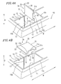
- the coin accommodation area 10 includes the coin accommodation parts 10a divided into two coin accommodation portions 10b by the removable divider 30.
- the divider 30 has projections 31b and a cut-out 31a on a front edge 36, and a pair of projections 32 on both of two ends of a rear edge 34 of the divider 30.
- Each projection 32 has a rounded concave portion 33 in an outer surface thereof.
- the coin accommodation part 10a is placed between walls 11 and 12.
- the walls 11 and 12 each has a groove 13 extending in a depth direction (arrow D).
- the projections 31b and the projections 32 are engageable with the grooves 13.
- the divider 30 is vertically secured in the coin accommodation part 10a through the engagement of the projections 31b and one of the grooves 13, and the projections 32 and the other groove 13, the coin accommodation part 10a is divided into two coin accommodation portions 10b.
- the projections 31b and 32, and the grooves 13 function as a first holding device.
- the wall 12 has concave portions 14 in the top edge thereof, in which the projections 32 of the divider 30 are engageable.
- the wall 12 has projections 15 projecting into the concave portions 14, wherein the projections 15 are engageable in the concave portions 33 which exist within the projections 32 of the divider 30.
- the concave portions 33 and the projections 15 function as a second holding device in a form of a hinge for attaching the divider 30 to the wall 12.
- the divider 30 pivots in a direction of arrow A, as illustrated in Figure 5.
- the wall 11 has a slit 16.
- a free end of the divider 30, i.e., the projections 31b, is engageable in the slit 16.
- the slit 16 and the projections 31b function as a locking device for locking the divider 30 to the wall 11.
- the divider 30 is normally inserted vertically into the grooves 13, thereby acting as a partition between the coin accommodation portions 10b.
- the divider 30 is pulled out of the grooves 13 as shown in Figure 4A.
- the coin accommodation part 10a acts as a note accommodation part, wherein the notes are accommodated horizontally.
- an additional note accommodation space is obtained.
- the divider 30 is turned horizontally ( Figure 4B). Then, the projections 32 of the divider 30 are fit into the concave portions 14, and the projections 15 are fit into the concave portions 33. This causes the divider 30 to be hinged to the top edge of the wall 12 with the rear edge 34 serving as a fulcrum (horizontal axis). Then, the free end of the hinged divider 30 is swung and pressed downward with the projections 31b pressed against a note-weight locking device 16' to the point where the projections 31b are inserted into the slit 16.
- the note-weight locking device 16' is made of resin. Accordingly, when the tips of the projections 31b of the divider 30 touch the note-weight locking device 16', the note-weight locking device 16' elastically deforms in a forward direction (arrow F) in Figure 5. Then, when the projections 31b reach the slit 16, the note-weight locking device 16' recovers the original shape thereof due to elasticity, thus holding the divider 30 as shown by a solid line in Figure 5. In this state, the divider 30 functions as a weight for notes 50 accommodated in the coin accommodation part 10a. This prevents the notes 50 from jumping out of the drawer box 100 when the drawer box 100 is opened and closed even though the note accommodation part is created in the front portion of the money case 300.
- Figures 6A, 6B and 6C illustrate a drawer box 110 including a money case 310 in Example 2 according to the present invention.
- the drawer box 110 adopts the divider lifting and lowering system for the note accommodation area 20 in the money case 310.
- the drawer box 110 is different from the drawer box 100 in that the drawer box 110 has two note accommodation parts 20a located at both of two ends of a row having four note accommodation parts arranged in a width direction W of the money case 310.
- the note accommodation parts 20a include the divider 40 and have a deep-bottomed shape. This further provides an additional note accommodation space.
- the two note accommodation parts 20b placed between the note accommodation parts 20a have a shallow bottomed shape.
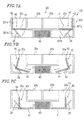
- Figures 7A, 7B, 7C, 8A, 8B and 8C illustrate a drawer box 120 including a money case 320 in Example 3 according to the present invention.
- the drawer box 120 adopts the divider lifting and lowering system for the note accommodation area 20 in the money case 320.
- two note accommodation parts 20a of a deep-bottomed shape including the divider 40 are provided at both of two ends of the row.
- the drawer box 120 is different from the drawer box 110 in Example 2 in that a lock unit 60 for maintaining the drawer box 120 in an opened or closed state is provided under the two note accommodation parts 20b which have a shallow-bottomed shape and are sandwiched between the note accommodation parts 20a.
- lock unit 60 Since the lock unit 60 is commonly used, a detailed description thereof is omitted.
- the lock unit 60 is normally provided at the rear end of the drawer box 120, under the note accommodation parts 20b.
- This structure is made possible by providing the note accommodation parts 20a at the two ends of the row and leaving the note accommodation parts 20b shallow-bottomed.
- FIG 8C by changing the manner of accommodating notes in the note accommodation parts 20a from horizontally to vertically, portions 20a' located on two sides of the lock unit 60 can be used as note accommodation space, thereby increasing the whole note accommodation space.
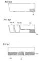
- Figures 9A and 9B illustrate a drawer box 130 including a money case 330 in Example 4 according to the present invention.
- the drawer box 130 adopts a divider pivoting system for the note accommodation area 20 in the money case 330.
- the note accommodation area 20 includes one note accommodation part 20a having an upper portion 201a and a lower portion 201b and a plurality of note accommodation parts 20b. Both note accommodation parts 20a and 20b are arranged in a width direction W of the money case 330.
- the divider 40 is provided to separate the upper portion 201a from the lower portion 201b ( Figure 9A).
- the note accommodation part 20a is partially surrounded by an outer wall 91, an inner wall 92 and a bottom plate 93.
- the divider 40 includes a projection 43 in the middle of each of a front and a back surface thereof.
- the front and back walls of the note accommodation part 20a each have a concave portion (not shown) in which the projection 43 is engageable.
- the projections 43 function as a supporting device for pivotally supporting the divider 40 in an intermediate portion between the front and back walls of the note accommodation part 20a.
- the projections 43 may be positioned at other positions as long as the divider 40 can be held in a horizontal and a vertical position.
- One side surface of the divider 40 extending perpendicular to the width direction W has a convex portion 44 provided along the entire length thereof.
- the inner wall 92 has a concave portion 27a in which the convex portion 44 is engageable so as to hold the divider 40 substantially horizontally.
- the outer wall 91 may have the concave portion 27a.
- the convex portion 44 and the concave portion 27a function as a first holding device.
- the top surface of the bottom plate 93 has a concave portion 27b in which the convex portion 44 is engageable so as to hold the divider 40 in a substantially vertical position which divides the note accommodation part 20a into two side portions.
- the convex portion 44 and the concave portion 27b function as a second holding device.
- the divider 40 is held horizontally in an intermediate level by fitting the convex portion 44 in the concave portion 27a as shown in Figure 9A.
- the upper portion 201a acts as a note accommodation part of a shallow-bottomed shape similar to the note accommodation parts 20b. In this manner notes can be accommodated horizontally.
- the divider 40 is pivoted, thereby disengaging the convex portion 44 from the concave portion 27a and fitting the convex portion 44 into the concave portion 27b as shown in Figure 9B.
- notes can be accommodated vertically in the note accommodation space, the notes can be deposited and retrieved and recognized more easily.
- Figures 10A and 10B illustrate a drawer box 140 including a money case 340 in Example 5 according to the present invention.
- the drawer box 140 adopts the divider pivoting system for the note accommodation area 20 in the money case 340.
- the drawer box 140 is different from the drawer box 130 in that the drawer box 140 has two note accommodation parts 20a located at both of two ends of a row having the four note accommodation parts arranged in a width direction W of the money case 340.
- the note accommodation parts 20a include the divider 40 and have a deep-bottomed shape. This further provides an additional accommodation space.
- the two note accommodation parts 20b placed between the note accommodation parts 20a have a shallow bottomed shape.
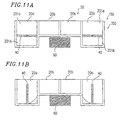
- FIGS 11A and 11B illustrate a drawer box 150 including a money case 350 in Example 6 according to the present invention.
- the drawer box 150 adopts the divider pivoting system for the note accommodation area 20 in the money case 350.
- two note accommodation parts 20a of a deep-bottomed shape including the divider 40 are provided at both of two ends of the row.
- the drawer box 150 is different from the drawer box 140 in Example 5 in that a lock unit 60 for maintaining the drawer box 150 in an opened or closed state is provided under the two note accommodation parts 20b which have a shallow-bottomed shape and are sandwiched between the note accommodation parts 20a.
- the note accommodation space can be increased without sacrificing installment space for the lock unit 60.
- Figures 12A, 12B, 13A, 13B and 13C illustrate a drawer box 160 including a money case 360 in Example 7 according to the present invention.
- the drawer box 160 adopts the divider pivoting system for the note accommodation area 20 in the money case 360.
- the note accommodation area 20 of Example 7 is different from those of Examples 4, 5 and 6 in that the two note accommodation parts 20a are located at one end of the row and include the divider 40 and have a deep-bottomed shape.
- the lock unit 60 is provided under the two note accommodation parts 20b of a shallow-bottomed shape.
- the lock unit 60 can be provided under the note accommodation parts 20b of a shallow-bottomed shape as in a conventional manner.
- portions 20a' located on one side of the lock unit 60 can be used as note accommodation space ( Figure 13C ), thereby increasing the whole note accommodation space.
- the note accommodation space can therefore be increased without sacrificing installment space for the lock unit 60 as in Example 6.
- Figures 14A and 14B illustrate a drawer box 170 including a money case 370 in Example 8 according to the present invention.
- the drawer box 170 adopts the divider pivoting system for the note accommodation area 20 in the money case 370 .
- the note accommodation area 20 of Example 8 is different from those of Examples 4, 5, 6 and 7 in that all the note accommodation parts 20a are arranged in a width direction W of the money case 370 and have a deep-bottomed shape with the divider 40 . This remarkably increases the note accommodation space.
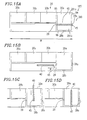
- Figures 15A , 15B , 15C and 15D illustrate a drawer box 180 including a money case 380 in Example 9 according to the present invention.
- the drawer box 180 adopts the divider rearrangement system for the note accommodation area 20 in the money case 380.
- the note accommodation area 20 includes one note accommodation part 20a having an upper portion 201a and a lower portion 201b and a plurality of note accommodation parts 20b, wherein both are arranged in a width direction W of the money case 380.
- the divider 40 separates the upper portion 201a from the lower portion 201b in the note accommodation part 20a ( Figure 15A ).
- the note accommodation part 20a is partially surrounded by an outer wall 94, an inner wall 95 and a bottom plate 96.
- the divider 40 includes a snapfit-type protrusion 45 on one end thereof.
- the outer wall 94 has a slit-like engagement portion 28a at an intermediate position thereof in which the protrusion 45 is engageable.
- the inner wall 95 has a slit 29 through which the divider is inserted so as to oppose the engagement portion 28a.
- the protrusion 45 and the engagement portion 28a serve as a first holding device for detachably holding the divider 40 in a position of separating the upper portion 201a from the lower portion 201b of the note accommodation part 20a ( Figure 15A).
- the inner wall 95 may have the engagement portion 28a and the outer wall 94 may have the slit 29.
- the bottom plate 96 has a slit-like engagement portion 28b on the middle portion of the top surface thereof in which the protrusion 45 is engageable.
- the protrusion 45 and the engagement portion 28b function as a second holding device for detachably holding the divider 40 in a position of dividing the note accommodation part 20a into two side portions.
- the divider 40 is held horizontally in an intermediate level by the fitting the protrusion 45 provided on one end of the divider 40 into the engagement portion 28a and inserting the other end thereof into the slit 29 as shown in Figure 15A.
- the upper portion 201a acts as a note accommodation part of a shallow-bottomed shape similar to the note accommodation parts 20b. In this manner notes can be accommodated horizontally.
- the protrusion 45 is disengaged from the engagement portion 28a, and the divider 40 is retracted through the slit 29 in a direction of arrow B as shown in Figure 15B. Then, as shown in Figures 15C and 15D, the divider 40 is vertically inserted into the note accommodation part 20a with the protrusion 45 facing downward, and the protrusion 45 is fitted into the engagement portion 28b. This divides the note accommodation part 20a into two side portions having a deep-bottomed shape. In this manner notes can be accommodated vertically. This increases the note accommodation space without increasing the width of the drawer box 180.
- notes can be accommodated vertically in the note accommodation space, the notes can be deposited and retrieved and recognized more easily.
- Figures 16A, 16B, 16C and 16D illustrate a drawer box 190 including a money case 390 in Example 10 according to the present invention.
- the drawer box 190 adopts the divider rearrangement system for the note accommodation area 20 in the money case 390.
- the drawer box 190 is different from the drawer box 180 in that the drawer box 190 has two note accommodation parts 20a located at both of two ends of a row having the four note accommodation parts arranged in a width direction W of the money case 390.
- the note accommodation parts 20a include the divider 40 and have a deep-bottomed shape. This further provides an additional note accommodation space.
- the two note accommodation parts 20b placed between the note accommodation parts 20a have a shallow bottomed shape.
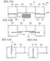
- FIGS 17A, 17B, 17C and 17D illustrate a drawer box 400 including a money case 600 in Example 11 according to the present invention.
- the drawer box 400 adopts the divider rearrangement system for the note accommodation area 20 in the money case 600.
- two note accommodation parts 20a of a deep-bottomed shape including the divider 40 are provided at both of two ends of the row.
- the drawer box 400 is different from the drawer box 190 in Example 10 in that the lock unit 60 for maintaining the drawer box 400 in an opened or closed state is provided under the two note accommodation parts 20b having a shallow-bottomed shape which are sandwiched between the note accommodation parts 20a.
- the note accommodation space can be increased without sacrificing installment space for the lock unit 60.
- the divider 40 can be moved as described above in the state where the money case 600 is taken out of a main body (not shown) of the drawer box 400.
- the lock unit 60 is attached on the bottom surface of the main body. Accordingly, the divider 40 does not interfere with the lock unit 60 while the divider 40 is being moved. This also applies to a drawer box 410 as in Example 12.
- Figures 18A, 18B, 18C and 18D illustrate a drawer box 410 including a money case 610 in Example 12 according to the present invention.
- the drawer box 410 adopts the divider rearrangement system for the note accommodation area 20 in the money case 610.
- the note accommodation area 20 of Example 12 is different from those of Examples 9, 10 and 11 in that two of the note accommodation parts 20a are located at one end of the row and include the divider 40 and have a deep-bottomed shape.
- the lock unit 60 is provided under the two note accommodation parts 20b which have a shallow-bottomed shape. The note accommodation space can be increased without sacrificing installment space for the lock unit 60.
- Figure 19 illustrates a drawer box 420 including a money case 620 in Example 13 according to the present invention.
- the drawer box 420 adopts the divider rearrangement system for the coin accommodation area 10 of a money case.
- the drawer box 420 of Example 13 adopts a locking device for locking a free end 97 of the divider 30 to the wall 11.
- the locking device of Example 13 includes a magnet 35 attached at the free end 97 of the divider 30, and a metal tip 17 attached to the wall 11.
- the magnet 35 contacts the metal tip 17 when the divider 30 is lowered.
- the free end 97 of the divider 30 is locked to the wall 11.
- the divider 30 functions as a weight for notes 50 accommodated horizontally in the note accommodation part. This prevents the notes 50 from jumping out of the drawer box 420 when the drawer box 420 is opened and closed even though the note accommodation part is created in the front portion of the money case 620.
- Figures 3A, 3B, 3C, 6A, 6B, 6C, 7A, 7B and 7C illustrate drawer boxes 100, 110 and 120 including money cases 300, 310 and 320, respectively with a note accommodation area 20 utilizing a divider lifting and lowering system.
- At least one note accommodation part 20a has a deep-bottomed shape having a depth substantially equal to the height of the drawer boxes 100, 110 and 120.
- a divider 40 is provided in the note accommodation part 20a and is held in such a position as to divide the note accommodation part 20a into an upper and a lower portions 201a and 201b, the upper portion 201a functions as a note accommodation part with a shallow bottom, thus enabling the notes to be accommodated horizontally in a stacked manner on the divider 40. Sliding the divider 40 obliquely downward from this position creates a note accommodation part of a deep-bottomed shape above the divider 40, thereby enlarging the note accommodation space without increasing the size of the drawer boxes 100, 110 and 120.
- Figures 9A, 9B, 10A, 10B, 11A, 11B, 11A, 12B, 14A and 14B illustrate drawer boxes 130, 140, 150, 160 and 170 including money cases 330, 340, 350, 360 and 370, respectively with a note accommodation area 20 of a divider pivoting system.
- the divider 40 When the divider 40 is held substantially horizontally so as to divide the note accommodation part 20a into an upper and a lower portions 201a and 201b, notes can be accommodated horizontally in a stacked manner on the divider 40.
- the note accommodation part 20a When the divider 40 is pivoted so as to be substantially vertical, the note accommodation part 20a is divided into two side portions by the divider 40, and the side portions now function as note accommodation parts in which the notes can be accommodated vertically. Pivoting of the divider 40 changes one note accommodation part in which notes are accommodated horizontally, into two note accommodation parts in which notes are accommodated vertically, thereby enlarging the note accommodation space while avoiding an increase in the size of the drawer boxes 130, 140, 150, 160 and 170. Furthermore, depositing and retrieving the notes and recognition of the notes can be easily performed in the enlarged note accommodation space.
- Figures 15A, 15B, 15C, 15D, 16A, 16B, 16C, 16D , 17A, 17B, 17C, 17D, 18A, 18B, 18C and 18D illustrate drawer boxes 180, 190, 400 and 410 including money cases 380, 390, 600 and 610, respectively with a note accommodation area 20 which utilizes a divider rearrangement system.
- Figures 7A, 7B, 7C, 11A, 11B, 12A, 12B, 17A, 17B, 17C, 17D, 18A, 18B, 18C, and 18D illustrate drawer boxes 120, 150, 160, 400 and 410 including money cases 320, 350, 360, 600 and 610 , respectively, in which the note accommodation parts 20a which have a deep-bottomed shape with the divider 40 are provided at one end or at both ends of the drawer boxes 120, 150, 160, 400 and 410.
- the note accommodation parts 20b have a shallow-bottomed shape.
- a lock unit 60 for maintaining the drawer boxes 120, 150, 160, 400 and 410 in an opened or closed state can be provided under the note accommodation parts 20b. Therefore, the note accommodation space can be increased without sacrificing installment space for the lock unit 60.
- Figures 4A, 4B, 5 and 19 illustrate drawer boxes 100 and 420 including money cases 300 and 620, respectively, with a coin accommodation area 10 utilizing a divider rearrangement system.
- a removable divider 30 can be vertically inserted into the coin accommodation part 10a and thereby act as a partition between the two coin accommodation parts 10b.
- the divider 30 is pulled out (when the divider 30 is removed) the notes can be horizontally accommodated in the coin accommodation part 10a. This enlarges a note accommodation space while avoiding an increase in the size of the drawer box. Furthermore, depositing and retrieving the notes and recognition of the notes can be easily performed in the enlarged note accommodation space.
- the divider 30 can be hinged to a top edge of the wall 12, and a free end of the divider 30 is locked to the wall 11. In this state, the divider 30 functions as a weight for notes accommodated in the newly created note accommodation part. This prevents the notes from jumping out of the drawer boxes 100 and 420 when the drawer boxes 100 and 420 are opened and closed even though the note accommodation part is created in the front portion thereof.
- the coin accommodation area 10 of the divider rearrangement system can be combined with the aforementioned note accommodation area 20 of the divider lifting and lowering system, the divider pivoting system, or the divider rearrangement system.
Landscapes
- Physics & Mathematics (AREA)
- General Physics & Mathematics (AREA)
- Cash Registers Or Receiving Machines (AREA)
- Drawers Of Furniture (AREA)
Applications Claiming Priority (3)
| Application Number | Priority Date | Filing Date | Title |
|---|---|---|---|
| JP02942397A JP3312722B2 (ja) | 1997-02-13 | 1997-02-13 | ドロアボックス |
| JP2942397 | 1997-02-13 | ||
| JP29423/97 | 1997-02-13 |
Publications (3)
| Publication Number | Publication Date |
|---|---|
| EP0862153A2 true EP0862153A2 (fr) | 1998-09-02 |
| EP0862153A3 EP0862153A3 (fr) | 1999-05-26 |
| EP0862153B1 EP0862153B1 (fr) | 2003-09-03 |
Family
ID=12275730
Family Applications (1)
| Application Number | Title | Priority Date | Filing Date |
|---|---|---|---|
| EP98300862A Expired - Lifetime EP0862153B1 (fr) | 1997-02-13 | 1998-02-05 | Tiroir-caisse |
Country Status (4)
| Country | Link |
|---|---|
| US (1) | US5992959A (fr) |
| EP (1) | EP0862153B1 (fr) |
| JP (1) | JP3312722B2 (fr) |
| DE (1) | DE69817640T2 (fr) |
Cited By (1)
| Publication number | Priority date | Publication date | Assignee | Title |
|---|---|---|---|---|
| WO2002014762A1 (fr) * | 2000-08-11 | 2002-02-21 | BSH Bosch und Siemens Hausgeräte GmbH | Refrigerateur |
Families Citing this family (17)
| Publication number | Priority date | Publication date | Assignee | Title |
|---|---|---|---|---|
| US6695419B2 (en) * | 2001-09-18 | 2004-02-24 | Floyd A. Searer | Drawers with adjustable drawer dividers |
| US7566105B2 (en) * | 2005-05-06 | 2009-07-28 | Whirlpool Corporation | Movable divider for a refrigerated drawer |
| USD555938S1 (en) * | 2007-01-08 | 2007-11-27 | Daniel Brisco | Tray with compartments |
| USD584546S1 (en) * | 2008-02-28 | 2009-01-13 | Tbar, Llc | Portion of a beverage bar |
| USD648940S1 (en) * | 2010-11-30 | 2011-11-22 | Michael Britt | Storage device for electronic media |
| US8833881B2 (en) | 2011-06-15 | 2014-09-16 | Forte USA | Parts storage drawer system |
| KR101266174B1 (ko) | 2012-03-09 | 2013-05-21 | 삼성에스디에스 주식회사 | 낙하방식의 지폐 수납기구 |
| JP5527829B2 (ja) * | 2012-08-16 | 2014-06-25 | Necインフロンティア株式会社 | キャッシュドロワ |
| US9182168B2 (en) * | 2012-08-30 | 2015-11-10 | Bsh Home Appliances Corporation | Compartmentalized storage container |
| USD780846S1 (en) * | 2015-11-04 | 2017-03-07 | Honey-Can-Do International, LLC | Organizer |
| US10127776B2 (en) * | 2016-09-12 | 2018-11-13 | Tellermate Limited | Cash drawer and weighing module |
| JP6758610B2 (ja) * | 2018-02-15 | 2020-09-23 | カシオ計算機株式会社 | 金銭収納装置 |
| JP6811942B2 (ja) * | 2018-02-15 | 2021-01-13 | カシオ計算機株式会社 | 金銭収納装置 |
| US10835040B1 (en) * | 2019-11-07 | 2020-11-17 | Whirlpool Corporation | Appliance storage assembly |
| ES2987430T3 (es) * | 2020-06-19 | 2024-11-14 | Sergio Tontarelli | Bandeja para cubertería mejorada que comprende cavidades inclinadas para utensilios de cocina |
| JP7001130B2 (ja) * | 2020-08-18 | 2022-01-19 | カシオ計算機株式会社 | 収納装置 |
| USD908436S1 (en) * | 2020-09-10 | 2021-01-26 | Shenzhen Prime Technology Co., Ltd | Storage box |
Family Cites Families (12)
| Publication number | Priority date | Publication date | Assignee | Title |
|---|---|---|---|---|
| US1754911A (en) * | 1929-01-12 | 1930-04-15 | Sherwood Lewis Raymond | Double-compartment money till |
| US2268637A (en) * | 1940-12-20 | 1942-01-06 | Bernstein Celia | Adjustable partition |
| GB696424A (en) * | 1950-07-10 | 1953-09-02 | Ncr Co | Cash receptacles |
| DE8409722U1 (de) * | 1984-03-29 | 1984-07-12 | Nixdorf Computer Ag, 4790 Paderborn | Einsatz fuer eine geldschublade |
| US4595246A (en) * | 1984-09-13 | 1986-06-17 | The Stanbel Group | Interlocking spacer system |
| FR2618994A1 (fr) * | 1987-08-05 | 1989-02-10 | Barbessol Andre | Tiroir-caisse a dissimulation par trappe |
| JPH02137089A (ja) * | 1988-11-18 | 1990-05-25 | Tokyo Electric Co Ltd | ドロワ装置 |
| JPH0380395A (ja) * | 1989-08-24 | 1991-04-05 | Tokyo Electric Co Ltd | 金銭登録機のドロワ |
| JPH04352298A (ja) * | 1991-05-30 | 1992-12-07 | Omron Corp | キャッシュトレイ |
| JPH0615178A (ja) * | 1991-11-28 | 1994-01-25 | Tosoh Corp | メタクリル酸製造用触媒の調製方法 |
| DE4207574C2 (de) * | 1992-03-10 | 1994-11-17 | Siemens Nixdorf Inf Syst | Kassenlade |
| JP3218086B2 (ja) * | 1992-07-13 | 2001-10-15 | 東京瓦斯株式会社 | 浴槽の自動洗浄装置 |
-
1997
- 1997-02-13 JP JP02942397A patent/JP3312722B2/ja not_active Expired - Fee Related
-
1998
- 1998-02-05 EP EP98300862A patent/EP0862153B1/fr not_active Expired - Lifetime
- 1998-02-05 DE DE69817640T patent/DE69817640T2/de not_active Expired - Lifetime
- 1998-02-10 US US09/021,156 patent/US5992959A/en not_active Expired - Lifetime
Cited By (2)
| Publication number | Priority date | Publication date | Assignee | Title |
|---|---|---|---|---|
| WO2002014762A1 (fr) * | 2000-08-11 | 2002-02-21 | BSH Bosch und Siemens Hausgeräte GmbH | Refrigerateur |
| US6854818B2 (en) | 2000-08-11 | 2005-02-15 | Sh Bosch Und Siemens Hausgerate Gmbh | Refrigerator |
Also Published As
| Publication number | Publication date |
|---|---|
| EP0862153A3 (fr) | 1999-05-26 |
| DE69817640D1 (de) | 2003-10-09 |
| DE69817640T2 (de) | 2004-07-29 |
| JPH10228582A (ja) | 1998-08-25 |
| US5992959A (en) | 1999-11-30 |
| EP0862153B1 (fr) | 2003-09-03 |
| JP3312722B2 (ja) | 2002-08-12 |
Similar Documents
| Publication | Publication Date | Title |
|---|---|---|
| EP0862153B1 (fr) | Tiroir-caisse | |
| US4498583A (en) | Diskette storage container for storing a large quantity of diskettes | |
| RU2154304C2 (ru) | Банковский автомат с увеличенным доступом для обслуживания | |
| KR930002033B1 (ko) | 화폐 케이스 | |
| US4638908A (en) | Insert for a money drawer | |
| KR0173336B1 (ko) | 금전수납케이스 | |
| RU97118679A (ru) | Кассета с выбрасываемым компакт-диском | |
| JPH08252353A (ja) | コイン投入口装置 | |
| US8109434B2 (en) | Cash transaction machine | |
| US4744175A (en) | Vending machine door closure mechanism | |
| US4516812A (en) | Storage apparatus | |
| JP2930047B2 (ja) | 回収装置 | |
| KR200302436Y1 (ko) | 지폐류 저장박스 | |
| CN220529575U (zh) | 收纳装置和具有其的储物柜 | |
| CN222946441U (zh) | 一种财务室用卡片索引盒 | |
| JP2621527B2 (ja) | 紙幣収納装置 | |
| JP3176189B2 (ja) | 金銭登録機のドロワ | |
| JP2025128930A (ja) | 媒体処理装置 | |
| JP4979346B2 (ja) | 遊技台用台間機 | |
| JP2026065471A (ja) | 収納什器 | |
| JP4540440B2 (ja) | 自動販売機の防盗構造 | |
| JPH0337095Y2 (fr) | ||
| CA1151701A (fr) | Registre de donnees | |
| KR200438104Y1 (ko) | 지폐 수납 기능을 갖는 저금통 | |
| JP2009189672A (ja) | 遊技台用台間機のロック機構 |
Legal Events
| Date | Code | Title | Description |
|---|---|---|---|
| PUAI | Public reference made under article 153(3) epc to a published international application that has entered the european phase |
Free format text: ORIGINAL CODE: 0009012 |
|
| AK | Designated contracting states |
Kind code of ref document: A2 Designated state(s): DE FR GB |
|
| AX | Request for extension of the european patent |
Free format text: AL;LT;LV;MK;RO;SI |
|
| PUAL | Search report despatched |
Free format text: ORIGINAL CODE: 0009013 |
|
| AK | Designated contracting states |
Kind code of ref document: A3 Designated state(s): AT BE CH DE DK ES FI FR GB GR IE IT LI LU MC NL PT SE |
|
| AX | Request for extension of the european patent |
Free format text: AL;LT;LV;MK;RO;SI |
|
| 17P | Request for examination filed |
Effective date: 19991122 |
|
| AKX | Designation fees paid |
Free format text: DE FR GB |
|
| 17Q | First examination report despatched |
Effective date: 20010223 |
|
| GRAH | Despatch of communication of intention to grant a patent |
Free format text: ORIGINAL CODE: EPIDOS IGRA |
|
| GRAS | Grant fee paid |
Free format text: ORIGINAL CODE: EPIDOSNIGR3 |
|
| GRAA | (expected) grant |
Free format text: ORIGINAL CODE: 0009210 |
|
| AK | Designated contracting states |
Kind code of ref document: B1 Designated state(s): DE FR GB |
|
| REG | Reference to a national code |
Ref country code: GB Ref legal event code: FG4D |
|
| REF | Corresponds to: |
Ref document number: 69817640 Country of ref document: DE Date of ref document: 20031009 Kind code of ref document: P |
|
| ET | Fr: translation filed | ||
| PLBE | No opposition filed within time limit |
Free format text: ORIGINAL CODE: 0009261 |
|
| STAA | Information on the status of an ep patent application or granted ep patent |
Free format text: STATUS: NO OPPOSITION FILED WITHIN TIME LIMIT |
|
| 26N | No opposition filed |
Effective date: 20040604 |
|
| REG | Reference to a national code |
Ref country code: FR Ref legal event code: PLFP Year of fee payment: 19 |
|
| PGFP | Annual fee paid to national office [announced via postgrant information from national office to epo] |
Ref country code: DE Payment date: 20160218 Year of fee payment: 19 |
|
| PGFP | Annual fee paid to national office [announced via postgrant information from national office to epo] |
Ref country code: FR Payment date: 20160218 Year of fee payment: 19 Ref country code: GB Payment date: 20160217 Year of fee payment: 19 |
|
| REG | Reference to a national code |
Ref country code: DE Ref legal event code: R119 Ref document number: 69817640 Country of ref document: DE |
|
| GBPC | Gb: european patent ceased through non-payment of renewal fee |
Effective date: 20170205 |
|
| REG | Reference to a national code |
Ref country code: FR Ref legal event code: ST Effective date: 20171031 |
|
| PG25 | Lapsed in a contracting state [announced via postgrant information from national office to epo] |
Ref country code: FR Free format text: LAPSE BECAUSE OF NON-PAYMENT OF DUE FEES Effective date: 20170228 Ref country code: DE Free format text: LAPSE BECAUSE OF NON-PAYMENT OF DUE FEES Effective date: 20170901 |
|
| PG25 | Lapsed in a contracting state [announced via postgrant information from national office to epo] |
Ref country code: GB Free format text: LAPSE BECAUSE OF NON-PAYMENT OF DUE FEES Effective date: 20170205 |