EP0862298A2 - Einrichtung eines Funk-Datenübertragungsnetzes mit Leitweglenkung - Google Patents
Einrichtung eines Funk-Datenübertragungsnetzes mit Leitweglenkung Download PDFInfo
- Publication number
- EP0862298A2 EP0862298A2 EP98102755A EP98102755A EP0862298A2 EP 0862298 A2 EP0862298 A2 EP 0862298A2 EP 98102755 A EP98102755 A EP 98102755A EP 98102755 A EP98102755 A EP 98102755A EP 0862298 A2 EP0862298 A2 EP 0862298A2
- Authority
- EP
- European Patent Office
- Prior art keywords
- installation according
- station
- message
- transmission
- stations
- Prior art date
- Legal status (The legal status is an assumption and is not a legal conclusion. Google has not performed a legal analysis and makes no representation as to the accuracy of the status listed.)
- Granted
Links
Images


Classifications
-
- H—ELECTRICITY
- H04—ELECTRIC COMMUNICATION TECHNIQUE
- H04W—WIRELESS COMMUNICATION NETWORKS
- H04W74/00—Wireless channel access
- H04W74/08—Non-scheduled access, e.g. ALOHA
-
- H—ELECTRICITY
- H04—ELECTRIC COMMUNICATION TECHNIQUE
- H04W—WIRELESS COMMUNICATION NETWORKS
- H04W40/00—Communication routing or communication path finding
- H04W40/02—Communication route or path selection, e.g. power-based or shortest path routing
-
- H—ELECTRICITY
- H04—ELECTRIC COMMUNICATION TECHNIQUE
- H04L—TRANSMISSION OF DIGITAL INFORMATION, e.g. TELEGRAPHIC COMMUNICATION
- H04L12/00—Data switching networks
- H04L12/28—Data switching networks characterised by path configuration, e.g. LAN [Local Area Networks] or WAN [Wide Area Networks]
- H04L12/40—Bus networks
- H04L12/407—Bus networks with decentralised control
- H04L12/413—Bus networks with decentralised control with random access, e.g. carrier-sense multiple-access with collision detection [CSMA-CD]
-
- H—ELECTRICITY
- H04—ELECTRIC COMMUNICATION TECHNIQUE
- H04W—WIRELESS COMMUNICATION NETWORKS
- H04W40/00—Communication routing or communication path finding
- H04W40/24—Connectivity information management, e.g. connectivity discovery or connectivity update
-
- H—ELECTRICITY
- H04—ELECTRIC COMMUNICATION TECHNIQUE
- H04W—WIRELESS COMMUNICATION NETWORKS
- H04W40/00—Communication routing or communication path finding
- H04W40/24—Connectivity information management, e.g. connectivity discovery or connectivity update
- H04W40/248—Connectivity information update
-
- H—ELECTRICITY
- H04—ELECTRIC COMMUNICATION TECHNIQUE
- H04W—WIRELESS COMMUNICATION NETWORKS
- H04W40/00—Communication routing or communication path finding
- H04W40/24—Connectivity information management, e.g. connectivity discovery or connectivity update
- H04W40/30—Connectivity information management, e.g. connectivity discovery or connectivity update for proactive routing
-
- H—ELECTRICITY
- H04—ELECTRIC COMMUNICATION TECHNIQUE
- H04W—WIRELESS COMMUNICATION NETWORKS
- H04W84/00—Network topologies
- H04W84/18—Self-organising networks, e.g. ad-hoc networks or sensor networks
- H04W84/22—Self-organising networks, e.g. ad-hoc networks or sensor networks with access to wired networks
Definitions
- the invention relates to computer networks which allow exchange of information or "data" between different posts.
- Such a network conventionally comprises a transmission medium, usually an electrical or fiber optic cable. In different places of this cable are connected stations or stations, this connection being made through a "network interface".
- the ETHERNET network (registered trademark), governed by the so-called standard IEEE 802.3, is of the random access type.
- the protocol network management is of the multiple access type sensitive to carrier with collision detection, or CSMA / CD (Carrier Sense Multiple Access with Collision Detection).
- the invention aims to take into account the peculiarities of radio transmissions, which cause multiple routes to exist, on a set of three non-aligned positions, but that obstacles may prevent some of these journeys.
- the invention further aims to allow transmission indirect information between two stations, via one or several intermediate positions.
- the data transmission installation proposed here is from type comprising at least two data processing stations (the word "treatment” being taken in its most basic sense). Each station is equipped with a network interface, capable of transmit messages on request, and collect messages received. This includes a management device radio transmission-reception of messages, according to a protocol selected.
- the network interface comprises a routing unit capable, on the one hand, of deducing, from certain at least of the messages received, the network extension (s) which are within symmetrical range, a first station being within range symmetrical of a second station when said first and second posts exchange messages without the intermediary a third station, and secondly, to determine if a message received is intended or not for the local station, and to order re-transmission of said received message, with possible modification, if it is not intended for said local station or if it is addressed to the local extension as well as at least one other extension of the network, said local station serving as relay station.
- each network interface includes a memory suitable for memorizing at least a list of the positions it receives and a list of positions that receives it.
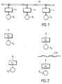
- an MV transmission medium is connected to network interfaces Ia to Ic, respectively connected to Pa to Pc positions.
- This is the classic structure of a network data transmission computing, to which may apply the CSMA / CD protocol already mentioned, in accordance with IEEE 802.3 standard.
- Posts such as Pa are data processing stations (the word treatment is used here in the most basic sense, this treatment can be very simple). All treatments performed in the post are external to the data transmission proper. But there may be in the specific operations item taking into account specifically of the nature and certain applicable conditions data transmission. These are the layers of the protocol.
- the layers of the protocol itself will, on the contrary, govern the transmission of data in its basic conditions, of a in a way that ensures security.
- the stations or stations Pa to Pd are now connected to radio devices Ra to Rd, provided with antennas.
- all the stations can exchange data directly, except stations Rb and Rd, between which there is an OBS obstacle.
- the word “message” here designates a set of data to transmit, of any size.
- the word “weft” or “package” indicates the elementary unit of data transmission, it is ie the block of data that can be transmitted together.
- One of the features of the present invention is to ensure that when a station wishes to transmit a frame, this position be the only one to do so in its scope radio.
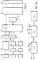
- FIG. 3 illustrates the general structure of a network interface for a station.
- the RE block designates the standardized connection to the IEEE 802 standard, which allows connection to a network output from a computer.
- This connection is for example made with the i82586 integrated circuit sold by INTEL Corporation.
- the RL block is a "local router" whose role will be explained later. Its function is to establish messages to be transmitted, with transmission requests, as well as to collect the messages properly received, and possibly re-direct them.
- ARC block which is the unit of transmission-reception management, depending in particular on collisions.
- An ADF block is added to it, which will allow to correct frequency drifts, by sending artificial messages, when necessary.
- a main channel at the top which is established between a transmit-receive antenna A0, a modulated radio transceiver, for transmission of data, denoted RD, and a circuit CC which has the function, at the transmission, to enhance the corrective code message, and, upon receipt, check the correction of these codes to detect possible errors inside a message (otherwise received normally, i.e. without collision).
- a first lateral channel equipped with an A1 transceiver antenna, a transceiver R1 with fast transmission / reception switching, and RC circuit for radio collision detection.
- GA block which operates as a generator. pseudo-random codes, such codes being used for different purposes according to the invention, on the one hand by the circuit RC, on the other hand by the ARC block already mentioned. RC blocks and ARC are directly interconnected.
- a second channel is represented side with its antenna A2, its receiver R2, and a circuit RP, which allows radio detection of "hidden carriers”.
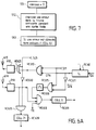
- the ARC block can be broken down into three ARCA blocks, ARCB and ARCC, as illustrated in Figure 3A.
- the ARCA block is responsible for directing and detecting collisions exploit the result.
- the ARCB block is used for the resolution of collisions, and the establishment of confirmatory orders transmitting or receiving data. It will be incorporated to this ARCB block a collision resolution mechanism which can be of any known type.
- the ARCC block will in charge, in conjunction with the ADF block, of ensuring transmission artificial messages.
- FIG. 4A illustrates the conventional format of an ETHERNET message conforms to the IEEE 802.3 standard.
- the present invention provides that this message is completed, if we wish, by the additional indications which appear right in Figure 4B. They include share an indication of relay recipient and relay source, a code called LARA code (this denomination "LARA" being assigned to the new protocol according to the present invention), and a buffer area that can hold information complementary.
- LARA code this denomination "LARA” being assigned to the new protocol according to the present invention
- the buffer zone contains, as shown in Figure 4C, first a code indicating that it is a point-to-point transmission, that is to say from a single transmitting station to a single station recipient, on the other hand an area indicating the number of jumps already made by the frame in the various relays that she suffered from the original transmitter station. This stamp is updated at each jump or relay in the frame.
- a message can be sent by a post to destination of several posts, what will be called a "diffusion".
- the buffer zone is multiplied, to include a code indicating that it is a broadcast, the number of relays, as well as the recipient addresses of different relays 1 to n, one broadcast message number, and hop count performed by the frame in its previous relays.
- each frame is made up two parts, namely the header, and the body of the package.
- the header contains at least the address of the recipient (s), and the address of the sender, as well as some specific traffic information (e.g. whether or not an acknowledgment is required).
- the body of the packet contains the data to be transmitted (file, accused of reception), as well as the end of packet signals.
- These frames or packets are routed one by one from the block RE of FIG. 3.
- the block RL will process these packets, basically in the event that a recipient is not in the radio range of the transmitter; he then proceeds to a modification of the header by adding the address of an intermediate station, as illustrated in FIG. 4B.
- the packets are then taken care of by the ARC block, which decides on emissions, and interrupts them in the event of a collision detected.
- the CC encoder and the RD device are responsible for the actual emission of the frames in ether. When a frame was correctly transmitted without collision, a signal is transmitted to the RE block, to allow taking the next package.
- the block CC will check the correction of received packets; of reference, packets with error will simply be destroyed.
- the RL block determines if the message has arrived at its destination, or if he is in the process of correspondence or relay. A message arrived at destination is transmitted to the RE block, while that a message to be relayed possibly has its header modified taking into account the relay, to return to the ARC block with a view to a reissue.
- the international standard ISO - IEEE 802 provides for a division layered communication functions. Functions located from the antennas to the included ADF block constitute adaptation of radio functions conventionally called "Medium Access Control" layer or MAC. According to the present invention, a new layer is introduced next, which corresponds to block RL, and which one can call layer “membership and routing” or MR. At the RE block, we find the interface layer Classic ETHERNET.
- the aim is to ensure maximum electromagnetic protection to the digital sequence which must pass between a transmitter and receiver; you have to fight the most effectively against parasitic phenomena or multiple paths. On the other hand, it is useless to fight against interference by possible emissions from others network stations, because this is the criterion that will allow to establish the existence of a collision, and then to resolve this one.
- the RD block can work by spread spectrum with a unique code for all stations of the same network, this unique code can be a pseudo-random code common to all stations, and detected by filter adapted to the reception. This is just one example.
- a radio reception will be considered as demodulable if its gain on reception is greater than or equal to a threshold value e d . If the gain is lower, the received signal is considered “received with errors".
- a value E d is defined, which corresponds to reception "in the immediate vicinity” (This is used in particular for routing, described below). This definition of a threshold common to all stations or stations assumes that the reception power is the same for all, which is generally accepted here.
- the function of the DC circuit, in transmission mode, is to transform IEEE 802 standard frames in binary sequences more resistant to transmission errors, thanks in particular to using error correcting codes (e.g. a interlacing, associated with the use of a convolutional code).
- error correcting codes e.g. a interlacing, associated with the use of a convolutional code
- the component renders the initial frame in correcting any transmission errors on the binary sequence received from the radio reception device data (when the latter has demodulable reception).
- This or these codings can be completed with a technique interleaving where, after coding, we modify substantial bit order in each bit sequence sent; so a brief disturbance only affects bits of information that were far apart from each other others in the original sequence. Normal order is fine safe restored after receipt before decoding error corrector.
- CC block there is provided, upstream of its encoder part, a basic device for rapid detection of errors, like staking the frame with parity bits in sufficient quantities.
- error checking parity checking for example
- FIG. 5 for the description, in the form of a method, of the implementation of the invention.
- step 500 marks the wait for the start of a transmission (transmission) or reception.
- step 501 tests whether it is a broadcast or reception.
- step 510 detailed in Figure 6
- step 550 detailed in FIG. 7.
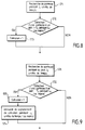
- listening step 530 active if it was at the start of a broadcast, and at contrary to step 570 of passive listening if it were of a reception.
- steps 530 and 570 are detailed respectively in FIGS. 9 and 8.
- listening passive is performed in both cases.
- the station was at the start of transmission.
- the stage 541 determines the presence or absence of a collision. In the presence of a collision, the transmission is interrupted, preferably after inserting a sequence with an error of parity, on special order addressed to the CC block, as shown in step 542. In the absence of a collision, the emission continues as shown in step 543.
- the block CC searches for a possible parity (or other) error in the incoming frame, and this for a fixed period.
- sub-step 553 we pass the COLL12 signal at 1 if such an error is detected.
- step 510 More complex, the detail of step 510 will now be described with reference to Figure 6.
- the pseudo-random generator GA (figure 3) provided a word pseudo-random Gc with Nc bits.
- step 511 a processing index i is initialized to 1, while the variable COLL11 is set to the value 0, representative "false" collision.
- Step 512 consists in taking from the word g c its ith bit, which will be designated by a.
- Step 513 tests whether the bit a is 0 or 1. If it is 1, step 515 consists in transmitting on the first side channel for a time L c . If it is 0, we will on the contrary go to step 514 to listen on the first side channel for the time L c .
- step 516 it is tested whether a gain carrier greater than a threshold value e c has been detected. If yes, it is because another station has transmitted at the same time (on the basis of a different pseudo-random word). In this case, step 517 consists in passing the variable COLL11 to 1.
- step 519 increments the work index i, and we return to 512.
- the final exit is to go to the next step of collision report, which is step 520 in Figure 5.
- the carrier detection of step 516 does not take place immediately from the start of the listening time interval defined in step 514.
- a time l c is preferably expected, so that the detector collisions cannot be abused by the echo of its own broadcasts.
- step 515 is arranged for the transmission of step 515 to appear continuously, when two consecutive bits of the pseudo-random word g c are at one.
- the second stage follows the first, after a silence. This silence is preferably at least equal to L c . In all, the second stage therefore begins (NOT vs +1) * L vs time units after the start of activation of the collision detector automaton.
- this automaton presents at least two states, namely an emission state to signal or "broadcast" the collision and a listening state. He preferably has three states, the listening state can be a listening passive or active listening.
- the global steps 522, respectively 562, of FIG. 5 consist in transmitting on the first side channel a predetermined signal, such as a pure carrier, for J c time units.
- the passive listening of the global step 570 is detailed in FIG. 8: the sub-step 571 consists in listening on the first side channel for J c time units: the sub-step 572 searches on this channel for a carrier having a gain greater than E c , for a substantial duration, at least equal to L c ; if such a carrier is detected during the time thus defined, step 573 validates a collision variable COLL22 at 1.
- each station defines its own (irregular) transmission / reception comb.
- L c is the clock used to define this comb.
- L c must be chosen greater than the time during which we receive echoes after transmission (fading).
- J c is a time (in principle predetermined), chosen sufficient so that, in the presence of a collision, all the stations concerned can be aware of it.
- Steps 531 to 533 thereof are identical to steps 571 to 573 of FIG. 8.
- Active listening simply consists in adding, in the presence of a collision detected in step 533, a step 534 which modulates a carrier signal on the first lateral channel R1, and this, for at least J c units of time, for report a collision.
- FIG. 6A illustrates by way of example a hardware embodiment of what corresponds to step 510 of FIG. 5.
- the antenna A1 and the receiver R1 of FIG. 3 are here broken down into a transmission part A1E, R1E and a reception part A1R, R1R.
- the GA block has constructed a pseudo-random word g c . This word can be stored in a register RC60, receiving clock pulses which define the processing index i.
- the signal S11 is true and the signal S21 false.
- signal S21 is true, in the event of a collision already detected locally, and the transmitter R1E is energized via the OR gate RC625. If he's false, after complementation by the RC630 inverter, we monitors the output of the R1R receiver, via an AND RC635 gate, which determines a collision condition COLL21, stored in RC639 memory, and corresponding to listening (passive, on this figure 6A).
- FIGS. 6B and 6C illustrate a variant where we have split the first side channel into two "first" channels separate sides, suffixed 1 and 2 respectively in their transmission and reception parts. This results in simplifications of circuits.
- FIG. 6B relates to the first step of the PLC, in the case of a station having transmitted.
- the figure 6C concerns the second stage of the automaton, where we have distinguished (simply for illustration) the case S21 of stations which have already recognized the collision, and that S22 of stations that have not yet recognized it.
- the elements of two channels RC635,645 then RC 639,649 are the same.
- an OR function RC660 combines the COLL21 and COLL22 outputs into COLL2.
- the operation is as follows: The two stages S1 and S2 can take place simultaneously: you can listen to R1R2 during the first step, which takes place as before with R1E1 and R1R1 for an active station. Any collision detected forces immediate emission to R1E2.
- the antenna A2 and the radio stage R2 are subdivided into A2E transmission parts, R2E and receiving parts A2R, R2R.
- A2E transmission parts R2E and receiving parts A2R, R2R.
- reception part A0E and RDE we separate its reception part A0E and RDE, and its A0R and RDR transmission part.
- CCE CCE transmission part and its CCR reception part.
- the CCR coder On reception, the CCR coder provides on the one hand data, on the other hand an indication RE that it is receiving (demodulable signals by the RDR stage).
- the RE signal forces the emission of a busy signal by the R2E stage of the second lateral channel, signifying that the ether is occupied, and this for all stations within radio range.
- An ET LL200 logic function receives the transmission order from base TR, and the signal BT complemented (the complementation is manifested by a small circle on the door entrance LL100).
- the basic transmission order TR therefore does not become an order confirmation of TRE transmission only if no busy signal BT is not received. If TRE is true, the RDE transmitter stage is authorized to send packets or data frames, whether receives after suitable transformation from the encoder circuit CCE emission.
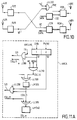
- FIG. 11A describes the ARCA part of the ARC block in Figure 3.
- An ARCA10 sequencer defines steps 1 and 2, depending for example a DEB start logic signal and a signal TR / RE logic indicating whether it is a broadcast or a reception.
- an ET LL310 door intervenes. It has an input receiving the representative RE signal reception, an input receiving the signal S1 and a third input receiving, complemented, the signal REOK. Receiving an incorrect frame will establish a signal COLL12 detected collision logic, representative of a collision on reception, attributable to other stations.
- the device managing the transmissions / receptions pseudo-random alternations on the first side channel can be deleted.
- FIG. 11B illustrates in simplified form the functions of collision resolution.
- ARCB 20 PLC which operates according to a known collision resolution method, such as BEB ("Binary Exponential Backoff" or Exponential Shift binary).
- BEB Binary Exponential Backoff
- Exponential Shift binary Exponential Shift binary
- it can be one of the methods recently introduced to achieve collision resolution deterministic, that is to say in limited time.
- this is the collision resolution process described in the aforementioned Patent Application.
- the switch ARCB50 in Figure 11B also receives signals from an additional ARCC60 memory, which contains artificial messages to which we will return later. he naturally associated with it is a request signal from additional transmission REQ_TR_SUP.
- the Applicant therefore considered it desirable, when the insufficient radio traffic to ensure sufficient time brief synchronization of receptions on broadcasts, artificially increase this traffic by artificial messages.
- the Claimant considered that it had to ensure an appropriate statistical balance of transmission-reception : in other words, the sum of the natural and artificial traffic flows equals one quantity established in advance. But it also has to be property is checked in each of the cells (areas of range) surrounding each station or station. The skilled person will then understand that the theoretical resolution of this problem involves calculations of enormous complexity, that it is excluded to implement in real time and in situ without compromising seriously the functioning of the network.
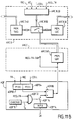
- the ADF block is responsible for determining how to generate the transmission of artificial messages.
- This ADF block (FIG. 11B) is articulated on an ADF70 chronometric circuit, which defines instants of control with a periodicity T A (step 700, fig.12). For example, pulses of period T A are applied to an AND function ADF72, which also receives the local transmission request signal, complemented, REQ_TR / (the final slash marks a complemented signal). If, at time T A , there is no local transmission request (test 702), then we will close the switch ADF76 to authorize an ADF74 register to supply a pseudo-random number NPA, which will have been obtained (704) from the generator GA of FIG. 3. This pseudo-random number is applied to the negative input of a digital comparator ADF88.
- the set of blocks ADF82 and ADF84 maintains a probability quantity p (t).
- the quantity p (t) is transmitted at the positive input of the digital comparator ADF88. Yes the comparator indicates (test 706) that g (t) is less than p (t), then we will produce the additional transmission request REQ_TR_SUP, to request the transmission of artificial messages (708).
- the quantity p (t) is defined repeatedly from its previous value and observing a change channel status.
- the first function of the block RL is therefore to examine the recipient address contained in the header of Figure 4A.
- the RL block then consults its local routing table. If necessary, it will modify the header of the frame, so that it is transmitted at an intermediate station that is within radio range.
- the format of the packet or frame is then that of FIG. 4B.
- the complete frame is sent to the ARC block, to process the broadcast, resolving any collisions.
- the block ARC On reception, when a frame is received without error, the block ARC transmits it to the RL block, which first determines whether the transit or relay address contained in the header is well that of his local station. If this condition is not checked, the frame can be skipped.
- the transit recipient is the same as the recipient real, it is a frame arrived at destination, and this one is directly transmitted to the RE block, after correction of its header to switch from the format of FIG. 4B to the format of Figure 4A.
- the router will act exactly as if the frame had been obtained from the RE connection, with transmission request : it consults its local routing table, and modifies new frame header, to write a new one intermediate station, or the final recipient, after whereby the frame is returned to the ARC block. It is possible that a copy be submitted to the RE block for information.
- This update day can be driven from normally received frames of the ARC block.
- Each frame normally received includes an indication of its immediate transmitter. It is therefore possible for the RL block to maintain permanently a table of neighboring posts or stations that he receives. In addition, at regular intervals, the RL block will create a spontaneous frame, by which it diffuses to other stations within its radio range at least part of the contents of its routing table (stations it receives). This spontaneous weft can be incorporated into artificial traffic when created. It can be created by authority when there is no need for artificial traffic.
- the stations which are in the two registers are in relation to "symmetrical range" with this post. Routing can only take place using stations checking this symmetrical range condition.
- each extension A can communicate directly (1 transmission) with its "symmetrical range” counterparts, indirectly (2 transmissions) with other stations at "symmetrical range” of the first, which serve as relays, And so on. It is conceivable to set a limit on number of relay stations admitted, which will be called below "number of jumps".
- topological directory for each station.
- This directory is a rectangular matrix or two entries with for example in columns the station numbers registered in the emission register of A, i.e. who receive the current position directly, and on the ordinates numbers of all stations that are accessible from of the current position. Each cell of this table will contain the number of hops required to reach the station ultimately aimed.
- the message format buffer in Figure 4B includes at least a code at the base indicating that it is point-to-point transmission, that is to say interesting only an initial transmitting station and a station final receiver, with the expected number of jumps to go from one to the other.
- each station transmits at intervals its routing table, which allows verification the consistency of the different routing tables of the different stations.
- the broadcasting table collects the station numbers at symmetrical scope, or a subset of these (this subset having to verify the property that it still exists a station in the broadcast table that allows to reach any of the stations on the network, or any stations targeted by the broadcast).
- the broadcasts directory stores the numbers of dissemination of a number of the latest communications in broadcast that have reached the local station.
- the Applicant considers that it is then advantageous to use the format of Figure 4D, where the buffer includes a code distribution, a number of targeted relays, different recipients, a broadcast number and a number of eligible hops.
- the invention can be modified in different ways.
- a side channel can be used to detect collisions, for example as described above in reference to the busy signal, but without using the collision reporting through a side channel.
- the use of the busy signal can be done without use collision reporting by a side channel.
Landscapes
- Engineering & Computer Science (AREA)
- Computer Networks & Wireless Communication (AREA)
- Signal Processing (AREA)
- Small-Scale Networks (AREA)
- Mobile Radio Communication Systems (AREA)
- Radio Relay Systems (AREA)
Applications Claiming Priority (3)
| Application Number | Priority Date | Filing Date | Title |
|---|---|---|---|
| FR9204032 | 1992-04-02 | ||
| FR9204032A FR2689658B1 (fr) | 1992-04-02 | 1992-04-02 | Installation de transmission de donnees, du type reseau radio, et procede correspondant. |
| EP93907909A EP0634069B1 (de) | 1992-04-02 | 1993-03-30 | Anlage und verfahren zur uebertragung von daten in einem funknetz |
Related Parent Applications (1)
| Application Number | Title | Priority Date | Filing Date |
|---|---|---|---|
| EP93907909A Division EP0634069B1 (de) | 1992-04-02 | 1993-03-30 | Anlage und verfahren zur uebertragung von daten in einem funknetz |
Publications (3)
| Publication Number | Publication Date |
|---|---|
| EP0862298A2 true EP0862298A2 (de) | 1998-09-02 |
| EP0862298A3 EP0862298A3 (de) | 2006-08-23 |
| EP0862298B1 EP0862298B1 (de) | 2010-01-20 |
Family
ID=9428409
Family Applications (3)
| Application Number | Title | Priority Date | Filing Date |
|---|---|---|---|
| EP98102754A Expired - Lifetime EP0849914B1 (de) | 1992-04-02 | 1993-03-30 | Kollisionserkennung durch die Übertragung von Daten über ein Funknetz |
| EP93907909A Expired - Lifetime EP0634069B1 (de) | 1992-04-02 | 1993-03-30 | Anlage und verfahren zur uebertragung von daten in einem funknetz |
| EP98102755A Expired - Lifetime EP0862298B1 (de) | 1992-04-02 | 1993-03-30 | Einrichtung eines Funk-Datenübertragungsnetzes mit Leitweglenkung |
Family Applications Before (2)
| Application Number | Title | Priority Date | Filing Date |
|---|---|---|---|
| EP98102754A Expired - Lifetime EP0849914B1 (de) | 1992-04-02 | 1993-03-30 | Kollisionserkennung durch die Übertragung von Daten über ein Funknetz |
| EP93907909A Expired - Lifetime EP0634069B1 (de) | 1992-04-02 | 1993-03-30 | Anlage und verfahren zur uebertragung von daten in einem funknetz |
Country Status (7)
| Country | Link |
|---|---|
| US (2) | US5689510A (de) |
| EP (3) | EP0849914B1 (de) |
| JP (1) | JP3432223B2 (de) |
| CA (1) | CA2133432C (de) |
| DE (3) | DE69323074T2 (de) |
| FR (1) | FR2689658B1 (de) |
| WO (1) | WO1993020636A1 (de) |
Families Citing this family (9)
| Publication number | Priority date | Publication date | Assignee | Title |
|---|---|---|---|---|
| FR2689658B1 (fr) * | 1992-04-02 | 1995-10-20 | Inst Nat Rech Inf Automat | Installation de transmission de donnees, du type reseau radio, et procede correspondant. |
| WO1994017616A1 (fr) * | 1993-01-26 | 1994-08-04 | Inria Institut National De Recherche En Informatique Et En Automatique | Installation de transmission de donnees, du type reseau radio, et procede correspondant |
| JP3406443B2 (ja) * | 1995-12-08 | 2003-05-12 | 日本ビクター株式会社 | 無線伝送装置 |
| US6130894A (en) * | 1998-03-09 | 2000-10-10 | Broadcom Homenetworking, Inc. | Off-line broadband network interface |
| EP1232567B1 (de) * | 1999-11-03 | 2004-03-03 | Stratos Global Limited | Anrufumleitungssystem |
| US7333504B2 (en) * | 2001-03-08 | 2008-02-19 | Honeywell International Inc. | Simultaneous serial transmission of messages with data field arbitration |
| US7274731B2 (en) * | 2001-11-09 | 2007-09-25 | Adc Dsl Systems, Inc. | Non-chronological system statistics |
| US8085806B2 (en) * | 2003-09-26 | 2011-12-27 | Agere Systems Inc. | Method and apparatus for detecting a collision in a carrier sense multiple access wireless system |
| RU2736332C1 (ru) * | 2019-12-30 | 2020-11-16 | федеральное государственное автономное образовательное учреждение высшего образования "Санкт-Петербургский политехнический университет Петра Великого" (ФГАОУ ВО "СПбПУ") | Способ организации подключения к сети опорных датчиков по информационному каналу |
Family Cites Families (7)
| Publication number | Priority date | Publication date | Assignee | Title |
|---|---|---|---|---|
| US4683471A (en) * | 1985-01-30 | 1987-07-28 | Hughes Aircraft Company | Data bus pilot tone |
| US4665519A (en) * | 1985-11-04 | 1987-05-12 | Electronic Systems Technology, Inc. | Wireless computer modem |
| GB8628824D0 (en) * | 1986-12-02 | 1987-01-07 | Plessey Co Plc | Communication system |
| US5162791A (en) * | 1989-10-02 | 1992-11-10 | Codenoll Technology Corporation | Collision detection using code rule violations of the manchester code |
| US5040175A (en) * | 1990-04-11 | 1991-08-13 | Ncr Corporation | Wireless information transmission system |
| FR2689658B1 (fr) * | 1992-04-02 | 1995-10-20 | Inst Nat Rech Inf Automat | Installation de transmission de donnees, du type reseau radio, et procede correspondant. |
| US5418784A (en) * | 1993-06-30 | 1995-05-23 | Digital Equipment Corporation | Method and apparatus for use in a network of the ethernet type, to improve fairness by controlling the interpacket gap in the event of channel capture |
-
1992
- 1992-04-02 FR FR9204032A patent/FR2689658B1/fr not_active Expired - Fee Related
-
1993
- 1993-03-30 EP EP98102754A patent/EP0849914B1/de not_active Expired - Lifetime
- 1993-03-30 DE DE69323074T patent/DE69323074T2/de not_active Expired - Fee Related
- 1993-03-30 DE DE69334314T patent/DE69334314D1/de not_active Expired - Fee Related
- 1993-03-30 CA CA002133432A patent/CA2133432C/fr not_active Expired - Fee Related
- 1993-03-30 WO PCT/FR1993/000317 patent/WO1993020636A1/fr not_active Ceased
- 1993-03-30 JP JP51716093A patent/JP3432223B2/ja not_active Expired - Fee Related
- 1993-03-30 US US08/307,579 patent/US5689510A/en not_active Expired - Lifetime
- 1993-03-30 DE DE69334316T patent/DE69334316D1/de not_active Expired - Fee Related
- 1993-03-30 EP EP93907909A patent/EP0634069B1/de not_active Expired - Lifetime
- 1993-03-30 EP EP98102755A patent/EP0862298B1/de not_active Expired - Lifetime
-
1997
- 1997-11-07 US US08/966,016 patent/US6023457A/en not_active Expired - Lifetime
Also Published As
| Publication number | Publication date |
|---|---|
| US5689510A (en) | 1997-11-18 |
| WO1993020636A1 (fr) | 1993-10-14 |
| FR2689658B1 (fr) | 1995-10-20 |
| CA2133432C (fr) | 2003-10-14 |
| EP0849914A3 (de) | 2006-08-23 |
| DE69323074T2 (de) | 1999-06-02 |
| EP0862298A3 (de) | 2006-08-23 |
| FR2689658A1 (fr) | 1993-10-08 |
| EP0634069A1 (de) | 1995-01-18 |
| EP0849914A2 (de) | 1998-06-24 |
| EP0862298B1 (de) | 2010-01-20 |
| EP0849914B1 (de) | 2010-01-20 |
| EP0634069B1 (de) | 1999-01-13 |
| JP3432223B2 (ja) | 2003-08-04 |
| US6023457A (en) | 2000-02-08 |
| CA2133432A1 (fr) | 1993-10-14 |
| JPH09500767A (ja) | 1997-01-21 |
| DE69334314D1 (de) | 2010-03-11 |
| DE69323074D1 (de) | 1999-02-25 |
| DE69334316D1 (de) | 2010-03-11 |
Similar Documents
| Publication | Publication Date | Title |
|---|---|---|
| FR2669798A1 (fr) | Dispositif pour la transmission d'informations synchrones par un reseau asynchrone, notamment un reseau atm. | |
| FR2579341A1 (fr) | Reseau local de transmission de donnees comportant un systeme de detection de signaux, evitant des collisions et procede de transfert de donnees dans un tel reseau | |
| FR2628915A1 (fr) | Testeur de reseau local a methode d'acces a test de porteuse et detection de collisions (csma/cd) | |
| EP2337284B1 (de) | Sicheres Routingprotokoll | |
| FR2718306A1 (fr) | Procédé d'adaptation de l'interface air, dans un système de radiocommunication vers des mobiles. | |
| FR2825208A1 (fr) | Procede d'attribution de ressources en communication dans un systeme de telecommunications du type mf-tdma | |
| EP0642285A1 (de) | Kanalaufteilungsverfahren durch kontrollierten Zeitschlitzdiebstahl in einem gemultiplexten Funkkommunikationssystem, sowie entsprechendes Endgerät und Infrastruktur | |
| FR2579342A1 (fr) | Reseau local de transmission de donnees et procede d'affectation automatique d'adresses a des dispositifs de traitement de donnees de ce reseau | |
| FR2651625A1 (fr) | Systeme de telecommunications par paquets. | |
| WO2005025089A1 (fr) | Gestion de l’acces a un reseau de communications a acces aleatoire | |
| EP1794934A1 (de) | Verfahren, vorrichtung und programm zur detektion einer nichtautorisierten verbindung zu zugangspunkten | |
| EP0517609A1 (de) | Verfahren und Arbitrierungsbus zur Übertragung von seriellen Daten | |
| FR2992620A1 (fr) | Train et procede de determination de la composition d'un tel train en securite | |
| EP0407279A1 (de) | Kommunikationsnetz zwischen Teilnehmereinrichtungen | |
| EP0862298B1 (de) | Einrichtung eines Funk-Datenübertragungsnetzes mit Leitweglenkung | |
| FR2466921A1 (fr) | Appareil d'affectation et de selection de parties de canaux de transmission de donnees | |
| FR2543767A1 (fr) | Dispositif d'echange de messages codes entre stations | |
| EP0784390B1 (de) | Verfahren zür Überwachungsprogrammänderung in einer Empfangsanlage einer Richtfunkstrecke, Empfangsanlage und entsprechendes Richtfunk-Datenübertragungssystem | |
| FR2736230A1 (fr) | Installation du type reseau radio de transmission de donnees avec rouage | |
| FR2741220A1 (fr) | Systeme de surveillance et de gestion d'un reseau d'acces point-multipoint | |
| EP0742977B1 (de) | Impulsfolgen-übertragungssystem | |
| FR2689657A1 (fr) | Installation de transmission de données, du type réseau radio, et procédé correspondant. | |
| CA2875219A1 (fr) | Procede de selection de noeuds servant de relais multipoints | |
| EP0637417B1 (de) | Datenübertragungseinrichtung und verfahren für funknetz | |
| FR3126578A1 (fr) | Procede de regulation destine a resorber un engorgement d’un reseau maille de communication par courants porteurs en ligne et radio |
Legal Events
| Date | Code | Title | Description |
|---|---|---|---|
| PUAI | Public reference made under article 153(3) epc to a published international application that has entered the european phase |
Free format text: ORIGINAL CODE: 0009012 |
|
| 17P | Request for examination filed |
Effective date: 19980218 |
|
| AC | Divisional application: reference to earlier application |
Ref document number: 634069 Country of ref document: EP |
|
| AK | Designated contracting states |
Kind code of ref document: A2 Designated state(s): DE ES GB IT NL SE |
|
| PUAL | Search report despatched |
Free format text: ORIGINAL CODE: 0009013 |
|
| AK | Designated contracting states |
Kind code of ref document: A3 Designated state(s): DE ES GB IT NL SE |
|
| RIC1 | Information provided on ipc code assigned before grant |
Ipc: H04L 12/56 20060101ALI20060714BHEP Ipc: H04L 12/413 20060101AFI20060714BHEP |
|
| GRAP | Despatch of communication of intention to grant a patent |
Free format text: ORIGINAL CODE: EPIDOSNIGR1 |
|
| GRAS | Grant fee paid |
Free format text: ORIGINAL CODE: EPIDOSNIGR3 |
|
| GRAA | (expected) grant |
Free format text: ORIGINAL CODE: 0009210 |
|
| AC | Divisional application: reference to earlier application |
Ref document number: 0634069 Country of ref document: EP Kind code of ref document: P |
|
| AK | Designated contracting states |
Kind code of ref document: B1 Designated state(s): DE ES GB IT NL SE |
|
| REG | Reference to a national code |
Ref country code: GB Ref legal event code: FG4D Free format text: NOT ENGLISH |
|
| REF | Corresponds to: |
Ref document number: 69334316 Country of ref document: DE Date of ref document: 20100311 Kind code of ref document: P |
|
| REG | Reference to a national code |
Ref country code: NL Ref legal event code: VDEP Effective date: 20100120 |
|
| PG25 | Lapsed in a contracting state [announced via postgrant information from national office to epo] |
Ref country code: NL Free format text: LAPSE BECAUSE OF FAILURE TO SUBMIT A TRANSLATION OF THE DESCRIPTION OR TO PAY THE FEE WITHIN THE PRESCRIBED TIME-LIMIT Effective date: 20100120 Ref country code: ES Free format text: LAPSE BECAUSE OF FAILURE TO SUBMIT A TRANSLATION OF THE DESCRIPTION OR TO PAY THE FEE WITHIN THE PRESCRIBED TIME-LIMIT Effective date: 20100501 |
|
| PG25 | Lapsed in a contracting state [announced via postgrant information from national office to epo] |
Ref country code: SE Free format text: LAPSE BECAUSE OF FAILURE TO SUBMIT A TRANSLATION OF THE DESCRIPTION OR TO PAY THE FEE WITHIN THE PRESCRIBED TIME-LIMIT Effective date: 20100120 |
|
| PLBE | No opposition filed within time limit |
Free format text: ORIGINAL CODE: 0009261 |
|
| STAA | Information on the status of an ep patent application or granted ep patent |
Free format text: STATUS: NO OPPOSITION FILED WITHIN TIME LIMIT |
|
| 26N | No opposition filed |
Effective date: 20101021 |
|
| GBPC | Gb: european patent ceased through non-payment of renewal fee |
Effective date: 20100420 |
|
| PG25 | Lapsed in a contracting state [announced via postgrant information from national office to epo] |
Ref country code: DE Free format text: LAPSE BECAUSE OF NON-PAYMENT OF DUE FEES Effective date: 20101001 |
|
| PG25 | Lapsed in a contracting state [announced via postgrant information from national office to epo] |
Ref country code: IT Free format text: LAPSE BECAUSE OF FAILURE TO SUBMIT A TRANSLATION OF THE DESCRIPTION OR TO PAY THE FEE WITHIN THE PRESCRIBED TIME-LIMIT Effective date: 20100120 Ref country code: GB Free format text: LAPSE BECAUSE OF NON-PAYMENT OF DUE FEES Effective date: 20100420 |