EP0862308A2 - Herausziehbare Taste für eine Tastatur - Google Patents
Herausziehbare Taste für eine Tastatur Download PDFInfo
- Publication number
- EP0862308A2 EP0862308A2 EP98301156A EP98301156A EP0862308A2 EP 0862308 A2 EP0862308 A2 EP 0862308A2 EP 98301156 A EP98301156 A EP 98301156A EP 98301156 A EP98301156 A EP 98301156A EP 0862308 A2 EP0862308 A2 EP 0862308A2
- Authority
- EP
- European Patent Office
- Prior art keywords
- button
- wall
- opening
- switch
- pair
- Prior art date
- Legal status (The legal status is an assumption and is not a legal conclusion. Google has not performed a legal analysis and makes no representation as to the accuracy of the status listed.)
- Withdrawn
Links
Images
Classifications
-
- H—ELECTRICITY
- H01—ELECTRIC ELEMENTS
- H01H—ELECTRIC SWITCHES; RELAYS; SELECTORS; EMERGENCY PROTECTIVE DEVICES
- H01H13/00—Switches having rectilinearly-movable operating part or parts adapted for pushing or pulling in one direction only, e.g. push-button switch
- H01H13/70—Switches having rectilinearly-movable operating part or parts adapted for pushing or pulling in one direction only, e.g. push-button switch having a plurality of operating members associated with different sets of contacts, e.g. keyboard
- H01H13/702—Switches having rectilinearly-movable operating part or parts adapted for pushing or pulling in one direction only, e.g. push-button switch having a plurality of operating members associated with different sets of contacts, e.g. keyboard with contacts carried by or formed from layers in a multilayer structure, e.g. membrane switches
- H01H13/705—Switches having rectilinearly-movable operating part or parts adapted for pushing or pulling in one direction only, e.g. push-button switch having a plurality of operating members associated with different sets of contacts, e.g. keyboard with contacts carried by or formed from layers in a multilayer structure, e.g. membrane switches characterised by construction, mounting or arrangement of operating parts, e.g. push-buttons or keys
-
- H—ELECTRICITY
- H04—ELECTRIC COMMUNICATION TECHNIQUE
- H04M—TELEPHONIC COMMUNICATION
- H04M1/00—Substation equipment, e.g. for use by subscribers
- H04M1/02—Constructional features of telephone sets
- H04M1/23—Construction or mounting of dials or of equivalent devices; Means for facilitating the use thereof
-
- H—ELECTRICITY
- H01—ELECTRIC ELEMENTS
- H01H—ELECTRIC SWITCHES; RELAYS; SELECTORS; EMERGENCY PROTECTIVE DEVICES
- H01H2221/00—Actuators
- H01H2221/066—Actuators replaceable
-
- H—ELECTRICITY
- H01—ELECTRIC ELEMENTS
- H01H—ELECTRIC SWITCHES; RELAYS; SELECTORS; EMERGENCY PROTECTIVE DEVICES
- H01H2231/00—Applications
- H01H2231/022—Telephone handset
Definitions
- This invention relates to keypads and, more particularly, to a button which is removable from and insertable into the keypad from the exterior of a housing containing the keypad.
- Telephones have keypads which include dial buttons and feature buttons, where the buttons are typically labeled with the dial number or feature identification.
- the features may have different identifications corresponding to the different languages.
- field upgrades as a result of new software may change the features available on the telephone set. It would therefore be desirable to be able to change the keypad buttons to accommodate different labeling.
- a common telephone keypad construction includes a printed circuit board having spaced switch terminals thereon.
- a rubber dome membrane is positioned over the circuit board with carbon pills in aligned registry over pairs of the switch terminals so that depression of a rubber dome and its associated carbon pill results in the bridging of the associated spaced switch terminals (i.e., closure of the associated switch).
- the rubber dome is formed with an upwardly extending tower above the carbon pill and a keypad button lightly frictionally engages this tower.
- the keypad housing is formed with an array of openings in positions corresponding to the positions of the switches and is placed over the membrane with the buttons extending through respective ones of the openings. The buttons and the housing have interfering structure so that the buttons cannot be removed upwardly from the housing.
- a keypad wherein the buttons can be removed and inserted without requiring any disassembly and subsequent reassembly.
- the keypad comprises a switch having an upwardly biased actuator and a housing having an upper planar surface positioned over the switch and with an opening in registration with the switch actuator.
- the opening is defined by a wall of the housing extending from the surface toward the switch, the wall having a lower edge portion substantially parallel to the surface.
- the keypad further comprises a removable button insertable through the opening from the surface for cooperation with the switch actuator.
- the button is of unitary construction and includes a top wall engagable by the user, an actuation member extending downwardly from the top wall and adapted for engagement with the switch actuator, and a side wall extending downwardly from the top wall and surrounding the actuation member.
- the button periphery defined by the side wall conforms to the periphery of the opening defined by the housing wall.
- a pair of opposed resilient fingers are formed in the button side wall on opposite sides of the actuation member.
- Each of the fingers extends downwardly within the thickness of the side wall and terminates in an outwardly extending flange which has its lower surface chamfered upwardly and outwardly so that when the button is inserted into the opening toward the switch, each finger deflects inwardly until the flange passes the lower edge portion of the housing wall and then moves outwardly, thereby providing resistance to inadvertent removal of the button from the opening while allowing the user to deflect the finger inwardly to effect removal of the button.
- the construction is such that when the flanges are below the lower edge portions of the housing wall the actuation member engages the switch actuator, and in the absence of user engagement of the button top wall the upward bias of the switch actuator maintains the upper surfaces of the flanges against the housing wall lower edge portions and the button top wall above the housing surface.
- the removable button is of unitary construction, preferably of molded resilient plastic material.
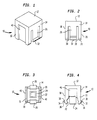
- the button 10 includes a top wall 12 engagable by a finger of a user.
- the top wall 12 is rectangular and there are four side walls 14, 16, 18, 20 extending downwardly from the top wall 12 to form an interior cavity 22.
- the plane of the top wall 12 is orthogonal to the planes of the side walls 14, 16, 18, 20, but it is understood that the top wall 12 can be slanted, can be concave, can be convex, or have any desired topography.
- actuation member 24 Extending downwardly from the top wall 12 within the cavity 22 is an actuation member 24, the purpose of which will be described in full detail hereinafter. Suffice it to say at this point that the illustrated actuation member 24 is a four-sided hollow tubular structure whose walls are parallel to the side walls 14, 16, 18, 20, it being understood that other shapes, such as cylindrical, are possible for the actuation member 24.
- the fingers 26, 28 extend downwardly within the thickness of their respective side walls from a region below the top wall 12.
- the finger 26 may be formed from the side wall 14 by providing a pair of flanking parallel and equal length slits 30 which extend upwardly from the bottom edge 31 of the button 10.
- the fingers 26, 28 terminate at their lower ends in outwardly extending flanges 32, 34, respectively.
- the lower surface 36 of the flange 32 is chamfered upwardly and outwardly and the upper surface 38 of the flange 32 is chamfered downwardly and outwardly.
- the flange 34 is similarly shaped.
- the side wall 16 is formed with a depression 40 which terminates closely adjacent the top wall 12.
- a similar depression (not shown) is formed in the opposed non-adjacent side wall 20.
- the depression 40 extends all the way down the side wall 16 to the bottom edge 31 of the button 10.
- the corresponding depression 42 has a relatively small extent down the side wall 16. The function of the depressions 40, 42 will be described in full detail hereinafter.
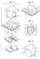
- the removable button 10 is designed to be used in a keypad such that user depression of the button 10 results in closure of a switch.
- the illustrative keypad environment includes a printed circuit board 44 having spaced switch terminals 46, 48 deposited or otherwise provided thereon. Overlying the circuit board 44 is a rubber dome membrane 50.
- the membrane 50 is unitarily formed with an upwardly biased dome 52 and a tower 54 extending upwardly from the dome 52. Captured within a cavity on the underside of the dome 52 is a carbon pill 56.
- the membrane 50 is positioned over the circuit board 44 so that the carbon pill 56 is in aligned registry over the switch terminals 46, 48.
- the circuit board 44 and the membrane 50 are contained within a housing having an upper planar surface 58 and an opening 60 over the aforedescribed switch.
- the opening 60 is centrally positioned over the dome 52.
- the opening 60 is rectangular and is defined by the side walls 62, 64, 66, 68, extending downwardly from the upper surface 58.
- the side walls 62, 66 have respective lower edge portions 70, 72 substantially parallel to the surface 58. These lower edge portions 70, 72 cooperate with the flanges 32, 34, respectively, as will be described in full detail hereinafter.
- the actuation member 24 of the button 10 lightly frictionally engages the tower 54 of the membrane 50, with the tower 54 fitting within the interior of the actuation member 24.
- Depression of the button 10 by the operator exerting a downward pressure on the top wall 12 results in the lower edge of the actuation member 24 pressing downwardly on the dome 52, deforming the dome 52 and causing the carbon pill 56 to contact and bridge the spaced switch terminals 46, 48.
- Release of the downward pressure on the top wall 12 results in the dome 52 returning to its original shape, pulling the carbon pill 56 away from the switch terminals 46, 48, thereby opening the switch and at the same time moving the button 10 upwardly.
- the button 10 is placed within the opening 60 and pushed downwardly.
- the size of the button 10 and the size of the opening 60 are such that the button 10, with the exception of the flanges 32, 34 fits with slight clearance within the opening 60, the flanges 32, 34 extending outwardly beyond the periphery of the opening 60.
- the button 10 is placed over the opening 60 and pushed downwardly, the lower surfaces 36 of the flanges 32, 34 engage the periphery of the opening 60 at the upper corners of the walls 62, 66.
- the dome 52 exerts insufficient upward force to move the flanges 32, 34 from their positions of engagement with the lower edge portions 70, 72, thereby maintaining the button 10 with its top wall 12 extending above the upper surface 58 of the housing ( Figure 6) and the switch open.
- the upper surfaces 38 of the flanges 32, 34 engage the lower edge portions 70, 72 to provide resistance against inadvertent removal of the button 10, the upward biasing force of the dome 52 being insufficient to cause inward deflection of the fingers 26, 28.
- the top wall 12 of the button 10 when the top wall 12 of the button 10 is not engaged by a finger of a user, the top wall 12 is above the upper surface 58 of the housing, exposing upper regions of the side walls 14, 16, 18, 20.
- the dimensions of all of the elements are such that at least a portion of the depressions 40, 42 are exposed when the button 10 is in its non-engaged position. These portions of the depressions 40, 42 allow the user to firmly engage the side walls 16, 20 when it is desired to remove the button 10.
- the button 10 is gripped and pulled upwardly, the downward and outward chamfering of the upper surfaces 38 of the flanges 32, 34 engaging the inner corners of the lower edge portions 70, 72 so that the fingers 26, 28 are deflected inwardly to allow the flanges 32, 34 to move within the periphery of the opening 60 and slide against the inner surfaces of the walls 62, 66.
- the flanges 32, 34 resist inadvertent removal of the button 10, when desired the button 10 is readily removable and replaceable.
Landscapes
- Engineering & Computer Science (AREA)
- Signal Processing (AREA)
- Telephone Set Structure (AREA)
- Push-Button Switches (AREA)
- Input From Keyboards Or The Like (AREA)
Applications Claiming Priority (2)
| Application Number | Priority Date | Filing Date | Title |
|---|---|---|---|
| US805185 | 1997-02-27 | ||
| US08/805,185 US5907612A (en) | 1997-02-27 | 1997-02-27 | Removable button for a keypad |
Publications (2)
| Publication Number | Publication Date |
|---|---|
| EP0862308A2 true EP0862308A2 (de) | 1998-09-02 |
| EP0862308A3 EP0862308A3 (de) | 2001-03-07 |
Family
ID=25190878
Family Applications (1)
| Application Number | Title | Priority Date | Filing Date |
|---|---|---|---|
| EP98301156A Withdrawn EP0862308A3 (de) | 1997-02-27 | 1998-02-17 | Herausziehbare Taste für eine Tastatur |
Country Status (5)
| Country | Link |
|---|---|
| US (1) | US5907612A (de) |
| EP (1) | EP0862308A3 (de) |
| JP (1) | JPH10255585A (de) |
| CA (1) | CA2227593C (de) |
| TW (1) | TW417056B (de) |
Cited By (2)
| Publication number | Priority date | Publication date | Assignee | Title |
|---|---|---|---|---|
| WO2002093599A1 (en) * | 2001-05-11 | 2002-11-21 | Fairlight Esp Pty Ltd | A switch assembly |
| EP1417674A4 (de) * | 2002-04-30 | 2007-08-08 | Nokia Corp | Tastenmatte |
Families Citing this family (15)
| Publication number | Priority date | Publication date | Assignee | Title |
|---|---|---|---|---|
| US6171003B1 (en) * | 1999-09-22 | 2001-01-09 | Behavior Tech Computer Corp. | Low noise key structure of computer keyboard |
| US6204462B1 (en) * | 2000-03-28 | 2001-03-20 | Silitek Corporation | Stable keyswitch |
| US6660948B2 (en) * | 2001-02-28 | 2003-12-09 | Vip Investments Ltd. | Switch matrix |
| US6965511B2 (en) * | 2001-10-10 | 2005-11-15 | Hewlett-Packard Development Company, L.P. | System and method for personalizing an electrical device |
| KR20040026563A (ko) * | 2002-09-25 | 2004-03-31 | 엘지전자 주식회사 | 이동통신 단말기의 키패드 어셈블리 |
| DE202005011033U1 (de) * | 2005-07-13 | 2005-11-03 | Trw Automotive Electronics & Components Gmbh & Co. Kg | Bedienelement |
| KR101175657B1 (ko) * | 2005-11-21 | 2012-08-24 | 엘지전자 주식회사 | 키패드 어셈블리와 그 키패드 어셈블리를 갖는 휴대 단말기 |
| CN101604588B (zh) * | 2009-07-09 | 2012-12-12 | 旭丽电子(广州)有限公司 | 薄型按键结构 |
| WO2011021059A2 (es) * | 2009-08-19 | 2011-02-24 | Carlos Bartning Diaz | Tapa desechable para garrafón, con dosificador regulable integrado y flujo continuado del liquido y procedimiento de operación |
| JP5729433B2 (ja) * | 2013-08-09 | 2015-06-03 | オムロン株式会社 | スイッチおよびこれを用いたキーボード |
| JP3212919U (ja) * | 2014-08-08 | 2017-10-12 | アップル インコーポレイテッド | キーボード |
| US9625936B2 (en) | 2015-03-05 | 2017-04-18 | Snap-On Incorporated | Integrated seal for control button |
| US9938996B2 (en) * | 2015-03-05 | 2018-04-10 | Snap-On Incorporated | Control button retention mechanism |
| CN105355507B (zh) * | 2015-11-04 | 2018-11-16 | 平高集团有限公司 | 高压断路器及其喷口 |
| CN112429071A (zh) * | 2020-11-30 | 2021-03-02 | 奇瑞商用车(安徽)有限公司 | 方向盘集成控制面板及车辆 |
Family Cites Families (3)
| Publication number | Priority date | Publication date | Assignee | Title |
|---|---|---|---|---|
| JPS59195632U (ja) * | 1983-06-15 | 1984-12-26 | 日通工株式会社 | 押ボタンスイツチ |
| US5283408A (en) * | 1992-08-04 | 1994-02-01 | Silitek Corporation | Structure of key switch |
| KR970004399B1 (en) * | 1993-07-02 | 1997-03-27 | B T C Korea Co Ltd | Keyboard |
-
1997
- 1997-02-27 US US08/805,185 patent/US5907612A/en not_active Expired - Lifetime
-
1998
- 1998-01-21 CA CA002227593A patent/CA2227593C/en not_active Expired - Fee Related
- 1998-01-22 TW TW087100854A patent/TW417056B/zh not_active IP Right Cessation
- 1998-02-17 EP EP98301156A patent/EP0862308A3/de not_active Withdrawn
- 1998-02-20 JP JP10038655A patent/JPH10255585A/ja active Pending
Cited By (3)
| Publication number | Priority date | Publication date | Assignee | Title |
|---|---|---|---|---|
| WO2002093599A1 (en) * | 2001-05-11 | 2002-11-21 | Fairlight Esp Pty Ltd | A switch assembly |
| EP1417674A4 (de) * | 2002-04-30 | 2007-08-08 | Nokia Corp | Tastenmatte |
| US7355590B2 (en) | 2002-04-30 | 2008-04-08 | Nokia Corporation | Keymat |
Also Published As
| Publication number | Publication date |
|---|---|
| JPH10255585A (ja) | 1998-09-25 |
| US5907612A (en) | 1999-05-25 |
| EP0862308A3 (de) | 2001-03-07 |
| TW417056B (en) | 2001-01-01 |
| CA2227593C (en) | 2002-05-07 |
| CA2227593A1 (en) | 1998-08-27 |
Similar Documents
| Publication | Publication Date | Title |
|---|---|---|
| US5907612A (en) | Removable button for a keypad | |
| US6624369B2 (en) | Keyboard device and method for manufacturing the same | |
| US6239391B1 (en) | Keyboard assembly having highly waterproof key switches | |
| US5950812A (en) | Rocker switch using a star spring | |
| US4862499A (en) | Deformable membrane keypad assembly for public telephones | |
| KR100293611B1 (ko) | 푸시온스위치 | |
| US4132877A (en) | Removable keyboard switch | |
| CA1242507A (en) | Keyboard assembly | |
| EP0558239A1 (de) | Drucktastenschalter | |
| GB2046519A (en) | Pushbutton switch for a dial assembly | |
| US6323449B1 (en) | Touch sensitive multiple electrical switch | |
| US6114644A (en) | Tact switch | |
| JPH09231858A (ja) | シートキーと操作ユニット | |
| GB2086804A (en) | Keyblock assembly | |
| JPS647545Y2 (de) | ||
| WO2005024872A1 (en) | Electrical switch device with lateral activation | |
| WO2001013394A1 (en) | Button assembly | |
| EP0101958B1 (de) | Tastenschalter | |
| EP0181130A2 (de) | Drucktastenstruktur für Fernsprecher oder dergleichen | |
| KR100322772B1 (ko) | 푸시버튼스위치 | |
| KR100634779B1 (ko) | 푸시 버튼 스위치 | |
| JP2555882Y2 (ja) | キーボードスイッチ | |
| JPH0411317Y2 (de) | ||
| JPH0129958Y2 (de) | ||
| US6377756B1 (en) | Operation button used for portable apparatus |
Legal Events
| Date | Code | Title | Description |
|---|---|---|---|
| PUAI | Public reference made under article 153(3) epc to a published international application that has entered the european phase |
Free format text: ORIGINAL CODE: 0009012 |
|
| 17P | Request for examination filed |
Effective date: 19980521 |
|
| AK | Designated contracting states |
Kind code of ref document: A2 Designated state(s): DE FR GB |
|
| AX | Request for extension of the european patent |
Free format text: AL;LT;LV;MK;RO;SI |
|
| PUAL | Search report despatched |
Free format text: ORIGINAL CODE: 0009013 |
|
| AK | Designated contracting states |
Kind code of ref document: A3 Designated state(s): AT BE CH DE DK ES FI FR GB GR IE IT LI LU MC NL PT SE |
|
| AX | Request for extension of the european patent |
Free format text: AL;LT;LV;MK;RO;SI |
|
| AKX | Designation fees paid |
Free format text: DE FR GB |
|
| STAA | Information on the status of an ep patent application or granted ep patent |
Free format text: STATUS: THE APPLICATION IS DEEMED TO BE WITHDRAWN |
|
| 18D | Application deemed to be withdrawn |
Effective date: 20030902 |