EP0862813B1 - Differenzbetriebener wandler für akustische oberflächenwellen - Google Patents
Differenzbetriebener wandler für akustische oberflächenwellen Download PDFInfo
- Publication number
- EP0862813B1 EP0862813B1 EP96937377A EP96937377A EP0862813B1 EP 0862813 B1 EP0862813 B1 EP 0862813B1 EP 96937377 A EP96937377 A EP 96937377A EP 96937377 A EP96937377 A EP 96937377A EP 0862813 B1 EP0862813 B1 EP 0862813B1
- Authority
- EP
- European Patent Office
- Prior art keywords
- fingers
- transducer
- channel
- differential
- transducers
- Prior art date
- Legal status (The legal status is an assumption and is not a legal conclusion. Google has not performed a legal analysis and makes no representation as to the accuracy of the status listed.)
- Expired - Lifetime
Links
- 238000010897 surface acoustic wave method Methods 0.000 title claims 2
- 238000000375 direct analysis in real time Methods 0.000 claims description 11
- 238000012063 dual-affinity re-targeting Methods 0.000 claims description 11
- 231100000205 reproductive and developmental toxicity Toxicity 0.000 description 10
- 235000021183 entrée Nutrition 0.000 description 2
- 230000010363 phase shift Effects 0.000 description 2
- 238000001914 filtration Methods 0.000 description 1
- 238000009432 framing Methods 0.000 description 1
- 238000005070 sampling Methods 0.000 description 1
- 239000000758 substrate Substances 0.000 description 1
Images



Classifications
-
- H—ELECTRICITY
- H03—ELECTRONIC CIRCUITRY
- H03H—IMPEDANCE NETWORKS, e.g. RESONANT CIRCUITS; RESONATORS
- H03H9/00—Networks comprising electromechanical or electro-acoustic elements; Electromechanical resonators
- H03H9/02—Details
- H03H9/125—Driving means, e.g. electrodes, coils
- H03H9/145—Driving means, e.g. electrodes, coils for networks using surface acoustic waves
- H03H9/14544—Transducers of particular shape or position
- H03H9/1455—Transducers of particular shape or position constituted of N parallel or series transducers
-
- H—ELECTRICITY
- H03—ELECTRONIC CIRCUITRY
- H03H—IMPEDANCE NETWORKS, e.g. RESONANT CIRCUITS; RESONATORS
- H03H9/00—Networks comprising electromechanical or electro-acoustic elements; Electromechanical resonators
- H03H9/0023—Networks for transforming balanced signals into unbalanced signals and vice versa, e.g. baluns, or networks having balanced input and output
- H03H9/0028—Networks for transforming balanced signals into unbalanced signals and vice versa, e.g. baluns, or networks having balanced input and output using surface acoustic wave devices
-
- H—ELECTRICITY
- H03—ELECTRONIC CIRCUITRY
- H03H—IMPEDANCE NETWORKS, e.g. RESONANT CIRCUITS; RESONATORS
- H03H9/00—Networks comprising electromechanical or electro-acoustic elements; Electromechanical resonators
- H03H9/02—Details
- H03H9/125—Driving means, e.g. electrodes, coils
- H03H9/145—Driving means, e.g. electrodes, coils for networks using surface acoustic waves
- H03H9/14502—Surface acoustic wave [SAW] transducers for a particular purpose
- H03H9/14505—Unidirectional SAW transducers
Definitions
- the present invention relates to a wave transducer including surface acoustic, an acoustic wave transducer of distributed acoustic reflection surface known as Anglo-Saxon DART, differential and low input / output attack impedance. This type of attack is more and more requested in particular to because of the evolution of integrated circuits.
- DARTs To drive a differential transducer, it is necessary to use a structure with symmetrical differential inputs.
- the basic structure of DARTs does not allow them to be used directly in differential. Indeed, the DART reflector constitutes an asymmetry between the connection pads respectively connected to the differential inputs.
- Transducers and filters using these transducers can be applied in many areas such as speed cameras or mobile radio systems, in particular for filtering intermediate frequencies.
- a differential input DART structure is known described in particular in a patent No. 92 10966 entitled “Transducteur of unidirectional waves ", filed by the Applicant on September 15 1992 and published under No. 2,695,771.
- This structure allows a differential supply between a positive and negative source, referenced relative to the mass, and has two emitting cells connected to the positive source framing a third emitting cell connected to the source negative, and these three cells are separated by a first and a second reflective cells and possibly connected to ground, these cells being naturally brought to mass potential by symmetry.
- This configuration uses a meander structure in which the electrodes connected to ground are inserted between those connected to the source positive and those related to the negative source. This meander poses a sampling problem and high impedance seen by inputs / outputs of the structure.
- Two-way transducers are also known from FR-A-2 319 245 and of FR-A-2,379,941.
- the object of the present invention is to overcome the drawbacks cited above.
- the invention relates to a wave transducer acoustic surface according to claim 1, attacked in differential, characterized in that it is consisting of at least a first transducer and a second transducer connected in parallel so as to obtain the symmetry of the inputs differentials, respectively forming a first and a second channel acoustic; the two transducers having a longitudinal offset determined one in relation to the other.
- the advantage of the structure of the transducer according to the invention is that present low impedances at the inputs / outputs of this structure for a structure with two parallel acoustic tracks attacked in differential.
- Figures 1a and 1b illustrate an example of a known structure of a DART with non-differential inputs. It consists of a first electrode 1 and a second electrode 2 each comprising a determined number of fingers.
- the first electrode 1 is connected to a positive potential V + and the second to a reference potential, for example ground; each electrode 1, 2 comprising a connection pad enabling a determined potential to be applied to each finger of the electrode.
- Each of the electrodes thus forms a comb and some of the fingers of these two electrodes are intertwined to form emitting cells and acoustic reflecting cells.
- the acoustic signal is generated wherever a difference in electrical potential is present.
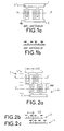
- FIG. 1b represents a sectional view, along an axis xx ′, of the structure illustrated in Figure 1a.
- this section view we can distinguish the different fingers of the two electrodes which are deposited on the surface of a piezoelectric substrate not shown. We also represented the potential of these fingers.
- a differential input transducer can be easily constructed from two transducers with non-differential inputs.
- two transducers identical to that of FIGS. 1a and 1b, are connected at series.
- the connection areas connected to earth, respective to each of the two transducers are common.
- These two transducers form respectively two acoustic channels.
- These two acoustic paths can appear as a single channel by shifting the two channels horizontally from ⁇ / 2, ⁇ being the wavelength corresponding to the central operating frequency of the transducer.
- Figures 2b and 2c respectively represent a view in section along an axis xx 'and yy', of the first and second transducers 3 and 4.
- the different potentials are indicated above each finger corresponding to the electrodes connected, via their respective connection pads, to differential inputs.
- a major drawback of such a structure is that the impedance view between the differential inputs is four times that of a structure with non-differential inputs having the same opening as that used by both routes.
- the two transducers already described in the structure illustrated in FIG. 2a are connected in parallel and not in series.
- Each of the transducers 5 and 6 is connected directly between the differential inputs V + and V-, the reference potential (ground) no longer being present.
- the symmetry of the two accesses is restored by the inversion of the polarities on the two DARTs.
- This reversal of polarity can be compensated for simply by shifting the two transducers 5 and 6 by an odd number of half wavelengths, which makes it possible to obtain a symmetrical wavefront.
- this is not compulsory and it is very easy to accept generating an asymmetric wavefront, the device and for example the reception transducer having to be designed taking this into account.
- connection to the differential inputs equivalent to the connection of the previous structure, only uses the two connection pads of two electrodes 7 and 8, each connection pad being respectively connected to one of the two differential inputs V + and V - , and by connecting the fingers 9i and 10i being interconnected so as to respect on each channel the same sequence of polarity on the different electrodes.
- a first acoustic channel is formed from the first electrode 7 connected to a first differential input V- by through its connection range.
- This electrode 7 includes a specified number of fingers of specified widths and at positions determined all along electrode 7.
- a second channel is formed at from a second electrode 8 also in the form of a comb comprising the same number of fingers as the first electrode 7, connected by through its connection range to the other differential input V +.
- a same determined number of fingers 9i and 10i belonging respectively to two electrodes 7 and 8 are intertwined with the other fingers of the electrodes 7 and 8.
- a special feature of this structure is that the number determined from fingers 9i of the first electrode 7 belongs to the second acoustic path, and that the same determined number of fingers 10i of the second electrode 8 belongs to the first acoustic channel.
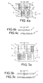
- the views in section of Figures 4b and 4c allow to understand how the different potentials are distributed on each finger, respectively for the first transducer 7 along a cutting axis xx 'and for the second transducer 8 along a cutting axis yy '.
- the transducer according to the invention exploits the fact that a wave acoustic is generated by a potential difference applied between two adjacent fingers and not by absolute potential.
- FIGS. 4b and 4c compared respectively to those of FIGS. 2b and 2c show that the potential difference between two adjacent fingers of FIGS. 4a, 4b, 4c is twice that measured between two adjacent fingers of FIGS. 2a, 2b, 2c. This is because the connection to the reference potential (ground) has been removed.
- FIG. 4a two fingers having the same polarity in the two channels are connected.
- the fingers 9i and 10i of the electrodes 7 and 8 which are interlaced with the other fingers are produced from the extension of other fingers as is the case for the first electrode, or by the extension of a first finger 11, hatched in the figure, which is added to allow connection to the potential V + of the second electrode 8.
- a second finger 12, hatched, of the first electrode 7 has also been added to the first acoustic channel to keep the same number of fingers at each of the channels. This ensures the same impedance seen between the differential inputs V + and V- and therefore ensures the symmetry of the impedances of the transducer.
- FIG. 5a it is possible to add two fingers 13i and 14i respectively at the two opposite ends of the two tracks. This allows the ends of the two tracks to be aligned while maintaining a number of identical fingers for both channels.
- the sectional views of Figures 5b and 5c allow us to understand how the different potentials are distributed on each finger, respectively for the first transducer 7 along a cutting axis xx 'and for the second transducer 8 along a cutting axis yy '.
- the offset of the two transducers 5 and 6 is not essential, it is nevertheless important because it solves a problem of connectors.
- FIGS. 6a, 6b, 6c illustrate an application of a transducer according to the invention to a differential structure of DART using sources with a period of ⁇ / 3 and fingers of width ⁇ / 6.
- the interlaced fingers 15i and 16i are not arranged directly in the extension of a preexisting finger of the electrode 7 and 8.
- these fingers 16i are attached to the end of two adjacent fingers of the same electrode 8 which are slightly extended to allow the electrical connection of the interlaced finger 16i with the potential V + .
- the two transducers 7 and 8 being, as for the structure of Figure 4a, offset by ⁇ / 2, the interlaced fingers 15i of the first electrode 7 undergo a shift of ⁇ / 2 relative to the interlaced fingers 16i of the second electrode 8.
- the interlaced fingers 15i of the first electrode 7 are located offset from the other fingers of the electrode 7 supporting them which are also extended to ensure electrical connection with potential V-.
- FIGS. 7a, 7b and 7c another structure of a transducer according to the invention is illustrated.
- Figures 8 and 9 respectively illustrate the two types of offsets allowed by a transducer according to the invention.
- the offset between the two acoustic channels is a odd multiple of ⁇ / 2 such as 3 ⁇ / 2. This can be used for get extra zeros in the transfer function of the transducer.
- the acoustic wave A (y) generated is symmetrical since the acoustic waves from both channels are in phase.
- the offset between the two acoustic channels is a even multiple of ⁇ / 2 like 0 or ⁇ for example.
- Acoustic wave A (y) generated is then asymmetric.
Landscapes
- Physics & Mathematics (AREA)
- Acoustics & Sound (AREA)
- Surface Acoustic Wave Elements And Circuit Networks Thereof (AREA)
Claims (2)
- Oberflächenschallwellenwandler, der differentiell angesteuert wird und aus einer Zweikanalstruktur gebildet ist, wobei jeder Kanal aus einem Kanalwandler (5, 6) gebildet ist, der mehrere Finger (12, 10i), (11, 9i) enthält, die mit dem einen oder dem anderen der differentiellen Eingänge (V+, V-) verbunden sind, dadurch gekennzeichnet, daß die mehreren Finger (12, 10i), (11, 9i) für jeden Kanal eine Folge von Fingerbreiten, die bis auf eine Verschiebung um ein Vielfaches von λ/2 völlig gleich sind, und eine Folge von elektrischen Polaritäten, die zwischen den beiden Kanälen bis auf eine Verschiebung um ein Vielfaches von λ/2 gleich oder entgegengesetzt sind, bilden, daß jeder Kanalwandler (5, 6) einen einzigen Verbindungsbereich (7, 8) enthält, der mit einem der differentiellen Eingänge (V+, V-) verbunden ist, und daß für einen gegebenen Kanal die Finger (10i, 9i) dieses Kanals, die die entgegengesetzte Polarität des Verbindungsbereichs (7, 8) dieses Kanals besitzen, mit dem Verbindungsbereich (7, 8) des anderen Kanals über Finger (11, 12), die an diesen letzten Kanal angefügt sind, verbunden sind.
- Wandler nach Anspruch 1, dadurch gekennzeichnet, daß der Wandler (5, 6) jedes Kanals vom Typ DART ist.
Applications Claiming Priority (4)
| Application Number | Priority Date | Filing Date | Title |
|---|---|---|---|
| FR9513132A FR2740908B1 (fr) | 1995-11-07 | 1995-11-07 | Transducteur a ondes acoustiques de surface attaque en differentiel |
| FR9513132 | 1995-11-07 | ||
| CA002236764A CA2236764C (en) | 1995-11-07 | 1996-10-31 | Surface acoustic wave transducer driven in differential mode |
| PCT/FR1996/001717 WO1997017756A1 (fr) | 1995-11-07 | 1996-10-31 | Transducteur a ondes acoustiques de surface attaque en differentiel |
Publications (2)
| Publication Number | Publication Date |
|---|---|
| EP0862813A1 EP0862813A1 (de) | 1998-09-09 |
| EP0862813B1 true EP0862813B1 (de) | 1999-11-24 |
Family
ID=25680185
Family Applications (1)
| Application Number | Title | Priority Date | Filing Date |
|---|---|---|---|
| EP96937377A Expired - Lifetime EP0862813B1 (de) | 1995-11-07 | 1996-10-31 | Differenzbetriebener wandler für akustische oberflächenwellen |
Country Status (5)
| Country | Link |
|---|---|
| US (1) | US6011344A (de) |
| EP (1) | EP0862813B1 (de) |
| DE (1) | DE69605321T2 (de) |
| FR (1) | FR2740908B1 (de) |
| WO (1) | WO1997017756A1 (de) |
Families Citing this family (8)
| Publication number | Priority date | Publication date | Assignee | Title |
|---|---|---|---|---|
| FR2774826B1 (fr) | 1998-02-06 | 2000-05-05 | Thomson Csf | Filtre a resonateurs a ondes acoustiques de surface |
| DE19907640A1 (de) * | 1998-03-25 | 1999-10-07 | Dresden Ev Inst Festkoerper | Akustisches Oberflächenwellenbauelement |
| WO2002043462A2 (en) * | 2000-11-29 | 2002-06-06 | Soliton Holdings Corp. | Saw wave-guides |
| JP4079658B2 (ja) * | 2002-03-05 | 2008-04-23 | 株式会社リコー | 2値化ウォブル信号を生成する回路、ライトクロック生成回路、2値化ウォブル信号を生成する方法、ライトクロック生成方法及び光ディスク装置 |
| FR2837636B1 (fr) * | 2002-03-19 | 2004-09-24 | Thales Sa | Dispositif a ondes acoustiques d'interface en tantalate de lithium |
| FR2864618B1 (fr) * | 2003-12-24 | 2006-03-03 | Temex Sa | Capteur de temperature ou de temperature et de pression interrogeable a distance |
| DE102005045638B4 (de) * | 2005-09-23 | 2017-02-02 | Epcos Ag | Mit Oberflächenwellen arbeitender Wandler |
| JP6441590B2 (ja) * | 2014-05-23 | 2018-12-19 | 太陽誘電株式会社 | 弾性波デバイス |
Family Cites Families (9)
| Publication number | Priority date | Publication date | Assignee | Title |
|---|---|---|---|---|
| FR2319245A1 (fr) * | 1975-07-24 | 1977-02-18 | Thomson Csf | Transducteur perfectionne pour filtre a ondes de surface a fonction de transfert asymetrique et filtre comportant un tel transducteur |
| US4081769A (en) * | 1976-09-13 | 1978-03-28 | Texas Instruments Incorporated | Acoustic surface wave resonator with suppressed direct coupled response |
| GB1554366A (en) * | 1977-02-04 | 1979-10-17 | Philips Electronic Associated | Acoustic surface wave devices |
| US4405874A (en) * | 1982-03-01 | 1983-09-20 | Northern Telecom Limited | Surface acoustic wave (saw) devices having series-connected inter-digital transducers |
| US4491757A (en) * | 1983-05-03 | 1985-01-01 | R F Monolithics, Inc. | Transversely weighted surface acoustic wave device |
| FR2628265B1 (fr) * | 1987-03-06 | 1990-12-21 | Thomson Csf | Antenne directive a transducteurs multiples notamment pour sonar |
| FR2682833B1 (fr) * | 1991-10-18 | 1993-12-03 | Thomson Csf | Filtre a ondes de surface et a trajet acoustique replie. |
| US5703427A (en) * | 1993-03-19 | 1997-12-30 | Thomson-Csf | Surface-wave distributed acoustic reflection transducer and filter including such a transducer |
| GB2289181B (en) * | 1994-04-25 | 1998-08-12 | Advanced Saw Prod Sa | Saw filter |
-
1995
- 1995-11-07 FR FR9513132A patent/FR2740908B1/fr not_active Expired - Fee Related
-
1996
- 1996-10-31 WO PCT/FR1996/001717 patent/WO1997017756A1/fr not_active Ceased
- 1996-10-31 DE DE69605321T patent/DE69605321T2/de not_active Expired - Lifetime
- 1996-10-31 EP EP96937377A patent/EP0862813B1/de not_active Expired - Lifetime
- 1996-10-31 US US09/068,122 patent/US6011344A/en not_active Expired - Lifetime
Also Published As
| Publication number | Publication date |
|---|---|
| WO1997017756A1 (fr) | 1997-05-15 |
| EP0862813A1 (de) | 1998-09-09 |
| DE69605321D1 (de) | 1999-12-30 |
| DE69605321T2 (de) | 2000-05-31 |
| FR2740908B1 (fr) | 1997-11-28 |
| US6011344A (en) | 2000-01-04 |
| FR2740908A1 (fr) | 1997-05-09 |
Similar Documents
| Publication | Publication Date | Title |
|---|---|---|
| EP0608249B2 (de) | Oberflächenwellenfilter mit einem gefalteten akustischen pfad | |
| EP0872954B1 (de) | Akustische Oberflächenwellenanordnung mit Nahfeldkopplung und differentiellen Ein- und Ausgängen | |
| EP1053593B1 (de) | Resonatorfilter mit akustischen oberflächenwellen | |
| EP0862813B1 (de) | Differenzbetriebener wandler für akustische oberflächenwellen | |
| EP0513085B2 (de) | Akustische oberflächenwellenfilter | |
| EP0852846B1 (de) | Oberflächenfilter unter verwendung der kopplung zwischen drei akustischen spuren | |
| EP3996275A2 (de) | Elektromechanische vorrichtung mit einstellbarer resonanzfrequenz | |
| EP0660981B1 (de) | Wandler für unidirektionale Weller | |
| EP1368895A1 (de) | Oberflächenwellenfilter | |
| FR2776863A1 (fr) | Composant acoustique a ondes de surface | |
| FR2468255A1 (fr) | Dispositifs a ondes acoustiques de surface et systemes comportant de tels dispositifs | |
| EP0369835B1 (de) | Wandler für ein akustisches Oberflächenwellen-Filter | |
| EP0424240B1 (de) | Richtwandler für Oberflächenwellen | |
| FR2782568A1 (fr) | Filtre acoustique a deux canaux differents a compensation de rejection | |
| FR2590089A1 (fr) | Convolutionnement a codage par dephasage differentiel | |
| FR2818051A1 (fr) | Flitres a ondes acoustiques de surface a symetrie optimisee | |
| WO1995014332A1 (fr) | Filtre a ondes de surface a trajet acoustique replie | |
| EP0646296B1 (de) | Wandler für Oberflächenwellen mit verteilter akustischer Reflektion und Filter mit solch einem Wandler | |
| WO2004042862A1 (fr) | Filtre passe-bande hyperfrequences a large bande | |
| EP0576340A1 (de) | Oberflächenwellenfilter mit reflektierenden Gittern | |
| FR2618609A1 (fr) | Ligne hyperfrequence du type triplaque comportant une connexion de masse | |
| WO2004042863A1 (fr) | Dispositif separateur de bandes hyperfrequences a large bande |
Legal Events
| Date | Code | Title | Description |
|---|---|---|---|
| PUAI | Public reference made under article 153(3) epc to a published international application that has entered the european phase |
Free format text: ORIGINAL CODE: 0009012 |
|
| 17P | Request for examination filed |
Effective date: 19980504 |
|
| AK | Designated contracting states |
Kind code of ref document: A1 Designated state(s): CH DE FI FR GB IT LI SE |
|
| GRAG | Despatch of communication of intention to grant |
Free format text: ORIGINAL CODE: EPIDOS AGRA |
|
| 17Q | First examination report despatched |
Effective date: 19981230 |
|
| GRAG | Despatch of communication of intention to grant |
Free format text: ORIGINAL CODE: EPIDOS AGRA |
|
| GRAH | Despatch of communication of intention to grant a patent |
Free format text: ORIGINAL CODE: EPIDOS IGRA |
|
| GRAH | Despatch of communication of intention to grant a patent |
Free format text: ORIGINAL CODE: EPIDOS IGRA |
|
| GRAA | (expected) grant |
Free format text: ORIGINAL CODE: 0009210 |
|
| AK | Designated contracting states |
Kind code of ref document: B1 Designated state(s): CH DE FI FR GB IT LI SE |
|
| REG | Reference to a national code |
Ref country code: CH Ref legal event code: EP |
|
| REF | Corresponds to: |
Ref document number: 69605321 Country of ref document: DE Date of ref document: 19991230 |
|
| GBT | Gb: translation of ep patent filed (gb section 77(6)(a)/1977) |
Effective date: 20000113 |
|
| ITF | It: translation for a ep patent filed | ||
| PLBE | No opposition filed within time limit |
Free format text: ORIGINAL CODE: 0009261 |
|
| STAA | Information on the status of an ep patent application or granted ep patent |
Free format text: STATUS: NO OPPOSITION FILED WITHIN TIME LIMIT |
|
| PG25 | Lapsed in a contracting state [announced via postgrant information from national office to epo] |
Ref country code: LI Free format text: LAPSE BECAUSE OF NON-PAYMENT OF DUE FEES Effective date: 20001031 Ref country code: CH Free format text: LAPSE BECAUSE OF NON-PAYMENT OF DUE FEES Effective date: 20001031 |
|
| 26N | No opposition filed | ||
| REG | Reference to a national code |
Ref country code: CH Ref legal event code: PL |
|
| REG | Reference to a national code |
Ref country code: GB Ref legal event code: IF02 |
|
| REG | Reference to a national code |
Ref country code: FR Ref legal event code: CD |
|
| PGFP | Annual fee paid to national office [announced via postgrant information from national office to epo] |
Ref country code: FI Payment date: 20081030 Year of fee payment: 13 |
|
| PGFP | Annual fee paid to national office [announced via postgrant information from national office to epo] |
Ref country code: SE Payment date: 20081029 Year of fee payment: 13 Ref country code: IT Payment date: 20081029 Year of fee payment: 13 |
|
| PGFP | Annual fee paid to national office [announced via postgrant information from national office to epo] |
Ref country code: FR Payment date: 20081018 Year of fee payment: 13 |
|
| PGFP | Annual fee paid to national office [announced via postgrant information from national office to epo] |
Ref country code: GB Payment date: 20081029 Year of fee payment: 13 |
|
| EUG | Se: european patent has lapsed | ||
| REG | Reference to a national code |
Ref country code: FR Ref legal event code: ST Effective date: 20100630 |
|
| PG25 | Lapsed in a contracting state [announced via postgrant information from national office to epo] |
Ref country code: FR Free format text: LAPSE BECAUSE OF NON-PAYMENT OF DUE FEES Effective date: 20091102 |
|
| PG25 | Lapsed in a contracting state [announced via postgrant information from national office to epo] |
Ref country code: FI Free format text: LAPSE BECAUSE OF NON-PAYMENT OF DUE FEES Effective date: 20091031 |
|
| PG25 | Lapsed in a contracting state [announced via postgrant information from national office to epo] |
Ref country code: GB Free format text: LAPSE BECAUSE OF NON-PAYMENT OF DUE FEES Effective date: 20091031 |
|
| PG25 | Lapsed in a contracting state [announced via postgrant information from national office to epo] |
Ref country code: IT Free format text: LAPSE BECAUSE OF NON-PAYMENT OF DUE FEES Effective date: 20091031 |
|
| PG25 | Lapsed in a contracting state [announced via postgrant information from national office to epo] |
Ref country code: SE Free format text: LAPSE BECAUSE OF NON-PAYMENT OF DUE FEES Effective date: 20091101 |
|
| PGFP | Annual fee paid to national office [announced via postgrant information from national office to epo] |
Ref country code: DE Payment date: 20151022 Year of fee payment: 20 |
|
| REG | Reference to a national code |
Ref country code: DE Ref legal event code: R071 Ref document number: 69605321 Country of ref document: DE |