EP0862881B1 - Système de montage - Google Patents
Système de montage Download PDFInfo
- Publication number
- EP0862881B1 EP0862881B1 EP19980301279 EP98301279A EP0862881B1 EP 0862881 B1 EP0862881 B1 EP 0862881B1 EP 19980301279 EP19980301279 EP 19980301279 EP 98301279 A EP98301279 A EP 98301279A EP 0862881 B1 EP0862881 B1 EP 0862881B1
- Authority
- EP
- European Patent Office
- Prior art keywords
- body portion
- mounting
- curved surface
- support member
- bracket
- Prior art date
- Legal status (The legal status is an assumption and is not a legal conclusion. Google has not performed a legal analysis and makes no representation as to the accuracy of the status listed.)
- Expired - Lifetime
Links
Images


Classifications
-
- E—FIXED CONSTRUCTIONS
- E06—DOORS, WINDOWS, SHUTTERS, OR ROLLER BLINDS IN GENERAL; LADDERS
- E06B—FIXED OR MOVABLE CLOSURES FOR OPENINGS IN BUILDINGS, VEHICLES, FENCES OR LIKE ENCLOSURES IN GENERAL, e.g. DOORS, WINDOWS, BLINDS, GATES
- E06B9/00—Screening or protective devices for wall or similar openings, with or without operating or securing mechanisms; Closures of similar construction
- E06B9/24—Screens or other constructions affording protection against light, especially against sunshine; Similar screens for privacy or appearance; Slat blinds
- E06B9/26—Lamellar or like blinds, e.g. venetian blinds
- E06B9/28—Lamellar or like blinds, e.g. venetian blinds with horizontal lamellae, e.g. non-liftable
- E06B9/30—Lamellar or like blinds, e.g. venetian blinds with horizontal lamellae, e.g. non-liftable liftable
- E06B9/32—Operating, guiding, or securing devices therefor
- E06B9/323—Structure or support of upper box
-
- A—HUMAN NECESSITIES
- A47—FURNITURE; DOMESTIC ARTICLES OR APPLIANCES; COFFEE MILLS; SPICE MILLS; SUCTION CLEANERS IN GENERAL
- A47H—FURNISHINGS FOR WINDOWS OR DOORS
- A47H1/00—Curtain suspension devices
- A47H1/10—Means for mounting curtain rods or rails
- A47H1/14—Brackets for supporting rods or rails
- A47H1/144—Brackets for supporting rods or rails for supporting rails
Definitions
- This invention relates to a mounting system for a window covering product, such as a blind or shade arrangement, particularly to affix such a product to a ceiling or wall or to an architectural opening, such as a door or window frame.
- One form of mounting system includes a mounting bracket as disclosed in GB-B-2,267,526.
- the bracket comprises a main body portion with a mounting aperture extending through it, a first inturned flange on one edge of the main body portion, and a second inturned flange on the opposite edge of the main body portion.
- the inturned flanges can be attached to a rail of a window covering product, and a fixing means, such as a mounting screw or nail, can pass through the mounting aperture to affix the bracket to a ceiling, wall or door or window frame.
- the rail which is usually part of a window covering product, could be affixed to the mounting bracket to support blinds or shades or even curtains.
- a fixing means such as an ordinary screw
- the building structure preferably had to have a fixation surface perpendicular to the desired orientation of the window covering product and be capable of accommodating fixation of the main body of the mounting bracket. If the building structure had a sloping fixation surface, such as for example exists with skylight frames, one could have provided one or more wedges between the fixation surface and the main body portion of the bracket, to provide the desired orientation for the window covering product.
- a disadvantage of the known bracket has been that the fixation surface of the building structure has preferably had to be perpendicular to the desired orientation of the window covering product, to enable uncomplicated fixation of the mounting bracket.
- a mounting system for mounting the headrail or bottom rail of a window covering product to a fixation surface including a mounting bracket comprising a body portion and a mounting aperture in said body portion, opposed edges of said body portion being adapted to engage said rail, fixing means engaged in said mounting aperture and adapted to mount the bracket on a building structure, characterised in that said mounting aperture is in or adjacent to a convex curved surface of either said body portion or of said fixing means, thereby enabling said body portion and the rail supported thereby to be adjusted in position and at an angle determined by the position of said fixing means or body portion, respectively relative to said curved surface.
- the invention also contemplates a mounting system for affixing the headrail or bottom rail of a window covering product to a fixation surface of a building structure
- the mounting bracket comprises: a main body portion having a first mounting aperture therein and opposite edges of the main body portion are adapted to engage the rail; and fixing means connected to the first mounting aperture for affixing the bracket to the fixation surface of the building structure, characterized by:
- Such a bracket allows easy fixation of a rail of a window covering product to a sloping fixation surface of a building structure.
- the convex curved surface, containing the elongate slot is provided on the main body portion of the bracket; the first mounting aperture is in the elongate slot; the fixing means extends through the elongate slot and engages the fixation surface, so that the main body portion is convex relative to the fixation surface; and preferably, the elongate slot extends transversely to the opposite edges of the main body portion (which engage the rail of the window covering product).
- the main body portion of this bracket is formed of arcuately curved sheet material whereby one face of the main body portion is its convex curved surface. Such a bracket can be easily adjusted to a desired orientation relative to a sloping fixation surface of a building structure.
- the fixing means comprises:
- the support member is tubular, and the second mounting means comprises a second mounting aperture for the passage of a conventional mounting screw.
- the circumferentially elongate slot in the support member is also enlarged, opposite the second mounting aperture, so that a screw driver can readily access the mounting screw in the second mounting aperture.
- the main body portion is also advantageously made of a resilient material and one edge is provided with an outwardly extending release member, enabling the main body portion to be flexed to disengage the one edge from the rail of the window covering product.
- FIG. 1 shows a mounting bracket 10a, known from the prior art.
- the bracket 10a has a substantially flat, main or central body portion 20a, having a mounting aperture 22a extending through it.
- a first edge 24a and a second edge 26a, on opposite sides of the main body portion 20a, have respectively a first inturned flange 30a and a second inturned flange 40a.
- the mounting aperture 22a extends transversely to the edges 24a and 26a and can accommodate a fixing means, such as a conventional mounting screw, to affix the main body portion 20a to a fixation surface on a building structure, such as a ceiling or a wall or an architectural opening such as a door or window frame.
- the inturned flanges 30a and 40a can be used to affix a rail (e.g., a head rail of a window covering product) to the bracket 10a, with the flanges extending in the same direction as the rail.
- a rail e.g.,
- the second inturned flange 40a is provided with an outturned member 42a.
- Such resilient material allows the rail to be clipped or slid onto the inturned flanges 30a and 40a of the bracket 10a, so that the outturned member 42a can thereafter be used to facilitate the separation of the second inturned flange 40a from the rail.
- a building structure in order to obtain a desired orientation and proper operation of a window covering product, a building structure preferably had to have a fixation surface perpendicular to the desired orientation of the window covering product and be capable of accommodating fixation of the main body portion 20a of the known mounting bracket 10a. If the building structure had a sloping surface, as for example existed with skylight frames, one might have to apply one or more wedges between the main body portion 20a of the bracket and the fixation surface to provide the desired orientation to the window covering product, which would require a complex and complicated installation.
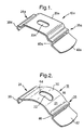
- FIGs 2-4 show one embodiment of a mounting bracket 10 in accordance with this invention.
- the main body portion 20 of the mounting bracket 10 in accordance with the invention is formed with a profile that is a convex curve as shown in Figures 3 and 4.
- the upper surface 21 of the main body portion 20, as shown in Figure 2 is a convex curved surface.
- This convex curved surface 21 of the main body portion 20 is intended to be convex relative to the fixation surface 70, to be affixed to the bracket 10 (as shown in Figure 4), but concave relative to the rail to be fixed to the flanges 30,40 of the main body portion 20 (as also shown in Figure 4).
- This convex curved surface 21 of the main body portion 20 is provided with a mounting aperture 22 that is a circumferentially elongate slot, extending through the main body portion transversely of the first and second edges 24,26 on opposite sides of the main body portion 20.
- Inturned flanges 30 and 40, on the opposite sides of the main body portion 20, enable the bracket 10 to be affixed to a rail of a window covering, with the flanges extending in the lengthwise direction of the rail.
- the lower surface 27 of the main body portion 20 is preferably parallel to the upper surface 21 and therefore is also a concave curved surface. However, it is not necessary that the lower surface 27 be parallel to the upper surface 21 or be also a convex curved surface.
- a desired orientation of a window covering product can be obtained by moving the mounting bracket 10 on a fixation means 52 (in Figure 4), inserted through the circumferentially elongate, mounting aperture 22, along the convex curved surface 21 of the main body portion 20 and then fixing the bracket 10 and its inturned flanges 30 and 40 at the desired orientation with the fixing means.
- the bracket 10 and its main body portion 20 are preferably formed of a sheet material, e.g., metal, which is arcuately curved along a radius 60 having a centre point 62, to define the convex curved surface 21 as shown in Figures 3 and 4.
- the circumferentially elongate, mounting aperture 22 has ends 64,66, which are equally spaced from a centre line 68 and determine a maximum angle between the main body portion 20 and a given fixation surface of a building structure.
- the bracket 10 has a smooth convex curve in its main body portion 20, any substantially curved surface will work at least to some extent.
- the main body portion 20 can have a plurality of rectangular facets arranged perpendicularly to the circumferentially elongate, mounting aperture 22, these collectively defining a convex curved surface.
- Such an embodiment provides certain predetermined orientations of the mounting bracket and assures most optimal fixation.
- the mounting bracket 10 does not need to have a symmetrical shape, nor does the mounting aperture 22 need to have a central location in the main body 20.
- Figure 4 shows a fixation surface 70 of a building structure with the mounting bracket 10 of Figures 2 and 3 fixed in place.
- the bracket 10 holds a rail 50 and is provided with a fixing means, here a screw 52.
- the rail 50 which can be part of any window covering product, is only schematically shown -- without any operating means or shade or blind body.
- the fixation surface shown is a sloped ceiling 70 with a window arrangement 80, having a frame 82 accommodating a pane 84, and a pane lath 86.
- the mounting bracket 10 is fixed with the screw 52 through the mounting slot 22 into the ceiling 70, so that a window covering product can be suspended parallel to the pane 84 on the ceiling 70 that is sloped in a direction transverse of the length of the rail of the window covering product.
- the main body portion 20 and its circumferentially elongate, mounting aperture 22 can be curved in other directions.
- their convex curvature can be parallel to, rather than transverse of, the inturned flanges 30 and 40, on the opposite sides of the main body portion 20. This would allow the bracket 10 to be affixed to a fixation surface 70 that is uneven or sloped in the lengthwise, rather than the transverse, direction of the rail of the window covering, to be attached to the inturned flanges 30 and 40 of the bracket 10.
- the bracket 10 can be used to affix other parts of a window covering product, such as a bottom rail.
- a window covering product may have both a head rail and a bottom rail, which can be both easily affixed with the bracket 10, even to frames having sloping surfaces.
- Figures 5 -7 show an alternative mounting bracket 110 of this invention comprising an elongate hollow support member 111 and a main body portion 120.
- the support member 111 preferably is generally tubular and therefore has a profile with a convex curved outer surface 112 on a first circumferential side 113, adjacent to the main body portion 120, as shown in Figure 7.
- this convex curved surface 112 of the support member 111 is intended to be convex relative to the main body portion 120, to be affixed to the rail (not shown), but concave relative to the fixation surface 170 (not shown), to be fixed to an opposite second circumferential side 115 of the support member 111.
- the convex curved surface 112 of the support member 111 is intended to be convex relative to the main body portion 120, to be affixed to the rail (not shown), but concave relative to the fixation surface 170 (not shown), to be fixed to an opposite second circumferential side 115 of the support member 111.
- the convex curved surface 112 of the support member 111 has a circumferentially elongate slot 114 extending through it, adjacent to the main body portion 120.
- the elongate slot 114 can extend circumferentially around the support member 111 for up to about 180°.
- the inner surface 117 of the support member 111 is preferably parallel to the outer surface 112 and therefore is also a concave curved surface. However, it is not necessary that the inner surface 117 be parallel to the outer surface 112 or be also a convex curved surface.
- the second circumferential side 115 of the support member 111 is mounted on a fixation surface 170 of a building structure by means of a conventional mounting screw 116.
- the mounting screw 116 passes through a first mounting aperture 118 in the second side 115 of the support member 111 and into the fixation surface 170.
- the first and second sides 113 and 115 of the support member 111 are on substantially opposite circumferential sides of the support member 111.
- the main body portion 120 of the mounting bracket 110 preferably is generally similar to the main body portion 20a of the known bracket 10a of Figure 1 but can also be like the main body portion 20 of the bracket 10 of Figures 2-4.
- a second mounting aperture 122 which can be circular or elongate, extends through the main body portion 120.
- the inturned flanges 130 and 140 are adapted to be affixed to a rail of a window covering in the lengthwise direction of the rail, so that the rail extends in a direction transverse of the slope of the fixation surface 170.
- a conventional fixing bolt 152 Passing through the second mounting aperture 122 and through the elongate slot 114 of the support member 111, on its first circumferential side 113, is a conventional fixing bolt 152, threaded into a nut 154 within the support member.
- the nut 154 has a female screw thread cooperating with the thread of the bolt 152.
- the nut 154 preferably has a rectangular shape or at least a pair of flats on opposite sides and is dimensioned to fit closely within the support member 111, as shown in Figure 7, so that the nut 154 will not rotate when the bolt 152 is threaded through it.
- the position of the bracket 110 can be adjusted along the circumferential convex outer surface 112 of the support member 111 by adjusting the position of the bolt 152 within the elongate slot 114.
- the bolt 152 can thereafter be tightened again in any adjusted position to secure the main body portion 120 to the support member 111 and thereby to the fixation surface 170 at a desired relative angular orientation.
- a screw driver can readily access the mounting screw 116 in the first mounting aperture 118, through the enlarged area 119 in the slot 114, to affix the support member 120 of the bracket 110 to a fixation surface 170 of a building structure.
- the outer surface of the support member 111 of the bracket 110 can also have a plurality of rectangular facets collectively defining the convex curved outer surface 112 on its first circumferential side 113.
- the main body portion 120 can also have its inturned flanges 130 and 140 extend in the direction of the elongate slot 114 in the support member 111. This would allow the bracket 110 and the rail of a window covering, mounted on the bracket, to be affixed to a fixation surface 170 that is uneven or sloped in the lengthwise, rather than the transverse, direction of the rail.
Landscapes
- Engineering & Computer Science (AREA)
- Structural Engineering (AREA)
- Architecture (AREA)
- Civil Engineering (AREA)
- Curtains And Furnishings For Windows Or Doors (AREA)
Claims (10)
- Système de fixation pour fixer le rail de guidage ou le rail inférieur d'un produit de couverture de fenêtre à une surface de fixation comportant un crochet de montage (10) comprenant une partie de corps (20) et une ouverture de fixation (22) dans ladite partie de corps, les bords opposés (24, 26) de ladite partie de corps étant adaptés pour engager ledit rail, des moyens de fixation engagés dans ladite ouverture de fixation (22) et adaptés pour monter le crochet sur une structure d'immeuble, caractérisé en ce que ladite ouverture de fixation se trouve dans, ou adjacente à une surface recourbée convexe (21, 112), soit de ladite partie de corps, soit desdits moyens de fixation, permettant de ce fait à ladite partie de corps et au rail ainsi supporté d'être ajustés en place et suivant un angle déterminé par la position desdits moyens de fixation ou de ladite partie de corps, respectivement par rapport à ladite surface recourbée.
- Système de fixation selon la revendication 1, caractérisé en ce que ladite surface recourbée (21) est formée sur ladite partie de corps (20), et en ce que ladite ouverture de fixation (22) se présente sous la forme d'une fente en longueur s'étendant sur 1 périphérie de ladite surface recourbée.
- Système de fixation selon la revendication 2, caractérisé en ce que ladite fente allongée (22) s'étend transversalement aux dits bords.
- Système de fixation selon la revendication 2 ou 3, caractérisé en ce que la partie de corps (20) est formée d'un matériau en tôle recourbée en forme d'arc pour former ladite surface convexe (21) sur l'une de ses faces.
- Système de fixation selon la revendication 1, caractérisé en ce que lesdits moyens de fixation comprennent un élément de support (111) formé avec ladite surface recourbée convexe (112), des moyens (116) pour fixer ledit élément de support sur une structure d'immeuble, une fente de forme allongée (114) formée dans ladite surface recourbée convexe (112) dudit élément de support, et un boulon (152) passant à travers ladite ouverture de fixation dans ladite partie de corps, à travers la fente de forme allongée dans l'élément de support et s'engageant avec un écrou (154) placé à l'intérieur de l'élément de support.
- Système de fixation selon la revendication 5, caractérisé en ce que l'élément de support se présente sous la forme d'un élément tubulaire.
- Système de fixation selon la revendication 6, caractérisé en ce que le tube de support possède, opposé à la fente de forme allongée (114), un trou (118) destiné au passage de la vis de fixation.
- Système de fixation selon la revendication 7, caractérisé en ce que la fente de forme allongée (114) du tube de support est prévue avec un agrandissement (119), opposé au trou, destiné à un tournevis pour donner accès à la vis de fixation (116).
- Système de fixation selon l'une quelconque des revendications précédentes, caractérisé en ce que la partie de corps est constituée d'un matériau élastique et en ce que l'un des bords est pourvu d'un élément de libération s'étendant vers l'extérieur, permettant à la partie de corps d'être pliée pour désengager ce bord du rail.
- Système de fixation selon l'une quelconque des revendications précédentes, caractérisé en ce que la partie de corps est dotée d'une pluralité de facettes rectangulaires agencées perpendiculairement à la fente de forme allongée, les facettes constituant collectivement ladite surface recourbée convexe.
Priority Applications (1)
| Application Number | Priority Date | Filing Date | Title |
|---|---|---|---|
| EP19980301279 EP0862881B1 (fr) | 1997-02-19 | 1998-02-18 | Système de montage |
Applications Claiming Priority (5)
| Application Number | Priority Date | Filing Date | Title |
|---|---|---|---|
| EP97200473 | 1997-02-19 | ||
| EP97200473 | 1997-02-19 | ||
| EP97305177 | 1997-07-14 | ||
| EP97305177 | 1997-07-14 | ||
| EP19980301279 EP0862881B1 (fr) | 1997-02-19 | 1998-02-18 | Système de montage |
Publications (3)
| Publication Number | Publication Date |
|---|---|
| EP0862881A2 EP0862881A2 (fr) | 1998-09-09 |
| EP0862881A3 EP0862881A3 (fr) | 2001-12-12 |
| EP0862881B1 true EP0862881B1 (fr) | 2004-08-18 |
Family
ID=27238401
Family Applications (1)
| Application Number | Title | Priority Date | Filing Date |
|---|---|---|---|
| EP19980301279 Expired - Lifetime EP0862881B1 (fr) | 1997-02-19 | 1998-02-18 | Système de montage |
Country Status (1)
| Country | Link |
|---|---|
| EP (1) | EP0862881B1 (fr) |
Cited By (1)
| Publication number | Priority date | Publication date | Assignee | Title |
|---|---|---|---|---|
| DE102005062995B3 (de) * | 2005-12-30 | 2007-05-16 | Warema Kunststofftechnik Und M | Befestigungssystem für Sonnenschutzanlagen |
Families Citing this family (4)
| Publication number | Priority date | Publication date | Assignee | Title |
|---|---|---|---|---|
| GB2334994B (en) * | 1997-08-27 | 2001-12-12 | Simon Gregory Derrek Moore | An adjustable bracket |
| AU741868B2 (en) | 1998-01-14 | 2001-12-13 | Hunter Douglas International N.V. | Support structure for an architectural covering |
| EP1512827A3 (fr) | 2003-09-03 | 2007-04-11 | Hunter Douglas Industries B.V. | Support |
| DE102005029066B4 (de) * | 2004-07-14 | 2015-09-03 | Warema Kunststofftechnik Und Maschinenbau Gmbh | Montageelement |
Family Cites Families (1)
| Publication number | Priority date | Publication date | Assignee | Title |
|---|---|---|---|---|
| GB2267526B (en) * | 1992-05-09 | 1995-11-22 | * Eclipse Blinds Limited | Bracket means |
-
1998
- 1998-02-18 EP EP19980301279 patent/EP0862881B1/fr not_active Expired - Lifetime
Cited By (1)
| Publication number | Priority date | Publication date | Assignee | Title |
|---|---|---|---|---|
| DE102005062995B3 (de) * | 2005-12-30 | 2007-05-16 | Warema Kunststofftechnik Und M | Befestigungssystem für Sonnenschutzanlagen |
Also Published As
| Publication number | Publication date |
|---|---|
| EP0862881A3 (fr) | 2001-12-12 |
| EP0862881A2 (fr) | 1998-09-09 |
Similar Documents
| Publication | Publication Date | Title |
|---|---|---|
| US6039295A (en) | Mounting system | |
| AU745402C (en) | Supporting means for a screening device | |
| CA2277399C (fr) | Ailette d'installation rotative pour produit de fenestrage | |
| EP0484178B1 (fr) | Rail de support pour porte ou paroi de séparation en verre | |
| US4570399A (en) | Panel lite insert system | |
| EP1114899A2 (fr) | Composantes pour agencements de toiture | |
| CN113727631B (zh) | 窗帘杆悬挂系统和组件 | |
| US4222156A (en) | Holder for supporting a valance at a venetian blind head | |
| US6935078B1 (en) | Anchor fastener clip | |
| EP0862881A2 (fr) | Système de montage | |
| US6659154B2 (en) | Valance with adjustable mounting features | |
| US10094168B2 (en) | Method and fastening element for installing a sunshade in a glazing part | |
| EP1308597B1 (fr) | Moyen de support pour des lamelles | |
| EP3862527B1 (fr) | Pare-soleil | |
| US20070284065A1 (en) | Mounting brackets for hanging blinds and similar structures | |
| EP0491010B1 (fr) | Procede de jonction de deux elements de structure a l'aide d'un dispositif de fixation reglable, et chassis utilise dans ledit procede | |
| JPH06229096A (ja) | キャリア組立て体 | |
| EP3333353B1 (fr) | Rail latéral pour un revêtement architectural | |
| EP0651105A2 (fr) | Vitrage structurel à montage rapide | |
| US20190162024A1 (en) | Roller blind end bracket with fascia support | |
| US20060000560A1 (en) | Apparatus and method for removably attaching window treatments | |
| US20040182592A1 (en) | Electrical box hanger | |
| JP7064756B2 (ja) | サッシ枠に対する軒端設備類の取付機構 | |
| US20150059993A1 (en) | Window treatment mounting system | |
| US3981525A (en) | Security apparatus for louver windows and doors |
Legal Events
| Date | Code | Title | Description |
|---|---|---|---|
| PUAI | Public reference made under article 153(3) epc to a published international application that has entered the european phase |
Free format text: ORIGINAL CODE: 0009012 |
|
| AK | Designated contracting states |
Kind code of ref document: A2 Designated state(s): AT BE CH DE DK ES FI FR GB GR IE IT LI LU MC NL PT SE Kind code of ref document: A2 Designated state(s): DE FR GB NL |
|
| AX | Request for extension of the european patent |
Free format text: AL;LT;LV;MK;RO;SI |
|
| PUAL | Search report despatched |
Free format text: ORIGINAL CODE: 0009013 |
|
| AK | Designated contracting states |
Kind code of ref document: A3 Designated state(s): AT BE CH DE DK ES FI FR GB GR IE IT LI LU MC NL PT SE |
|
| AX | Request for extension of the european patent |
Free format text: AL;LT;LV;MK;RO;SI |
|
| RIC1 | Information provided on ipc code assigned before grant |
Free format text: 7A 47H 1/144 A, 7E 06B 9/323 B, 7A 47H 1/13 B, 7E 06B 9/266 B |
|
| 17P | Request for examination filed |
Effective date: 20020128 |
|
| AKX | Designation fees paid |
Free format text: DE FR GB NL |
|
| GRAP | Despatch of communication of intention to grant a patent |
Free format text: ORIGINAL CODE: EPIDOSNIGR1 |
|
| GRAS | Grant fee paid |
Free format text: ORIGINAL CODE: EPIDOSNIGR3 |
|
| GRAA | (expected) grant |
Free format text: ORIGINAL CODE: 0009210 |
|
| AK | Designated contracting states |
Kind code of ref document: B1 Designated state(s): DE FR GB NL |
|
| REG | Reference to a national code |
Ref country code: GB Ref legal event code: FG4D |
|
| REG | Reference to a national code |
Ref country code: IE Ref legal event code: FG4D |
|
| REF | Corresponds to: |
Ref document number: 69825647 Country of ref document: DE Date of ref document: 20040923 Kind code of ref document: P |
|
| PLBE | No opposition filed within time limit |
Free format text: ORIGINAL CODE: 0009261 |
|
| STAA | Information on the status of an ep patent application or granted ep patent |
Free format text: STATUS: NO OPPOSITION FILED WITHIN TIME LIMIT |
|
| ET | Fr: translation filed | ||
| 26N | No opposition filed |
Effective date: 20050519 |
|
| PGFP | Annual fee paid to national office [announced via postgrant information from national office to epo] |
Ref country code: FR Payment date: 20110218 Year of fee payment: 14 Ref country code: NL Payment date: 20110216 Year of fee payment: 14 Ref country code: DE Payment date: 20110216 Year of fee payment: 14 |
|
| PGFP | Annual fee paid to national office [announced via postgrant information from national office to epo] |
Ref country code: GB Payment date: 20110216 Year of fee payment: 14 |
|
| REG | Reference to a national code |
Ref country code: NL Ref legal event code: V1 Effective date: 20120901 |
|
| GBPC | Gb: european patent ceased through non-payment of renewal fee |
Effective date: 20120218 |
|
| REG | Reference to a national code |
Ref country code: FR Ref legal event code: ST Effective date: 20121031 |
|
| REG | Reference to a national code |
Ref country code: DE Ref legal event code: R119 Ref document number: 69825647 Country of ref document: DE Effective date: 20120901 |
|
| PG25 | Lapsed in a contracting state [announced via postgrant information from national office to epo] |
Ref country code: FR Free format text: LAPSE BECAUSE OF NON-PAYMENT OF DUE FEES Effective date: 20120229 Ref country code: NL Free format text: LAPSE BECAUSE OF NON-PAYMENT OF DUE FEES Effective date: 20120901 Ref country code: GB Free format text: LAPSE BECAUSE OF NON-PAYMENT OF DUE FEES Effective date: 20120218 |
|
| PG25 | Lapsed in a contracting state [announced via postgrant information from national office to epo] |
Ref country code: DE Free format text: LAPSE BECAUSE OF NON-PAYMENT OF DUE FEES Effective date: 20120901 |