EP0862897B1 - Procédé pour mesurer la fluorescence et dispositif pour détecter des caries dentaires - Google Patents
Procédé pour mesurer la fluorescence et dispositif pour détecter des caries dentaires Download PDFInfo
- Publication number
- EP0862897B1 EP0862897B1 EP98103930A EP98103930A EP0862897B1 EP 0862897 B1 EP0862897 B1 EP 0862897B1 EP 98103930 A EP98103930 A EP 98103930A EP 98103930 A EP98103930 A EP 98103930A EP 0862897 B1 EP0862897 B1 EP 0862897B1
- Authority
- EP
- European Patent Office
- Prior art keywords
- measurement value
- tooth
- fluorescence
- instantaneous
- peak
- Prior art date
- Legal status (The legal status is an assumption and is not a legal conclusion. Google has not performed a legal analysis and makes no representation as to the accuracy of the status listed.)
- Expired - Lifetime
Links
Images



Classifications
-
- A—HUMAN NECESSITIES
- A61—MEDICAL OR VETERINARY SCIENCE; HYGIENE
- A61B—DIAGNOSIS; SURGERY; IDENTIFICATION
- A61B5/00—Measuring for diagnostic purposes; Identification of persons
- A61B5/0059—Measuring for diagnostic purposes; Identification of persons using light, e.g. diagnosis by transillumination, diascopy, fluorescence
- A61B5/0082—Measuring for diagnostic purposes; Identification of persons using light, e.g. diagnosis by transillumination, diascopy, fluorescence adapted for particular medical purposes
- A61B5/0088—Measuring for diagnostic purposes; Identification of persons using light, e.g. diagnosis by transillumination, diascopy, fluorescence adapted for particular medical purposes for oral or dental tissue
-
- A—HUMAN NECESSITIES
- A61—MEDICAL OR VETERINARY SCIENCE; HYGIENE
- A61B—DIAGNOSIS; SURGERY; IDENTIFICATION
- A61B5/00—Measuring for diagnostic purposes; Identification of persons
- A61B5/74—Details of notification to user or communication with user or patient; User input means
- A61B5/7475—User input or interface means, e.g. keyboard, pointing device, joystick
Definitions
- the present invention relates to a device for determining caries, Plaque or bacterial attack on teeth.
- the invention further relates to a Method for localizing a site with increased fluorescence intensity at a object to be examined, especially on a tooth.
- tooth decay can be done by visual inspection or by Use of X-rays can be discovered. With the help of a visual However, investigation often does not give satisfactory results, because, for example, early tooth decay or difficult to see Tooth area can not be determined. Due to the harmful effects of X-rays for human health is also the examination with the help of X-rays is not optimal.
- DE 33 45 465 A1 discloses a diagnostic device which is also based on an optical process. Again one becomes too examining tooth irradiated with several excitation radiation pulses, the Number of pulses delivered is registered in a first memory element. For Every single excitation pulse is checked to see if it is from the tooth reflected radiation indicates caries. The number of these positive Events is then registered in a second storage element, whereby ultimately it is determined on the basis of the ratio of the two stored values whether the tooth is carious or not. With the help of these known devices, however, it can only be recognized whether an examined tooth is carious overall or not. In the case of a carious tooth is in the known devices, for example, a corresponding optical or acoustic message.
- the present invention is therefore based on the object of a device To propose caries on teeth to suggest the tooth site with the most severe caries infestation can be found again after a tooth has been recognized as carious.
- the invention is also based on the object Specify a procedure with which the location can be localized in a simple manner can, which has the highest fluorescence intensity and accordingly all Probably affected by caries.
- each determined peak value of the fluorescence radiation excited on the tooth determined and saved.
- the area with the most severe caries can be found by scanning the tooth again with the excitation radiation, in which the measured value resulting from the renewed irradiation with the Peak value is compared. Does the current measured value agree with the saved one Peak value, it is the one corresponding to this measured value Tooth around the area with the greatest caries.
- Finding the Tooth sites with the greatest caries infestation can be facilitated by the fact that an acoustic signal is generated during the resampling, the Frequency increases with increasing measured value, in particular the acoustic Signal is only output as long as the measured value increases. Alternatively, you can also an acoustic signal can only be output if the instantaneous value the re-examination of the tooth with the stored peak value matches.
- the displayed peak value does not necessarily correspond to the Maximum value of the excited fluorescence radiation must correspond, but also can be determined in a different way and derived from the fluorescent radiation.
- Each tooth has its own fluorescence. Because this own According to the invention, fluorescence can interfere with the measurement Start a measurement process, this adjustment by measuring a healthy tooth area. By matching the counter or memory for the instantaneous measured value is set to zero.
- Light probes can be used, the light probes being placed on a dental handpiece detachably attached. After attaching a new light probe to the dental handpiece must first be calibrated according to the invention, for this purpose the light probe with its tip perpendicular to Reference workpiece, e.g. a ceramic piece that is put on and measured.
- Reference workpiece e.g. a ceramic piece that is put on and measured.
- Figure 1 shows an overall view of the inventive device for recognizing Caries, plaque or bacterial attack on teeth.
- the device according to the invention can, however, be used generally to detect a diseased tissue, the Fluorescence radiation differs from that of a healthy tissue. there it must not be a tooth tissue, but generally a human or act on animal body tissues.
- the device shown in Figure 1 comprises a housing 12, which via a supply hose 3 with a dental handpiece 1 and a light probe 2 plugged onto the dental handpiece is connected.
- a battery or an accumulator as Power source supplied.
- the front of the housing 12 has one Light-emitting diode 16, when it lights up the user is advised that the Supply voltage has dropped below a certain limit, causing the Prompt user to replace the battery or recharge the battery becomes.
- the device according to the invention has three displays 15a-15c, which designate the light probe 2 plugged onto the dental handpiece 1. in the This case can be between three different light probes, depending on the type of the tooth area to be examined.
- the displays 13 and 14 serve to display the current fluorescence spectrum measurement value or the peak value.
- buttons 4 - 7 are used, among other things, for Selection of predefined operating modes and selection of the dental handpiece 1 attached light probe 2.
- the dental handpiece 1 has a ring switch 9 on, with the ring switch 9 extending in the circumferential direction of the dental handpiece 1 has an annularly extending button, so that the ring switch 9 simply by Finger pressure regardless of the position of the dental handpiece 1 in the hand of the Operator can be operated.
- the ring switch 8 is used in particular for Switch the device on / off, delete the peak value and adjust the Light probe 2.
- a holder 19 is provided, into which the dental handpiece 1 with the light probe 2 can be filed.
- the housing 12 advantageously also has a (not shown) on the side recess into which the holder can alternatively be inserted can to attach the dental handpiece 1 laterally to the housing 12 and to be able to store.
- the bracket 19 is rotatable relative to the housing 12, the Rotation either infinitely or in accordance with predetermined locking steps can be done.
- the device can also be fasteners (e.g. on the floor of the housing) to have them in a suitable place on a dental To be able to attach the workplace.
- the attachment can, for example, with the help of a Angle take place with the spigot on the device (for example in a Opening at the bottom of the device) and with an adhesive strip on one appropriate place of a dental workplace is attached.
- a suitable one The design of the angle allows the device in horizontal and vertical directions rotated or tilted and thus optimally adapted to the viewing direction of a user become. Screw fastenings are also conceivable.
- the device according to the invention is a Device that examines caries on teeth with the help of radiation Tooth 8 determined.
- the light source 10 generating the excitation light can, for example a HeNe laser or a laser diode, which advantageously the excitation radiation 11 generated with a wavelength in the range 600 nm to 670 nm.
- One is in particular Excitation wavelength of approx. 655 nm advantageous.
- the excitation radiation 11 is about a lens system 18 or a collimator lens which is often already integrated in laser diodes the connecting hose 3, the dental handpiece 1 and a light probe 2 comprehensive fiber optic system coupled. With the help of this light guide system Excitation radiation 11 is specifically supplied to an area 19 of the tooth 8 to be examined.
- the excitation radiation results in a radiation in the irradiated tooth region 19 Fluorescence radiation 20 caused over a relatively wide spectral range, the detected by detection fibers provided in the light probe 2 and via a beam splitter 17, an optical filter fed to a photodiode for detecting the fluorescent radiation whose output signal is in turn fed to a central unit 22.
- the optical Filters and the photodiode are not shown in Fig. 2, since they are also in the central unit 22 can be integrated.
- the dental handpiece 1 advantageously has one central core light guide for guiding the excitation radiation 11 by several coaxially arranged detection optical fibers for deriving the detected Fluorescence radiation is surrounded while the light probe 2 has multiple emission fibers for irradiating the tooth 8 with the excitation radiation and several detection fibers for detecting the fluorescence radiation reflected back from the tooth, wherein the detection or emission fibers of the light probe 2 with the corresponding Detection fibers or the central core light guide are connected.
- the one of the Central unit 22 receive fluorescence radiation corresponding instantaneous measured value shown in a display 13. Due to an increased ad value, the Dentist conclude that tooth 8 examined is carious Tooth acts.
- the exact operating sequence of the invention shown in Figure 2 The device for detecting caries is as follows.
- a specific light probe 2 is placed on the dental handpiece 2.
- the corresponding light probe can first be calibrated.
- the selected light probe vertically with its tip on two reference workpieces or Calibration standards with different fluorescence values set up.
- the Reference workpieces can be made of ceramic, for example.
- the calibration mode is initiated by pressing the 4 key, the 4 key being held down for so long must be until the central unit 22 acoustically issues a confirmation signal.
- the calibration process is shown by way of example in FIG. 4a. From this it can be seen that with the help of calibration the original measurement curve of the selected light probe in a measurement curve that is directly proportional to the fluorescence is transformed, the displacement of the original trace by calibrating the two Reference workpieces and the calibration standard values obtained from them.
- the calibration standard values resulting from the calibration are in one Memory 23 saved. If one of the two calibration standards or Replaced reference workpieces, the corresponding calibration standard value of the new Reference workpiece to be reset. To do this, press button 5 again pressed and then via the ring switch 9 the previously set Calibration standard value changed. After changing the new calibration standard value it is stored again in the memory 23.
- the type of light probe plugged onto the dental handpiece 1 must be in front of the actual start of the measurement must first be communicated to the device. This happens by pressing button 6, one of the three depending on the selection LEDs 15a - 15c of the housing 12 illuminate.
- each light probe 2 is initially compared before it is put into operation the intrinsic fluorescence of the tooth to be examined. Since every tooth is one has different autofluorescence, the autofluorescence can measure to disturb. Therefore, a comparison is made before the actual caries detection begins Measure the healthy tooth with the selected light probe 2.
- the adjustment process will by a long press (for example one second) of the ring switch 9 on the dental handpiece 1 initiated. With the adjustment the Current measured value display 13 set to zero.
- the adjustment process is exemplary in Figure 4b shown. From this it can be seen that with the help of the adjustment process the autofluorescence of the tooth caused to be examined is eliminated.
- the adjustment values for each light probe 2 are stored in a memory 25, while after selecting a specific light probe, the corresponding light probe type and the corresponding adjustment value is read out into a memory 26 and then for the actual measurement can be used.
- the display 13 shows the respective instantaneous measured value of the stimulated on the examined tooth 8 Fluorescence radiation 20 displayed.
- the instantaneous value is in each case with a previously determined Peak value compared (circuit element 29) and, if the instantaneous value the exceeds the previous peak value as the new peak value in a peak value memory 31 stored and shown in the display 14.
- the display 14 thus always shows the previous one determined peak value of the caries measurement.
- the peak value can at any time by a short double click, i.e. a double actuation within a certain time interval, the ring switch 9 are deleted. After completing a first investigation of the Tooth 8 can thus be determined whether the examined tooth is carious and the Tooth location with the most pronounced caries infestation is called the peak value in the display 14 is displayed.
- this acoustic signal is only output as long as the measured value increases. In this way, the position with the strongest can be found Find caries infestation particularly quickly. It can also be provided that the acoustic Signal is only output when the measured value shown in the display 13 the in the display 14 corresponds to the peak value displayed. Via the button 7 shown in FIG. 1 of the housing 12, the different acoustic signal modes can be selected. In particular, this key 7 can also be used to output an acoustic signal be switched off.
- the device according to the invention is advantageously used for Detection of caries with a battery or an accumulator 21 as a voltage source operated.
- the one emitted by the voltage source 21 Supply voltage regularly by a corresponding monitoring device 27 checked and, if the supply voltage is below a predetermined limit has dropped, the light-emitting diode 16 provided in the housing 12 is switched on.
- the device according to the invention has a automatic self-shutdown 33, which cuts the power supply when no measurement carried out or no key during a specified time interval has been operated.
- a device 34 for recording the total operating time of the device according to the invention may be provided.
- Device 35 which continuously monitors the laser current of the laser 10 and outputs a corresponding warning signal via a loudspeaker 36 if it detects it Laser current is below a predetermined limit or a predetermined limit exceeds.
- memories 23, 25 and 26 are non-volatile memories are designed so that the calibration standard values, adjustment values stored therein and the type of light probe last used even after the device has been switched off remain. Thus, after restarting the device according to the invention continued with the same setting as before switching off the device become.
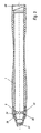
- FIG. 3 finally shows a cross-sectional view of the dental shown in FIG. 1 Handpiece, in particular the ring switch 9 is shown in detail.
- This Ring switch 9 comprises a ring extending around the dental handpiece 1 Actuating surface 24 which is supported on the inside with respect to contact springs 38. By pressing the actuating surface 24, contact means 32 are activated, which depend on set operating mode perform the functions described above. The pressed one Actuating surface 24 is released again from the contact springs 38 into the Starting position pushed outwards.
- the ring switch 9 shown in Fig. 3 has the Advantage on that by a single finger press of the switch regardless of the location the handpiece 1 can be easily operated in the hand of the dentist. His Both longitudinal ends of the dental handpiece 1 have cavities 37 and 28 respectively Inclusion of the light probe or the supply hose.
- a suitable interface 39 for a Data transmission to an external computer may be provided.
- an optocoupler instead of an electrical one can be used for data transmission Data transmission path can be used.
Landscapes
- Health & Medical Sciences (AREA)
- Life Sciences & Earth Sciences (AREA)
- Surgery (AREA)
- Biophysics (AREA)
- Pathology (AREA)
- Engineering & Computer Science (AREA)
- Biomedical Technology (AREA)
- Heart & Thoracic Surgery (AREA)
- Medical Informatics (AREA)
- Molecular Biology (AREA)
- Physics & Mathematics (AREA)
- Animal Behavior & Ethology (AREA)
- General Health & Medical Sciences (AREA)
- Public Health (AREA)
- Veterinary Medicine (AREA)
- Audiology, Speech & Language Pathology (AREA)
- Dentistry (AREA)
- Oral & Maxillofacial Surgery (AREA)
- Dental Tools And Instruments Or Auxiliary Dental Instruments (AREA)
- Investigating, Analyzing Materials By Fluorescence Or Luminescence (AREA)
- Measuring And Recording Apparatus For Diagnosis (AREA)
Claims (30)
- Procédé de localisation d'une zone ayant une activité de fluorescence accrue sur un objet à examiner (8) ayant la forme d'un tissu corporel humain ou animal, en particulier sur une dent, comportant les étapes :a) irradiation de l'objet à examiner (8) avec un rayon d'excitation (11),b) enregistrement d'une valeur instantanée du rayonnement de fluorescence (20) provoqué sur l'objet par le rayon d'excitation,c) comparaison de la valeur instantanée avec une valeur de pointe du rayonnement de fluorescence déterminée au préalable pendant la mesure, qui correspond à une région de l'objet examiné ayant la plus forte activité de fluorescence etd) localisation de la région ayant la plus forte activité de fluorescence lorsque la valeur instantanée coïncide avec la valeur de pointe.
- Procédé selon la revendication 1,
caractérisé en ce que,
la valeur de pointe est déterminée par :enregistrement d'une valeur instantanée du rayonnement de fluorescence (20) provoqué sur l'objet examiné par le rayon d'excitation,comparaison de la valeur instantanée avec la valeur de pointe antérieurement trouvée et mémorisation de la valeur instantanée en tant que nouvelle valeur de pointe si la valeur instantanée est supérieure à la valeur de pointe antérieurement trouvée etrépétition de ces étapes jusqu'à la fin de l'opération de mesure. - Procédé selon la revendication 1 ou 2,
caractérisé en ce que,
on procède à un ajustement avant de commencer la mesure, moyennant quoi la mesure est adaptée à la fluorescence propre de l'objet à examiner (8) et la valeur instantanée remise à zéro. - Procédé selon l'une quelconque des revendications 1 à 3,
caractérisé en ce que,
le rayonnement de fluorescence des moyens de détection correspondants (2) est détecté, un calibrage des nouveaux moyens de détection étant réalisé à l'aide de deux pièces de référence prédéfinies avant l'utilisation de nouveaux moyens de détection. - Procédé selon les revendications 3 et 4,
caractérisé en ce que,
le calibrage est réalisé en mode de calibrage via un élément de commutation (9), en ce que l'alignement est réalisé en mode de mesure par le même élément de commutation (9) en activant l'élément de commutation pendant un temps donné, et en ce qu'en mode de mesure une valeur de pointe mémorisée est supprimée en actionnant plusieurs fois le même élément de commutation (9) dans les limites d'un intervalle de temps donné. - Dispositif pour déterminer la présence de caries, de plaque dentaire ou d'attaque bactérienne sur des dents qui fonctionne à l'aide d'une tension d'alimentation, ayantcaractérisé pardes moyens (10) pour produire un rayon d'excitation (11) servant à irradier une dent à examiner (8),des moyens de détection (2) pour la détection d'une valeur instantanée du rayonnement de fluorescence (20) provoqué sur l'objet par le rayon d'excitation etdes moyens de mémorisation (31) pour mémoriser la valeur de pointe du rayonnement de fluorescence détecté (20) obtenue pendant une période de mesure donnée,
des moyens (29) permettant la comparaison de la valeur instantanée avec la valeur de pointe. - Dispositif selon la revendication 6,
caractérisé par
des moyens d'affichage (13, 14) permettant l'affichage de la valeur instantanée et de la valeur de pointe du rayonnement de fluorescence obtenue pendant la période de mesure donnée. - Dispositif selon la revendication 6 ou 7,
caractérisé par
des moyens (9) permettant l'effacement des moyens de mémorisation (31) qui mémorisent la valeur de pointe. - Dispositif selon l'une quelconque des revendications 6 à 8,
caractérisé par
des moyens (9) permettant l'ajustement du dispositif, moyennant quoi le dispositif est adapté à la fluorescence propre de la dent à examiner (8). - Dispositif selon la revendication 8 ou 9,
caractérisé en ce que,
les moyens permettant l'effacement des moyens de mémorisation (31) mémorisant la valeur de pointe et les moyens permettant l'ajustement du dispositif sont réalisés par un et même élément de commutation (9) dont la fonction est déterminée en fonction de sa durée d'activation et de sa séquence d'activation. - Dispositif selon la revendication 10,
caractérisé en ce que,
l'élément de commutation (9) est formé par un commutateur s'étendant en forme d'anneau, avec sa face de commutation, autour d'un porte-outil dentaire (1), le porte-outil dentaire (1) servant à redresser le rayon d'excitation (11) et portant les moyens de détection (2). - Dispositif selon l'une quelconque des revendications 6 à 11,
caractérisé par,
des moyens (1) permettant le calibrage des moyens de détection (2) à l'aide d'une pièce de référence ou de deux pièces de référence qui sont fabriquées en particulier en céramique. - Dispositif selon l'une quelconque des revendications 6 à 12,
caractérisé par,
une fixation (19) destinée à un porte-outil dentaire (1) du dispositif, pouvant être disposée en haut et/ou sur le côté d'un boítier (12) du dispositif, la fixation pouvant tourner par paliers ou en continu. - Dispositif selon l'une quelconque des revendications 6 à 13,
caractérisé en ce que,
les moyens de détection (2) sont interchangeables et en ce que des moyens d'affichage (15a - 15c) permettant l'affichage des moyens de détection choisis sont présents. - Dispositif selon la revendication 14,
caractérisé par
des moyens (6) permettant de choisir les moyens de détection (2). - Dispositif selon la revendication 14 ou 15,
caractérisé par
des moyens de mémorisation (26) permettant la mémorisation du dernier moyen de détection (2) utilisé. - Dispositif selon l'une quelconque des revendications 14 à 16 et la revendication 9,
caractérisé par,
des moyens de mémorisation (25) permettant la mémorisation des valeurs d'ajustement des différents moyens de détection (2). - Dispositif selon l'une quelconque des revendications 14 à 17 et la revendication 12,
caractérisé par,
des moyens de mémorisation (23) permettant la mémorisation des valeurs de calibrage des différents moyens de détection (2). - Dispositif selon l'une quelconque des revendications 6 à 18,
caractérisé par,
des moyens (16) permettant l'émission d'un signal d'alerte si la tension d'alimentation du dispositif est tombée en dessous d'une valeur limite donnée. - Dispositif selon l'une quelconque des revendications 6 à 19,
caractérisé par,
des moyens (33) permettant la déconnexion automatique d'une alimentation en tension (21) du dispositif fournissant la tension d'alimentation, si ce dispositif n'est pas activé dans un intervalle de temps donné. - Dispositif selon l'une quelconque des revendications 6 à 20,
caractérisé par,
des moyens (34) permettant la détection du temps de fonctionnement total du dispositif. - Dispositif selon l'une quelconque des revendications 6 à 21,
caractérisé en ce que,
les moyens (10) permettant la production d'un rayon d'excitation (11) produisent de la lumière laser en tant que rayon d'excitation et en ce que des moyens (35) destinés au courant laser de surveillance des moyens (10) produisant la lumière laser sont présents, qui produisent un signal d'alerte si le courant laser est baissé en dessous d'une valeur limite donnée ou est augmenté en dessus d'une valeur limite donnée. - Dispositif selon l'une quelconque des revendications 6 à 22,
caractérisé par,
des moyens (30) permettant l'émission d'un signal acoustique dépendant de la valeur instantanée, la fréquence du signal augmentant avec la valeur instantanée. - Dispositif selon la revendication 23,
caractérisé en ce que,
le signal acoustique n'est émis que si la valeur instantanée augmente. - Dispositif selon la revendication 23,
caractérisé en ce que,
le signal acoustique n'est émis que si la valeur instantanée coïncide avec la valeur de pointe. - Dispositif selon l'une quelconque des revendications 6 à 25,
caractérisé en ce que,
des moyens (39) permettant la transmission à un calculateur des valeurs détectées par les moyens de détection (2) pouvant être raccordé, sont présents. - Dispositif selon la revendication 26,
caractérisé en ce que,
les moyens de transmission (39) comportent un optocoupleur. - Dispositif selon l'une quelconque des revendications 6 à 27,
caractérisé par,
un dispositif d'alimentation en tension (21) qui fournit la tension d'alimentation pour le fonctionnement du dispositif et est constitué d'un accumulateur ou d'une batterie. - Dispositif selon l'une quelconque des revendications 6 à 28
caractérisé par,
des moyens de fixation permettant la fixation du dispositif sur un poste de travail dentaire. - Dispositif selon la revendication 29,
caractérisé en ce que,
les moyens de fixation sont équipés de manière à permettre la rotation et/ou le basculement du dispositif sur le poste de travail.
Applications Claiming Priority (2)
| Application Number | Priority Date | Filing Date | Title |
|---|---|---|---|
| DE19709500A DE19709500C1 (de) | 1997-03-07 | 1997-03-07 | Verfahren und Vorrichtung zum Ermitteln von Karies an Zähnen |
| DE19709500 | 1997-03-07 |
Publications (3)
| Publication Number | Publication Date |
|---|---|
| EP0862897A2 EP0862897A2 (fr) | 1998-09-09 |
| EP0862897A3 EP0862897A3 (fr) | 2001-07-11 |
| EP0862897B1 true EP0862897B1 (fr) | 2004-08-11 |
Family
ID=7822650
Family Applications (1)
| Application Number | Title | Priority Date | Filing Date |
|---|---|---|---|
| EP98103930A Expired - Lifetime EP0862897B1 (fr) | 1997-03-07 | 1998-03-05 | Procédé pour mesurer la fluorescence et dispositif pour détecter des caries dentaires |
Country Status (5)
| Country | Link |
|---|---|
| US (1) | US6102704A (fr) |
| EP (1) | EP0862897B1 (fr) |
| JP (1) | JPH1142242A (fr) |
| AT (1) | ATE272974T1 (fr) |
| DE (2) | DE19709500C1 (fr) |
Families Citing this family (33)
| Publication number | Priority date | Publication date | Assignee | Title |
|---|---|---|---|---|
| DE29705934U1 (de) * | 1997-04-03 | 1997-06-05 | Kaltenbach & Voigt Gmbh & Co, 88400 Biberach | Diagnose- und Behandlungsvorrichtung für Zähne |
| GB9810471D0 (en) * | 1998-05-16 | 1998-07-15 | Helmet Hund Gmbh | Toothbrush |
| DE19827417B4 (de) * | 1998-06-19 | 2004-10-28 | Hahn, Rainer, Dr.Med.Dent. | Material zur unterschiedlichen Modifizierung der optischen Eigenschaften unterschiedlicher Zellen |
| NL1012012C2 (nl) * | 1999-05-10 | 2000-11-23 | Inspektor Res Systems B V | Werkwijze en inrichting voor het bepalen van cariÙsactiviteit van een carieuze laesie in een tand. |
| CA2297476A1 (fr) * | 2000-01-21 | 2001-07-21 | Neks Recherche & Developpement Inc. | Systeme pour la detection de tartre dentaire, i.e. tartre subgingival |
| DE10013210A1 (de) | 2000-03-17 | 2001-09-20 | Kaltenbach & Voigt | Vorrichtung zum Erkennen von Karies, Plaque, bakteriellen Befall, Konkrementen, Zahnstein und anderen fluoreszierenden Substanzen an Zähnen |
| CA2341105A1 (fr) | 2001-03-21 | 2002-09-21 | Unknown | Systeme et methode de detection et d'elimination du tartre, p. ex. du tartre sous-gingival |
| US6769911B2 (en) | 2001-04-16 | 2004-08-03 | Advanced Research & Technology Institue | Luminescence assisted caries excavation |
| KR20030047139A (ko) * | 2001-12-08 | 2003-06-18 | 이상호 | 광학적 치아우식활성검사법 |
| CA2385981A1 (fr) * | 2002-05-08 | 2003-11-08 | Neks Recherche & Developpement Inc. | Appareil et methode de detection des caries dentaires |
| WO2005013843A2 (fr) * | 2003-08-08 | 2005-02-17 | The Regents Of The Univeristy Of California | Diaphanoscopie dans l'infrarouge proche pour imagerie de carie dentaire recente |
| DE102004024164A1 (de) * | 2004-05-14 | 2005-12-08 | Kaltenbach & Voigt Gmbh & Co. Kg | Zahnärztliches System zum Untersuchen der optischen Eigenschaften von Zahngewebe mit optischer Untersuchungsvorrichtung und Abgleicheinrichtung |
| DE102004024165A1 (de) | 2004-05-14 | 2005-12-01 | Kaltenbach & Voigt Gmbh & Co. Kg | Zahnärztliche Vorrichtung zum Untersuchen der optischen Eigenschaften von Zahngewebe |
| DE102004029033A1 (de) * | 2004-06-09 | 2006-01-05 | Alfred Kärcher Gmbh & Co. Kg | Mobile Sanitäranlage zur ortsunabhängigen sanitären Versorgung einer Vielzahl von Personen |
| US7270543B2 (en) * | 2004-06-29 | 2007-09-18 | Therametric Technologies, Inc. | Handpiece for caries detection |
| DE102005052294A1 (de) | 2005-10-26 | 2007-05-03 | Jaruszewski, Lutz, Dr. | Messvorrichtung und Verfahren zur Bestimmung des Aktivitätsstatus initialkariöser Schmelzläsionen |
| US8647119B1 (en) * | 2006-04-18 | 2014-02-11 | President And Fellows Of Harvard College | Methods and kits with fluorescent probes for caries detection |
| US8360771B2 (en) * | 2006-12-28 | 2013-01-29 | Therametric Technologies, Inc. | Handpiece for detection of dental demineralization |
| EP2330966B1 (fr) * | 2008-08-25 | 2013-06-19 | Koninklijke Philips Electronics N.V. | Systeme de detection, traitement, et reponse de couverture d affections buccales |
| US20100279248A1 (en) * | 2009-03-05 | 2010-11-04 | Mourad Pierre D | Device and method for predicting the likelihood of caries development |
| US8641415B2 (en) * | 2010-01-17 | 2014-02-04 | Kallis Technical Services | Method and apparatus for tooth crack detection by means of acoustic emission |
| EP2578200B1 (fr) | 2011-10-04 | 2018-03-28 | VOCO GmbH | Compositions pour l'infiltration et/ou le scellement de la matière dentaire dure et procédé correspondant |
| US9517015B2 (en) | 2012-12-21 | 2016-12-13 | Koninklijke Philips N.V. | Dental apparatus and method of utilizing the same |
| GB201420273D0 (en) | 2014-11-14 | 2014-12-31 | Mars Inc | Method for quantifying plaque in pet animals |
| EP4418279A3 (fr) * | 2015-12-04 | 2024-11-27 | 3Shape A/S | Dérivation d'informations d'état de dent pour garnir des graphiques dentaires numériques |
| MX2018012631A (es) | 2016-04-13 | 2019-07-08 | Inspektor Res Systems B V | Examinación dental de dos frecuencias. |
| JPWO2018207471A1 (ja) * | 2017-05-09 | 2020-05-14 | ソニー株式会社 | 制御装置、制御システム、制御方法、及びプログラム |
| US11116568B2 (en) | 2017-06-23 | 2021-09-14 | Oral Diagnostix, Llc | Transoral ultrasound probe and method of use |
| US11464467B2 (en) * | 2018-10-30 | 2022-10-11 | Dgnct Llc | Automated tooth localization, enumeration, and diagnostic system and method |
| US10991091B2 (en) * | 2018-10-30 | 2021-04-27 | Diagnocat Inc. | System and method for an automated parsing pipeline for anatomical localization and condition classification |
| US20230034006A1 (en) * | 2019-12-06 | 2023-02-02 | Pds Inc. | Dental tool having a thermoelectric device |
| JPWO2022269877A1 (fr) * | 2021-06-24 | 2022-12-29 | ||
| EP4309562A1 (fr) * | 2022-07-20 | 2024-01-24 | Ivoclar Vivadent AG | Unité d'étalonnage pour un dispositif d'imagerie médicale macroscopique, système d'étalonnage d'imagerie médicale macroscopique et utilisation d'une unité d'étalonnage |
Family Cites Families (10)
| Publication number | Priority date | Publication date | Assignee | Title |
|---|---|---|---|---|
| US4290433A (en) * | 1979-08-20 | 1981-09-22 | Alfano Robert R | Method and apparatus for detecting the presence of caries in teeth using visible luminescence |
| US4479499A (en) * | 1982-01-29 | 1984-10-30 | Alfano Robert R | Method and apparatus for detecting the presence of caries in teeth using visible light |
| DE3345465A1 (de) * | 1983-12-15 | 1985-06-27 | Siemens AG, 1000 Berlin und 8000 München | Zahnaerztliches diagnosegeraet |
| US5259761A (en) * | 1990-08-06 | 1993-11-09 | Jenifer M. Schnettler | Tooth vitality probe and process |
| DE4200741C2 (de) * | 1992-01-14 | 2000-06-15 | Kaltenbach & Voigt | Einrichtung zum Erkennen von Karies an Zähnen |
| US5382163A (en) * | 1992-07-20 | 1995-01-17 | Putnam; David L. | Method and apparatus for detecting the presence of dental plaque or calculus |
| DE9317984U1 (de) * | 1993-11-24 | 1995-03-23 | Kaltenbach & Voigt Gmbh & Co, 88400 Biberach | Vorrichtung zum Erkennen von Karies |
| US5759030A (en) * | 1996-01-02 | 1998-06-02 | Lj Laboratories, L.L.C. | Method for determing optical characteristics of teeth |
| IL119701A0 (en) * | 1996-11-26 | 1997-02-18 | Novadent Ltd | Device and method for the ultrasonic detection of dental caries |
| DE19709499A1 (de) * | 1997-03-07 | 1998-09-17 | Kaltenbach & Voigt | Zahnärztliche Behandlungsvorrichtung |
-
1997
- 1997-03-07 DE DE19709500A patent/DE19709500C1/de not_active Expired - Fee Related
-
1998
- 1998-03-04 US US09/034,843 patent/US6102704A/en not_active Expired - Lifetime
- 1998-03-05 DE DE59811777T patent/DE59811777D1/de not_active Expired - Lifetime
- 1998-03-05 EP EP98103930A patent/EP0862897B1/fr not_active Expired - Lifetime
- 1998-03-05 AT AT98103930T patent/ATE272974T1/de active
- 1998-03-09 JP JP10056860A patent/JPH1142242A/ja active Pending
Also Published As
| Publication number | Publication date |
|---|---|
| DE59811777D1 (de) | 2004-09-16 |
| EP0862897A3 (fr) | 2001-07-11 |
| DE19709500C1 (de) | 1998-07-23 |
| US6102704A (en) | 2000-08-15 |
| EP0862897A2 (fr) | 1998-09-09 |
| JPH1142242A (ja) | 1999-02-16 |
| ATE272974T1 (de) | 2004-08-15 |
Similar Documents
| Publication | Publication Date | Title |
|---|---|---|
| EP0862897B1 (fr) | Procédé pour mesurer la fluorescence et dispositif pour détecter des caries dentaires | |
| DE60316699T2 (de) | Dentalgerät zur untersuchung der zahnoberfläche | |
| EP0862896A2 (fr) | Dispositif pour la détection des caries, de la plaque ou de l'attaque bactérienne dentaire | |
| DE69918549T2 (de) | Gerät zur feststellung von zahnbelag mittels fluoreszenzmessung | |
| EP0774235B1 (fr) | Dispositif destiné à la détection de la caré, de la plaque ou de l'attaque bactérielle de la denture | |
| DE19755169C2 (de) | Periodontaltaschenmeßgerät | |
| DE10133451B4 (de) | Vorrichtung zum Erkennen von Karies, Plaque, Konkrementen oder bakteriellem Befall an Zähnen | |
| DE29705934U1 (de) | Diagnose- und Behandlungsvorrichtung für Zähne | |
| DE10236175B4 (de) | Lasersystem mit fasergebundener Kommunikation | |
| EP0962185B1 (fr) | Dispositif destiné à la détermination de la cariée, de la plaque, de concrétions ou d' affectations bactérielles des dents | |
| EP1136034A1 (fr) | Dispositif de détection de substances dentaires fluorescentes | |
| EP2074940A1 (fr) | Dispositif de traitement ou d'examen dentaire | |
| EP1372518B1 (fr) | Appareil de traitement laser dote d'un systeme d'eclairage | |
| EP0555645A1 (fr) | Dispositif pour détecter la carie dentaire | |
| EP2260761A1 (fr) | Dispositif dentaire pour l'examen de charactéristiques optiques dentaires | |
| DE112004003014T5 (de) | Optische Zahndiagnosevorrichtung | |
| EP3213675A1 (fr) | Dispositif et procédé de tomographie optique par cohérence double (otc) sur l'oreille moyenne humaine | |
| DE102006041020B4 (de) | System zum Transilluminieren von Zähnen und Kopfstück hierfür | |
| DE10249674A1 (de) | Operationsinstrument zum Schneiden, Abtragen oder Absaugen von Material in einem Operationsgebiet | |
| DE10043749A1 (de) | Zahnmedizinisches Handstück | |
| DE20209441U1 (de) | Vorrichtung zum Erkennen von bakteriellem Befall an Zähnen | |
| EP2520221A1 (fr) | Pièce manuelle pour un appareil de diagnostic médical et appareil de diagnostic médical | |
| EP4215152B1 (fr) | Appareil dentaire portatif permettant de durcir la matière et d'exciter la fluorescence | |
| DE10333515B4 (de) | Verfahren und Vorrichtung zum Kenntlichmachen von zahnfarbenen Zahnfüllungsresten | |
| EP1595494A1 (fr) | Système dentaire pour l'examen de charactéristiques optiques du tissue dentaire avec dispositif d'examen optique et dispositif de calibration |
Legal Events
| Date | Code | Title | Description |
|---|---|---|---|
| PUAI | Public reference made under article 153(3) epc to a published international application that has entered the european phase |
Free format text: ORIGINAL CODE: 0009012 |
|
| AK | Designated contracting states |
Kind code of ref document: A2 Designated state(s): AT CH DE FR IT LI |
|
| AX | Request for extension of the european patent |
Free format text: AL;LT;LV;MK;RO;SI |
|
| PUAL | Search report despatched |
Free format text: ORIGINAL CODE: 0009013 |
|
| AK | Designated contracting states |
Kind code of ref document: A3 Designated state(s): AT BE CH DE DK ES FI FR GB GR IE IT LI LU MC NL PT SE |
|
| AX | Request for extension of the european patent |
Free format text: AL;LT;LV;MK;RO;SI |
|
| 17P | Request for examination filed |
Effective date: 20011114 |
|
| AKX | Designation fees paid |
Free format text: AT CH DE FR IT LI |
|
| RAP1 | Party data changed (applicant data changed or rights of an application transferred) |
Owner name: KALTENBACH & VOIGT GMBH & CO. KG |
|
| 17Q | First examination report despatched |
Effective date: 20030822 |
|
| GRAP | Despatch of communication of intention to grant a patent |
Free format text: ORIGINAL CODE: EPIDOSNIGR1 |
|
| RTI1 | Title (correction) |
Free format text: FLUORESCENCE MEASUREMENT METHOD AND DEVICE FOR DETECTING DENTAL CARIES |
|
| RTI1 | Title (correction) |
Free format text: FLUORESCENCE MEASUREMENT METHOD AND DEVICE FOR DETECTING DENTAL CARIES |
|
| GRAS | Grant fee paid |
Free format text: ORIGINAL CODE: EPIDOSNIGR3 |
|
| GRAA | (expected) grant |
Free format text: ORIGINAL CODE: 0009210 |
|
| AK | Designated contracting states |
Kind code of ref document: B1 Designated state(s): AT CH DE FR IT LI |
|
| REG | Reference to a national code |
Ref country code: CH Ref legal event code: EP |
|
| REG | Reference to a national code |
Ref country code: CH Ref legal event code: NV Representative=s name: A. BRAUN, BRAUN, HERITIER, ESCHMANN AG PATENTANWAE |
|
| REF | Corresponds to: |
Ref document number: 59811777 Country of ref document: DE Date of ref document: 20040916 Kind code of ref document: P |
|
| ET | Fr: translation filed | ||
| PLBE | No opposition filed within time limit |
Free format text: ORIGINAL CODE: 0009261 |
|
| STAA | Information on the status of an ep patent application or granted ep patent |
Free format text: STATUS: NO OPPOSITION FILED WITHIN TIME LIMIT |
|
| 26N | No opposition filed |
Effective date: 20050512 |
|
| REG | Reference to a national code |
Ref country code: CH Ref legal event code: PFA Owner name: KALTENBACH & VOIGT GMBH & CO. KG Free format text: KALTENBACH & VOIGT GMBH & CO. KG#BISMARCKRING 39#88400 BIBERACH/RISS (DE) -TRANSFER TO- KALTENBACH & VOIGT GMBH & CO. KG#BISMARCKRING 39#88400 BIBERACH/RISS (DE) |
|
| PGFP | Annual fee paid to national office [announced via postgrant information from national office to epo] |
Ref country code: IT Payment date: 20110323 Year of fee payment: 14 Ref country code: FR Payment date: 20110401 Year of fee payment: 14 Ref country code: AT Payment date: 20110328 Year of fee payment: 14 |
|
| PGFP | Annual fee paid to national office [announced via postgrant information from national office to epo] |
Ref country code: CH Payment date: 20110405 Year of fee payment: 14 Ref country code: DE Payment date: 20110411 Year of fee payment: 14 |
|
| REG | Reference to a national code |
Ref country code: CH Ref legal event code: PL |
|
| REG | Reference to a national code |
Ref country code: AT Ref legal event code: MM01 Ref document number: 272974 Country of ref document: AT Kind code of ref document: T Effective date: 20120305 |
|
| REG | Reference to a national code |
Ref country code: FR Ref legal event code: ST Effective date: 20121130 |
|
| PG25 | Lapsed in a contracting state [announced via postgrant information from national office to epo] |
Ref country code: FR Free format text: LAPSE BECAUSE OF NON-PAYMENT OF DUE FEES Effective date: 20120402 Ref country code: CH Free format text: LAPSE BECAUSE OF NON-PAYMENT OF DUE FEES Effective date: 20120331 Ref country code: LI Free format text: LAPSE BECAUSE OF NON-PAYMENT OF DUE FEES Effective date: 20120331 Ref country code: AT Free format text: LAPSE BECAUSE OF NON-PAYMENT OF DUE FEES Effective date: 20120305 |
|
| REG | Reference to a national code |
Ref country code: DE Ref legal event code: R119 Ref document number: 59811777 Country of ref document: DE Effective date: 20121002 |
|
| PG25 | Lapsed in a contracting state [announced via postgrant information from national office to epo] |
Ref country code: IT Free format text: LAPSE BECAUSE OF NON-PAYMENT OF DUE FEES Effective date: 20120305 |
|
| PG25 | Lapsed in a contracting state [announced via postgrant information from national office to epo] |
Ref country code: DE Free format text: LAPSE BECAUSE OF NON-PAYMENT OF DUE FEES Effective date: 20121002 |