EP0863236B1 - Schussfadenspeichervorrichtung, insbesondere zum Zuführen von Fäden aus Metall, Nylon und dergleichen in Webmaschinen - Google Patents
Schussfadenspeichervorrichtung, insbesondere zum Zuführen von Fäden aus Metall, Nylon und dergleichen in Webmaschinen Download PDFInfo
- Publication number
- EP0863236B1 EP0863236B1 EP19980102124 EP98102124A EP0863236B1 EP 0863236 B1 EP0863236 B1 EP 0863236B1 EP 19980102124 EP19980102124 EP 19980102124 EP 98102124 A EP98102124 A EP 98102124A EP 0863236 B1 EP0863236 B1 EP 0863236B1
- Authority
- EP
- European Patent Office
- Prior art keywords
- drum
- thread
- weft thread
- preparation device
- disk
- Prior art date
- Legal status (The legal status is an assumption and is not a legal conclusion. Google has not performed a legal analysis and makes no representation as to the accuracy of the status listed.)
- Expired - Lifetime
Links
- 238000009941 weaving Methods 0.000 title claims description 19
- 239000004677 Nylon Substances 0.000 title claims description 4
- 239000002184 metal Substances 0.000 title claims description 4
- 229920001778 nylon Polymers 0.000 title claims description 4
- 125000006850 spacer group Chemical group 0.000 claims description 2
- 230000000284 resting effect Effects 0.000 description 6
- 238000009825 accumulation Methods 0.000 description 1
- 230000015572 biosynthetic process Effects 0.000 description 1
- 230000002860 competitive effect Effects 0.000 description 1
- 230000000694 effects Effects 0.000 description 1
- 239000004744 fabric Substances 0.000 description 1
- 230000000670 limiting effect Effects 0.000 description 1
- 239000000463 material Substances 0.000 description 1
- 230000004048 modification Effects 0.000 description 1
- 238000012986 modification Methods 0.000 description 1
- 230000002093 peripheral effect Effects 0.000 description 1
- 239000007787 solid Substances 0.000 description 1
- 229920002994 synthetic fiber Polymers 0.000 description 1
- 239000012209 synthetic fiber Substances 0.000 description 1
- 239000004753 textile Substances 0.000 description 1
Images
Classifications
-
- D—TEXTILES; PAPER
- D03—WEAVING
- D03D—WOVEN FABRICS; METHODS OF WEAVING; LOOMS
- D03D47/00—Looms in which bulk supply of weft does not pass through shed, e.g. shuttleless looms, gripper shuttle looms, dummy shuttle looms
- D03D47/34—Handling the weft between bulk storage and weft-inserting means
-
- B—PERFORMING OPERATIONS; TRANSPORTING
- B65—CONVEYING; PACKING; STORING; HANDLING THIN OR FILAMENTARY MATERIAL
- B65H—HANDLING THIN OR FILAMENTARY MATERIAL, e.g. SHEETS, WEBS, CABLES
- B65H51/00—Forwarding filamentary material
- B65H51/20—Devices for temporarily storing filamentary material during forwarding, e.g. for buffer storage
- B65H51/22—Reels or cages, e.g. cylindrical, with storing and forwarding surfaces provided by rollers or bars
-
- D—TEXTILES; PAPER
- D03—WEAVING
- D03D—WOVEN FABRICS; METHODS OF WEAVING; LOOMS
- D03D47/00—Looms in which bulk supply of weft does not pass through shed, e.g. shuttleless looms, gripper shuttle looms, dummy shuttle looms
- D03D47/34—Handling the weft between bulk storage and weft-inserting means
- D03D47/345—Rotating bobbins
-
- B—PERFORMING OPERATIONS; TRANSPORTING
- B65—CONVEYING; PACKING; STORING; HANDLING THIN OR FILAMENTARY MATERIAL
- B65H—HANDLING THIN OR FILAMENTARY MATERIAL, e.g. SHEETS, WEBS, CABLES
- B65H2701/00—Handled material; Storage means
- B65H2701/30—Handled filamentary material
- B65H2701/31—Textiles threads or artificial strands of filaments
Definitions
- the present invention relates to a weft thread preparation device, particularly for feeding threads made of metal, nylon and the like to machines for weaving.
- the thread is not subjected, during unwinding, to permanent deformations that can damage its characteristics.
- a first conventional kind of device is provided with a fixed drum constituted by two facing parallel disks which are mutually connected by threaded pivots which can rotate about their own axis.
- An arm arranged outside the drum unwinds the weft thread from the corresponding spool and winds it on the threaded pivots, which rotate about their own axes under the force applied by the thread and move the thread from one of their ends to the other, where the thread is released from the drum in order to feed it to the weaving loom.
- the thread also passes from the spool to the drum by means of the arm along a path which is not straight but is instead constituted by a series of curves which entail the forming of bends in the thread which can be permanent if the cross-section of said thread is significant.
- the weft thread fed to the weaving loom does not have characteristics that allow the loom to provide a fabric of the intended quality or cannot be woven at all.
- a second conventional kind of weft thread preparation device is provided with a solid drum which rotates about its own axis and on which the thread taken from the spool is wound.
- US-A-2 605 536 discloses a strand storage and advancement reel having a combination of elements as recited in the precharacterizing portion of the appended claim 1.
- the aim of the present invention is therefore to provide a weft thread preparation device for weaving looms which allows to feed the weft thread from the spool on which it is wound to the loom along a direct path without forming bends.
- an object of the present invention is to provide a weft thread preparation device for weaving looms which allows to unwind the thread from the corresponding spool with the spool arranged either horizontally or vertically with respect to the resting surface.
- Another object of the present invention is to provide a weft thread preparation device for weaving looms which allows to feed the weft thread in a controlled manner to the weaving loom.
- Another object of the present invention is to provide a weft thread preparation device for weaving looms which maintains a substantially constant tension on the thread.
- Another object of the present invention is to provide a weft thread preparation device which is highly reliable and relatively easy to provide at competitive costs.
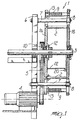
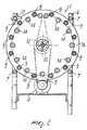
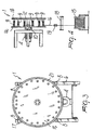
- the weft thread preparation device comprises a drum 1 which is constituted by two parallel facing disks 1a and 1b mutually connected by spacers 2 which are arranged circumferentially.
- the drum 1 is keyed on a shaft 3 which is actuated by a motor 4 by means of a driving belt 5 which engages a pulley 10.
- the drum 1 is supported by a supporting frame 6 which is constituted by a mounting provided with four arms 7 which protrude from the mounting and are suitable to form four resting points for the drum 1.
- each arm 7 there is provided a grooved wheel 8 which can rotate with respect to the corresponding arm 7.
- a total of four grooved wheels 8 are provided which constitute four supporting points within which the drum 1 rests so that it can rotate freely.
- the outer disk 1b of the drum 1 rests in the grooves of the four grooved wheels 8.
- threaded pivots 9 are arranged circumferentially and connect the disk la to the disk 1b of the drum 1.
- the thread of the pivots 9 is preferably provided along approximately three quarters of their length.
- the extension of the screw thread varies according to the number of turns of the thread 16 to be formed on the threaded pivots 9.
- the threaded pivots 9 can rotate about their own axis under the effect of the traction applied by kinematic means, as described hereinafter.
- Kinematic means conveniently constituted for example by a chain 11 and by a pinion 12 which is keyed on the shaft 3 and is arranged adjacent to the disk la, are provided for rotating the threaded pivots 9.
- Each threaded pivot 9 has a pinion 13 which is arranged adjacent to the disk la and is adapted to engage the chain 11 for rotating the pivot 9.
- the chain 11 is thus arranged so that it passes around each threaded pivot 9 after passing around the pinion 12 in order to receive the motion imparted by the driving shaft 3.
- sprockets 14 are provided and connected to the disk la in a staggered position and internally with respect to the plurality of threaded pivots 9. In this manner, the chain 11 follows a path around each sprocket 14 and each threaded pivot 9, so as to pass internally to each threaded pivot 9 relative to the edge of the disk 1a.
- each threaded pivot 9 rotates in the opposite direction with respect to the rotation of the drum 1, so as to maintain a correct tension of the weft thread 16 that winds on the threaded pivots 9.
- a feeder 17 is provided for passing the weft thread 16 that arrives from the spool 15 to the threaded pivots 9 of the drum 1.
- the thread 16 passes over a guiding roller 18, through a braking element 19 and finally through the feeder 17.
- a microswitch 20 located on the inner face of the disk 1b and actuated by a rod 22 is provided in order to stop the rotation of the drum 1 and therefore the unwinding of the thread 16 from the spool 15.
- the microswitch 20 has a contact which is grounded on a disk which is rigidly coupled to the driving shaft 3.
- the disk 1b is circumferentially provided with a groove for the exit of the thread 16 and for subsequently sending it to a weaving loom (not shown).
- the operation of the weft thread preparation device according to the present invention is as follows.
- the drum 1, keyed on the shaft 3, is rotated by the belt 5, which engages the pulley 10 which is rigidly coupled to the shaft 3 by means of the motor 4, and the rotation of the drum 1 allows the weft thread 16 to unwind from the corresponding spool 15 located at the base of the device according to the present invention.
- the thread 16 unwound from the spool 15 winds on the threaded pivots 9, which are in turn rotated by the chain 11, meshing with the pinion 12.
- the rotation of the drum 1 allows the thread 16 to unwind from the spool 15 without forming spirals, as usually occurs when the spool 15 is arranged so that its diametrical axis is perpendicular to the resting region.
- the rotation of the threaded pivots 9 causes the weft thread 16 to move along the screw thread of the pivots 9 in order to pass from a position in which it is adjacent to the disk la to a position in which it is adjacent to the disk 1b, from which it then exits through the groove formed in the disk 1b.
- the device according to the present invention fully achieves the intended aim, since it allows to prepare the weft thread, unwinding it from the corresponding spool, and to send it to the weaving loom along a substantially straight path without making the thread form undesirable bends and thus without damaging said thread.
- the spool on which the weft thread is initially wound can also be arranged so that its diametrical axis is parallel to the resting area of the device, so that the passage of the thread from the spool to the drum occurs along a substantially straight path.
- the sensor for detecting the accumulation of weft thread on the drum allows to stop the rotation of the drum when the weft thread on it has reached a preset number of turns, so as to match the unwinding of the thread from its spool with the speed with which said thread is taken up by the weaving loom.
- the spool 15 is shown arranged so that its diametrical axis is parallel to the resting region, but as mentioned, in the case of fine threads (wherein formation of spirals does not entail problems, since the thread is supple) it is possible to arrange the spool 15 so that its diametrical axis is perpendicular to the resting region.
- the chain 11 for rotating the threaded pivots 9 is also shown to pass on the inside of said pivots with respect to the peripheral rim of the disk la that constitutes one of the faces of the drum 1 and on which the chain 11 is arranged.
- this arrangement has been found to ensure optimum tensioning of the thread 16, making the threaded pivots 9 rotate in the opposite direction with respect to the drum 1, it is nonetheless possible to pass the chain 11 on the outside of the threaded pivots 9, so as to make them rotate in the same direction as the drum 1 (this alternative is not shown in the various figures).
- the pitch of the screw thread of the threaded pivots 9 is orientated in the opposite direction with respect to the one shown in the figures.
- the materials employed may be any according to requirements and the state of the art.
Landscapes
- Engineering & Computer Science (AREA)
- Textile Engineering (AREA)
- Looms (AREA)
- Forwarding And Storing Of Filamentary Material (AREA)
- Reinforced Plastic Materials (AREA)
Claims (7)
- Schussfadenherstellungsgerät für die Zufuhr von Fäden aus Metall, Nylon und dergleichen zu einem Webstuhl, der eine rotierende Trommel (1) umfasst, die auf einer Antriebswelle (3) und einer Vielzahl von reihum umfänglich angeordneten Gewindestiften (9), die um ihre eigene Achse rotieren können, versehen ist, wobei die Rotation der Trommel (1) zusammen mit der Rotation der Gewindestifte (9) geeignet Ist, die Rotation einer Spule (15) von Faden zu erzeugen, um den Faden (16) von der Spule (15) abzuwickeln und den Faden (16) entlang den Gewindestiften (9) zu bewegen, um den Faden (16) nach und nach zu einem Webstuhl zu führen, an dem mit der Antriebswelle (3) der Trommel (1) verbundene kinematische Mittel (11, 12) vorgesehen sind, um die Gewindestifte (9) gleichzeitig mit und als Folge der Rotation der Trommel (1) zu Rotieren, wobei die Trommel (1) eine erste Scheibe (1a) und eine zweite Scheibe (1b) umfasst, die einander gegenüber liegen und gegeneinander parallel angeordnet sind, dadurch gekennzeichnet, dass sie Mittel (20,22) zum Anhalten der Rotation der Trommel (1) aufweist, die auf der Trommel (1) angeordnet sind und geeignet sind, die Rotation zu unterbrechen, wenn eine bestimmte Anzahl von Umdrehungen des Fadens (16) auf den Gewindestiften (9) erreicht ist, wobei die Schließmittel einen Mikroschalter (20) umfassen, der durch einen Stab (22) betätigt wird, wobei sich der Stab (22) unter dem Gewicht des Fadens nach unten bewegen kann und auf der Trommel (1) in einer Position angeordnet ist, die nahe zu einem der Gewindestifte (9) liegt, wobei die kinematischen Mittel (11, 12) und die Schließmittel (20, 22) alle zusammen in einem Zwischenraum angeordnet sind, der durch die sich gegenüberliegende erste Scheibe (1a) und die zweite Scheibe (1b) definiert ist
- Schussfadenherstellungsgerät gemäß Anspruch 1, dadurch gekennzeichnet, dass die erste Scheibe (1a) und die zweite Scheibe (1b) gegenseitig mit Abstandhaltem (2) verbunden sind.
- Schussfadenherstellungsgerät gemäß Anspruch 2, dadurch gekennzeichnet, dass die Trommel (1) auf der Welle (3) befestigt ist, die durch einen Motor (4) mit einem Riemenscheibenantrieb (5, 10) angetrieben ist.
- Schussfadenherstellungsgerät gemäß Anspruch 3, dadurch gekennzeichnet, dass jeder der Vielzahl der Gewindestifte (9) ein Treibrad (13) aufweist, das nahe der ersten Trommel (1a) angeordnet ist.
- Schussfadenherstellungsgerät gemäß Anspruch 4, dadurch gekennzeichnet, dass die kinematischen Mittel (11, 12) mit der Welle (3) und entsprechend mit dem Treibrad (13) jedes der Vielzahl der Gewindestifte (9) verbunden sind.
- Schussfadenherstellungsgerät gemäß Anspruch 5, dadurch gekennzeichnet, dass die kinematischen Mittel ein Treibrad (12), das auf der Welle (3) befestigt ist und in der Nähe der ersten Scheibe (1a) liegt und eine Kette (11) aufweisen, die geeignet ist, in das Treibrad (12) und die Treibräder (13) der Vielzahl der Gewindestifte (9) einzugreifen.
- Schussfadenherstellungsgerät gemäß Anspruch 6, dadurch gekennzeichnet, dass die kinematischen Mittel eine Vielzahl von Ritzeln (14) aufweisen, die so angeordnet sind, dass sie in Bezug auf die Vielzahl der Gewindestifte (9) abwechselnd und zickzackförmig angeordnet sind, wobei die Kette (11) so angeordnet ist, dass sie in die Ritzel (14) und die Treibräder (13) der Gewindestifte (9) eingreift.
Applications Claiming Priority (2)
| Application Number | Priority Date | Filing Date | Title |
|---|---|---|---|
| ITMI970283 | 1997-02-12 | ||
| ITMI970283 IT1290300B1 (it) | 1997-02-12 | 1997-02-12 | Dispositivo preparatore del filo di trama,particolarmente per l'alimentazione di fili metallici,di nylon e simili a telai di |
Publications (2)
| Publication Number | Publication Date |
|---|---|
| EP0863236A1 EP0863236A1 (de) | 1998-09-09 |
| EP0863236B1 true EP0863236B1 (de) | 2003-05-07 |
Family
ID=11375967
Family Applications (1)
| Application Number | Title | Priority Date | Filing Date |
|---|---|---|---|
| EP19980102124 Expired - Lifetime EP0863236B1 (de) | 1997-02-12 | 1998-02-06 | Schussfadenspeichervorrichtung, insbesondere zum Zuführen von Fäden aus Metall, Nylon und dergleichen in Webmaschinen |
Country Status (3)
| Country | Link |
|---|---|
| EP (1) | EP0863236B1 (de) |
| DE (1) | DE69814215T2 (de) |
| IT (1) | IT1290300B1 (de) |
Families Citing this family (1)
| Publication number | Priority date | Publication date | Assignee | Title |
|---|---|---|---|---|
| DE19942121A1 (de) * | 1999-09-03 | 2001-03-08 | Iro Patent Ag Baar | Verfahren zum Steuern eines Fadenverarbeitungssystems und Fadenverarbeitungssystem |
Family Cites Families (5)
| Publication number | Priority date | Publication date | Assignee | Title |
|---|---|---|---|---|
| US2605536A (en) * | 1947-07-12 | 1952-08-05 | Cyril A Litzler | Reel |
| US2609587A (en) * | 1950-05-17 | 1952-09-09 | Kuljian Harry Asdour | Filament storing and advancing reel |
| US4026484A (en) * | 1971-06-19 | 1977-05-31 | Pavena Ag | Apparatus for controlling a winding device for a continuously supplied fiber sliver |
| US3774384A (en) * | 1972-02-28 | 1973-11-27 | Leesona Corp | Yarn processing post treatment |
| IT1133857B (it) * | 1980-02-05 | 1986-07-24 | Vysoka Skola Strojni Textilni | Procedimento per regolare la velocita' e la densita' dell'avvolgimento di filato e la formazione di una sua scorta nonche' disposizione per la realizzazione di questo procedimento |
-
1997
- 1997-02-12 IT ITMI970283 patent/IT1290300B1/it active IP Right Grant
-
1998
- 1998-02-06 EP EP19980102124 patent/EP0863236B1/de not_active Expired - Lifetime
- 1998-02-06 DE DE1998614215 patent/DE69814215T2/de not_active Expired - Lifetime
Also Published As
| Publication number | Publication date |
|---|---|
| EP0863236A1 (de) | 1998-09-09 |
| IT1290300B1 (it) | 1998-10-22 |
| DE69814215T2 (de) | 2004-03-18 |
| ITMI970283A1 (it) | 1998-08-12 |
| DE69814215D1 (de) | 2003-06-12 |
Similar Documents
| Publication | Publication Date | Title |
|---|---|---|
| US4003525A (en) | Strip material unwinding device | |
| CS229913B2 (en) | Device for winding waste binding yarns in shuttleless looms | |
| US3940079A (en) | Yarn feeding device with constant adjustable tension, particularly for feeding yarns to weaving and knitting machines and devices | |
| CN101994188B (zh) | 提花链整经机和用于产生提花链的方法 | |
| EP0863236A1 (de) | Schussfadenspeichervorrichtung, insbesondere zum Zuführen von Fäden aus Metall, Nylon und dergleichen in Webmaschinen | |
| JPS6411543B2 (de) | ||
| US3570776A (en) | Device for feeding wire on to a bobbin | |
| US5752376A (en) | Tension-regulating rotary unwinder for a double-twist twisting frame | |
| US4643368A (en) | Continuous spooler for and method of winding reels with selected length long ends | |
| CN211872203U (zh) | 一种整经机用上料机构 | |
| JPH03206151A (ja) | 糸状材料を織機に給糸する装置 | |
| JP2012096867A (ja) | 糸貯留引き出し装置及び糸巻取機 | |
| MXPA02012498A (es) | Dispositivo de control de torcido, punto de sujecion giratorio y sistema de suministro axial. | |
| CN222524845U (zh) | 一种改良结构的经编机 | |
| CN203569289U (zh) | 提花链条整经机 | |
| CN116605723B (zh) | 一种服饰加工用纱线收卷装置 | |
| US2250334A (en) | Strand wrapping machine | |
| GB2037335A (en) | Yarn Storage and Feeding Device | |
| SU397572A1 (ru) | МЕХАНИЗМ к ТКАЦКОМУ СТАНКУ ДЛЯ ОТМЕРИВАНИЯ | |
| JP2829421B2 (ja) | 織機の送り出し装置 | |
| JP2005001879A (ja) | 分繊機 | |
| SU93416A1 (ru) | Машина дл трощени , смачивани и выт жки кордных нитей | |
| US3242550A (en) | Selvage yarn winding | |
| JPH0230468Y2 (de) | ||
| EP1293593B1 (de) | Fadenträger für Schärmaschine |
Legal Events
| Date | Code | Title | Description |
|---|---|---|---|
| PUAI | Public reference made under article 153(3) epc to a published international application that has entered the european phase |
Free format text: ORIGINAL CODE: 0009012 |
|
| AK | Designated contracting states |
Kind code of ref document: A1 Designated state(s): DE FR GB IT |
|
| AX | Request for extension of the european patent |
Free format text: AL;LT;LV;MK;RO;SI |
|
| 17P | Request for examination filed |
Effective date: 19990223 |
|
| AKX | Designation fees paid |
Free format text: AT BE CH DE LI |
|
| RBV | Designated contracting states (corrected) |
Designated state(s): AT BE CH DE LI |
|
| RBV | Designated contracting states (corrected) |
Designated state(s): DE FR GB IT |
|
| 17Q | First examination report despatched |
Effective date: 20001020 |
|
| GRAG | Despatch of communication of intention to grant |
Free format text: ORIGINAL CODE: EPIDOS AGRA |
|
| GRAG | Despatch of communication of intention to grant |
Free format text: ORIGINAL CODE: EPIDOS AGRA |
|
| GRAH | Despatch of communication of intention to grant a patent |
Free format text: ORIGINAL CODE: EPIDOS IGRA |
|
| GRAH | Despatch of communication of intention to grant a patent |
Free format text: ORIGINAL CODE: EPIDOS IGRA |
|
| GRAA | (expected) grant |
Free format text: ORIGINAL CODE: 0009210 |
|
| AK | Designated contracting states |
Designated state(s): DE FR GB IT |
|
| REG | Reference to a national code |
Ref country code: GB Ref legal event code: FG4D |
|
| REF | Corresponds to: |
Ref document number: 69814215 Country of ref document: DE Date of ref document: 20030612 Kind code of ref document: P |
|
| ET | Fr: translation filed | ||
| PLBE | No opposition filed within time limit |
Free format text: ORIGINAL CODE: 0009261 |
|
| STAA | Information on the status of an ep patent application or granted ep patent |
Free format text: STATUS: NO OPPOSITION FILED WITHIN TIME LIMIT |
|
| 26N | No opposition filed |
Effective date: 20040210 |
|
| REG | Reference to a national code |
Ref country code: FR Ref legal event code: PLFP Year of fee payment: 18 |
|
| REG | Reference to a national code |
Ref country code: FR Ref legal event code: PLFP Year of fee payment: 19 |
|
| REG | Reference to a national code |
Ref country code: FR Ref legal event code: PLFP Year of fee payment: 20 |
|
| PGFP | Annual fee paid to national office [announced via postgrant information from national office to epo] |
Ref country code: FR Payment date: 20170221 Year of fee payment: 20 Ref country code: DE Payment date: 20170223 Year of fee payment: 20 |
|
| PGFP | Annual fee paid to national office [announced via postgrant information from national office to epo] |
Ref country code: GB Payment date: 20170123 Year of fee payment: 20 |
|
| PGFP | Annual fee paid to national office [announced via postgrant information from national office to epo] |
Ref country code: IT Payment date: 20170126 Year of fee payment: 20 |
|
| REG | Reference to a national code |
Ref country code: DE Ref legal event code: R071 Ref document number: 69814215 Country of ref document: DE |
|
| REG | Reference to a national code |
Ref country code: GB Ref legal event code: PE20 Expiry date: 20180205 |
|
| PG25 | Lapsed in a contracting state [announced via postgrant information from national office to epo] |
Ref country code: GB Free format text: LAPSE BECAUSE OF EXPIRATION OF PROTECTION Effective date: 20180205 |