EP0863325A1 - Verfahren und Vorrichtung zum Einstellen eines Kupplungsbetätigungszylinders - Google Patents
Verfahren und Vorrichtung zum Einstellen eines Kupplungsbetätigungszylinders Download PDFInfo
- Publication number
- EP0863325A1 EP0863325A1 EP98400472A EP98400472A EP0863325A1 EP 0863325 A1 EP0863325 A1 EP 0863325A1 EP 98400472 A EP98400472 A EP 98400472A EP 98400472 A EP98400472 A EP 98400472A EP 0863325 A1 EP0863325 A1 EP 0863325A1
- Authority
- EP
- European Patent Office
- Prior art keywords
- fork
- rod
- transmission
- clutch
- cylinder
- Prior art date
- Legal status (The legal status is an assumption and is not a legal conclusion. Google has not performed a legal analysis and makes no representation as to the accuracy of the status listed.)
- Withdrawn
Links
- 238000000034 method Methods 0.000 title claims abstract description 7
- 230000005540 biological transmission Effects 0.000 claims abstract description 13
- 230000000717 retained effect Effects 0.000 abstract 1
- 238000010586 diagram Methods 0.000 description 3
- 230000000694 effects Effects 0.000 description 2
- 210000004417 patella Anatomy 0.000 description 2
- 239000006185 dispersion Substances 0.000 description 1
- 238000006073 displacement reaction Methods 0.000 description 1
- 230000000750 progressive effect Effects 0.000 description 1
Images


Classifications
-
- F—MECHANICAL ENGINEERING; LIGHTING; HEATING; WEAPONS; BLASTING
- F16—ENGINEERING ELEMENTS AND UNITS; GENERAL MEASURES FOR PRODUCING AND MAINTAINING EFFECTIVE FUNCTIONING OF MACHINES OR INSTALLATIONS; THERMAL INSULATION IN GENERAL
- F16C—SHAFTS; FLEXIBLE SHAFTS; ELEMENTS OR CRANKSHAFT MECHANISMS; ROTARY BODIES OTHER THAN GEARING ELEMENTS; BEARINGS
- F16C1/00—Flexible shafts; Mechanical means for transmitting movement in a flexible sheathing
- F16C1/10—Means for transmitting linear movement in a flexible sheathing, e.g. "Bowden-mechanisms"
- F16C1/22—Adjusting; Compensating length
-
- F—MECHANICAL ENGINEERING; LIGHTING; HEATING; WEAPONS; BLASTING
- F16—ENGINEERING ELEMENTS AND UNITS; GENERAL MEASURES FOR PRODUCING AND MAINTAINING EFFECTIVE FUNCTIONING OF MACHINES OR INSTALLATIONS; THERMAL INSULATION IN GENERAL
- F16D—COUPLINGS FOR TRANSMITTING ROTATION; CLUTCHES; BRAKES
- F16D13/00—Friction clutches
- F16D13/58—Details
- F16D13/75—Features relating to adjustment, e.g. slack adjusters
- F16D13/752—Features relating to adjustment, e.g. slack adjusters the adjusting device being located in the actuating mechanism arranged outside the clutch
-
- F—MECHANICAL ENGINEERING; LIGHTING; HEATING; WEAPONS; BLASTING
- F16—ENGINEERING ELEMENTS AND UNITS; GENERAL MEASURES FOR PRODUCING AND MAINTAINING EFFECTIVE FUNCTIONING OF MACHINES OR INSTALLATIONS; THERMAL INSULATION IN GENERAL
- F16D—COUPLINGS FOR TRANSMITTING ROTATION; CLUTCHES; BRAKES
- F16D23/00—Details of mechanically-actuated clutches not specific for one distinct type
- F16D23/12—Mechanical clutch-actuating mechanisms arranged outside the clutch as such
-
- F—MECHANICAL ENGINEERING; LIGHTING; HEATING; WEAPONS; BLASTING
- F16—ENGINEERING ELEMENTS AND UNITS; GENERAL MEASURES FOR PRODUCING AND MAINTAINING EFFECTIVE FUNCTIONING OF MACHINES OR INSTALLATIONS; THERMAL INSULATION IN GENERAL
- F16C—SHAFTS; FLEXIBLE SHAFTS; ELEMENTS OR CRANKSHAFT MECHANISMS; ROTARY BODIES OTHER THAN GEARING ELEMENTS; BEARINGS
- F16C2361/00—Apparatus or articles in engineering in general
- F16C2361/43—Clutches, e.g. disengaging bearing
Definitions
- the present invention relates to the control of clutches.
- This invention finds a preferred application, but not restrictive, in adjusting the control clutches hydraulically controlled electronically.
- the cylinders used to control the clutches of Road vehicles are most often of the "single acting" type. According to the current provisions in the field of technical, the cylinder is normally at rest in situation engaged, and subjected to disengage at a pressure of command, which allows him to pull the fork of declutching by means of its control rod.
- the cylinder rod passes through the end of the fork, and has a ball joint near its end taking support on the fork, to drive it away from its engaged position.
- the present invention aims to precisely and reliably adjust the stroke of a clutch control cylinder.
- the shim is removed after mounting the cylinder on the transmission.
- the element retains the same operating position until setting operation next.
- the invention also relates to a device for adjusting a clutch control cylinder for transmission of vehicle.
- This device comprises a wedging element provisional of the element on part of the stem.
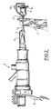
- Cylinder 1 is of the "single effect" type. Its actuating rod 3, integral with an internal piston not shown, cooperates with a clutch release fork 4, of which only the upper part appears on the diagram. Conventionally, the cylinder 1 is at rest in the engaged situation, and receives oil pressure to disengage the transmission by pulling fork 4 to the left of the figure.
- the rod 3 crosses the fork 4, and pulls on it by means of a ball joint 6 bearing on the latter.
- the ball joint 6 is immobilized on rod 3 by means of a clip adjustment 7, engaged simultaneously in a groove 8 of the ball 6, and in one of the grooves 9 formed on a bar 11 fixed to the end of the rod 3.
- Figure 1 also indicates the presence of a crimped ring 12 on the rod of the jack 1, and an indexing block 15 arranged temporarily between the cylinder body la and the ring 12, in order to correctly position the rod 3 before adjusting the patella.
- This indexing aims to guarantee the rod 3 of the jack a sufficient operating travel to the left and to the right of the diagram, to disengage, and to catch up at the end of the range the offset imposed on it by wear progressive clutch linings.
- the cylinder illustrated in FIG. 1 and in FIG. 2 can especially be used in a clutch system automatic electronically controlled, but can also be mechanically controlled.
- the adjustment device illustrated by Figure 2 has indeed a wedge 13 now temporarily the drive element 6 of the fork 4 in a waiting position on a part 11 of the rod 3, such that a bar 11 fixed to the end of the latter.
- the drive element 6, is for example, but without no obligation in the form of a ball joint, which can be move on the bar 11 to the fork 4 under the action of a spring 14 appearing more clearly in FIGS. 3A and 3B.
- the spring 14 is supported on a cup 16 fixed to the end of the bar. However, this displacement is not possible only after removal of the temporary wedging element 13.
- the bar 11 can advantageously be "at the bottom of the tree", so that element 6 can be resiliently pushed back by spring 14 against fork 4, with no possibility of return to the opposite direction.
- the spring 14 bears on the cup stop 16 and on a stop member 17 secured to the ball 6.
- the wedging element therefore temporarily holds the spring 14, and the drive ball 6 against the stop cup 16, before the spring automatically pushes back the ball joint against the fork, by sliding it on the bar in fir tree base 11.
- the measures proposed by the invention to effect this adjustment mainly consist in initially retaining the drive ball 6 away from fork 4 by means of wedge 13, before removing this wedge to leave the ball 6 automatically find on rod 3 the location in which it has no play vis-à-vis the fork 4 in situation engaged. According to the invention, this location is kept until the adjustment operation following, since the structure of the bar prevents the ball joint to move away from the fork.
- the invention therefore makes it possible to simplify the mounting of a cylinder clutch control, replacing an operation manual adjustment which requires the special attention of a operator, by a particularly reliable automatic adjustment, which allows a significant saving of time on the chain of mounting.
Landscapes
- Engineering & Computer Science (AREA)
- General Engineering & Computer Science (AREA)
- Mechanical Engineering (AREA)
- Health & Medical Sciences (AREA)
- Oral & Maxillofacial Surgery (AREA)
- Hydraulic Clutches, Magnetic Clutches, Fluid Clutches, And Fluid Joints (AREA)
- Mechanical Operated Clutches (AREA)
Applications Claiming Priority (2)
| Application Number | Priority Date | Filing Date | Title |
|---|---|---|---|
| FR9702727 | 1997-03-07 | ||
| FR9702727A FR2760412B1 (fr) | 1997-03-07 | 1997-03-07 | Procede et dispositif de reglage d'un verin de commande d'embrayage |
Publications (1)
| Publication Number | Publication Date |
|---|---|
| EP0863325A1 true EP0863325A1 (de) | 1998-09-09 |
Family
ID=9504519
Family Applications (1)
| Application Number | Title | Priority Date | Filing Date |
|---|---|---|---|
| EP98400472A Withdrawn EP0863325A1 (de) | 1997-03-07 | 1998-02-27 | Verfahren und Vorrichtung zum Einstellen eines Kupplungsbetätigungszylinders |
Country Status (2)
| Country | Link |
|---|---|
| EP (1) | EP0863325A1 (de) |
| FR (1) | FR2760412B1 (de) |
Cited By (2)
| Publication number | Priority date | Publication date | Assignee | Title |
|---|---|---|---|---|
| FR2964915A1 (fr) * | 2010-09-17 | 2012-03-23 | Peugeot Citroen Automobiles Sa | Dispositif de reglage de longueur de cable de debrayage d'un vehicule |
| FR3010948A1 (fr) * | 2013-09-26 | 2015-03-27 | Peugeot Citroen Automobiles Sa | Procede de reglage d'une commande de debrayage a cable |
Families Citing this family (1)
| Publication number | Priority date | Publication date | Assignee | Title |
|---|---|---|---|---|
| WO2006041876A1 (en) | 2004-10-06 | 2006-04-20 | Johnson Controls Technology Company | Instrument cluster with translucent or transparent sheet |
Citations (3)
| Publication number | Priority date | Publication date | Assignee | Title |
|---|---|---|---|---|
| US4854185A (en) * | 1988-10-17 | 1989-08-08 | Babcock Industries Inc. | Manually operated and locked conduit length adjuster system |
| WO1993025824A1 (en) * | 1992-06-05 | 1993-12-23 | Automotive Products Plc | A clutch actuation system and a cable therefor |
| FR2718202A1 (fr) * | 1994-03-31 | 1995-10-06 | Rockwell Bcs France | Dispositif de rattrapage de jeu automatique pour système de transmission d'effort en ligne. |
-
1997
- 1997-03-07 FR FR9702727A patent/FR2760412B1/fr not_active Expired - Fee Related
-
1998
- 1998-02-27 EP EP98400472A patent/EP0863325A1/de not_active Withdrawn
Patent Citations (3)
| Publication number | Priority date | Publication date | Assignee | Title |
|---|---|---|---|---|
| US4854185A (en) * | 1988-10-17 | 1989-08-08 | Babcock Industries Inc. | Manually operated and locked conduit length adjuster system |
| WO1993025824A1 (en) * | 1992-06-05 | 1993-12-23 | Automotive Products Plc | A clutch actuation system and a cable therefor |
| FR2718202A1 (fr) * | 1994-03-31 | 1995-10-06 | Rockwell Bcs France | Dispositif de rattrapage de jeu automatique pour système de transmission d'effort en ligne. |
Cited By (2)
| Publication number | Priority date | Publication date | Assignee | Title |
|---|---|---|---|---|
| FR2964915A1 (fr) * | 2010-09-17 | 2012-03-23 | Peugeot Citroen Automobiles Sa | Dispositif de reglage de longueur de cable de debrayage d'un vehicule |
| FR3010948A1 (fr) * | 2013-09-26 | 2015-03-27 | Peugeot Citroen Automobiles Sa | Procede de reglage d'une commande de debrayage a cable |
Also Published As
| Publication number | Publication date |
|---|---|
| FR2760412B1 (fr) | 1999-04-16 |
| FR2760412A1 (fr) | 1998-09-11 |
Similar Documents
| Publication | Publication Date | Title |
|---|---|---|
| EP0030494B1 (de) | Mechanische Steuerung durch axial verschiebbares Kabel in einem flexiblen Mantel | |
| FR2712051A1 (fr) | Embrayage à friction à compensation automatique de l'usure et transmetteurs de jeu. | |
| FR2589545A1 (fr) | Dispositif de stationnement pour une transmission automatique | |
| FR2480692A1 (fr) | Dispositif de commande pour le mecanisme a soupape d'un servofrein | |
| WO2004026653A1 (fr) | Servomoteur d'assistance pneumatique au freinage | |
| EP0863325A1 (de) | Verfahren und Vorrichtung zum Einstellen eines Kupplungsbetätigungszylinders | |
| EP0186537B1 (de) | Scheibenbremse | |
| EP0113261A1 (de) | Automatisch nachstellende Scheibenbremse | |
| EP0163566A1 (de) | Scheibenbremse mit Selbsttätiger Nachstellvorrichtung | |
| EP0037755B1 (de) | Gleitsattelscheibenbremse | |
| EP2090799B1 (de) | Trommelbremse für ein Kraftfahrzeug sowie hiermit versehenes Kraftfahrzeug | |
| EP0175600B1 (de) | Nachstellvorrichtung für Scheibenbremse | |
| EP0699844A1 (de) | Kupplungsbetätigungseinrichtung mit Nachstellvorrichtung | |
| EP0835482B1 (de) | Druckregelndes elektromagnetventil für hydraulischen kreis | |
| FR2700590A1 (fr) | Dispositif de débrayage à actionneur hydraulique à encliqueter sur un embrayage de type tiré. | |
| EP0192546B1 (de) | Hydraulischer Bremskraftverstärker | |
| EP0151070A2 (de) | Selbsttätig nachstellende Bremsbetätigungsvorrichtung | |
| EP0146444B1 (de) | Verankerung eines Verstrebungselementes, welches eine Einrichtung zur automatischen Regelung für ein Bremsbackensegment aufweist | |
| FR2492757A2 (fr) | Unite de freinage assiste pour vehicules automobiles | |
| EP0054469B1 (de) | Trommelbremse mit Bremskraftregelung | |
| EP0682613B1 (de) | Elektromagnetisch und durch druck betätigbares ventil | |
| FR2847309A1 (fr) | Systeme d'actionnement avec commande de la course | |
| FR2660268A1 (fr) | Compensateur de freinage asservi a la charge. | |
| FR3157328A1 (fr) | Système de freinage ferroviaire pour véhicule ferroviaire à freins à au moins une garniture ou à au moins une semelle | |
| FR2681116A1 (fr) | Dispositif de commande d'un frein a disque pour vehicule. |
Legal Events
| Date | Code | Title | Description |
|---|---|---|---|
| PUAI | Public reference made under article 153(3) epc to a published international application that has entered the european phase |
Free format text: ORIGINAL CODE: 0009012 |
|
| AK | Designated contracting states |
Kind code of ref document: A1 Designated state(s): BE DE |
|
| AX | Request for extension of the european patent |
Free format text: AL;LT;LV;MK;RO;SI |
|
| 17P | Request for examination filed |
Effective date: 19990304 |
|
| AKX | Designation fees paid |
Free format text: BE DE |
|
| RBV | Designated contracting states (corrected) |
Designated state(s): BE DE |
|
| 17Q | First examination report despatched |
Effective date: 20010706 |
|
| RAP1 | Party data changed (applicant data changed or rights of an application transferred) |
Owner name: RENAULT S.A.S. |
|
| GRAH | Despatch of communication of intention to grant a patent |
Free format text: ORIGINAL CODE: EPIDOS IGRA |
|
| STAA | Information on the status of an ep patent application or granted ep patent |
Free format text: STATUS: THE APPLICATION HAS BEEN WITHDRAWN |
|
| 18W | Application withdrawn |
Effective date: 20030108 |