EP0864206B1 - Procede et filtre non lineaire destines a reduire l'interference entre voies - Google Patents
Procede et filtre non lineaire destines a reduire l'interference entre voies Download PDFInfo
- Publication number
- EP0864206B1 EP0864206B1 EP96932410A EP96932410A EP0864206B1 EP 0864206 B1 EP0864206 B1 EP 0864206B1 EP 96932410 A EP96932410 A EP 96932410A EP 96932410 A EP96932410 A EP 96932410A EP 0864206 B1 EP0864206 B1 EP 0864206B1
- Authority
- EP
- European Patent Office
- Prior art keywords
- samples
- signal
- complex
- filtered
- low pass
- Prior art date
- Legal status (The legal status is an assumption and is not a legal conclusion. Google has not performed a legal analysis and makes no representation as to the accuracy of the status listed.)
- Expired - Lifetime
Links
Images

Classifications
-
- H—ELECTRICITY
- H04—ELECTRIC COMMUNICATION TECHNIQUE
- H04B—TRANSMISSION
- H04B1/00—Details of transmission systems, not covered by a single one of groups H04B3/00 - H04B13/00; Details of transmission systems not characterised by the medium used for transmission
- H04B1/06—Receivers
- H04B1/10—Means associated with receiver for limiting or suppressing noise or interference
- H04B1/12—Neutralising, balancing, or compensation arrangements
- H04B1/123—Neutralising, balancing, or compensation arrangements using adaptive balancing or compensation means
Definitions
- This invention relates to reduction of co-channel interference in communications systems.
- the invention is particularly applicable to, but is not limited to, cellular radio or wireless communications systems using frequency modulation (FM) such as AMPS (Advanced Mobile Phone System), AMPS_WD (Wide-band Data AMPS), CDPD (Cellular Digital Packet Data) systems, and TDMA (Time Division Multiple Access) systems including GSM (Global System for Mobile Communications).
- FM frequency modulation
- AMPS Advanced Mobile Phone System
- AMPS_WD Wide-band Data AMPS
- CDPD Cellular Digital Packet Data
- TDMA Time Division Multiple Access
- GSM Global System for Mobile Communications
- Co-channel interference is constituted by one or more interfering signals within the frequency band of a desired signal in a communications system, and is a key factor that limits the frequency reuse capacity of mobile communications systems.
- the CCI can not be reduced by conventional filtering techniques, because it falls within the bandwidth of the desired signal.
- One technique for reducing CCI is limiting of a received complex signal which comprises a mixture of a desired FM (frequency modulated) signal and an independent weaker (i.e. lower average power) CCI.
- the desired FM signal has a constant envelope, whereas the received signal has a non-constant envelope due to the CCI.
- the complex signal limiter converts the input mixture to a constant envelope signal, transforming at least half of the CCI energy outside the bandwidth of the desired signal so that it can be filtered out by a low pass filter.
- This technique can be supplemented by non-linear filtering of the output of the complex signal limiter, so that an average CCIC gain due to the complex signal limiter and non-linear filter (CLNF) approaches 6 dB.
- UK patent application GB-A-2 227 907 published August 8, 1990 and entitled “Improvements in or relating to interference suppressors” discloses an interference suppressor using an analog amplitude limiter whose output is supplied to a linear filter.
- "A Modified Adaptive FIR Equalizer for Multipath Echo Cancellation in FM Transmission” by K.-D. Kammeyer et al., IEEE Journal on Selected Areas in Communications, vol. SAC-5, no. 2, February 1987 discloses a linear filter and a digital limiter performing the function x(k)/
- Quadadratic Filters for Signal Processing by G.L. Sicuranza, Proceedings of the IEEE, vol. 80, no. 8, pp. 1263 to 1285, August 1992 mentions at page 1277 that non-linear polynomial filters may be suitable for adaptive equalization of channel non-linearities, non-linear equalization of digital satellite channels, and non-linear intersymbol interference cancellation.
- An object of this invention is to provide an improved method of reducing co-channel interference of a frequency modulated received signal, and a non-linear filter for use in carrying out the method, which can provide a further increase in CCIC gain.
- this invention provides a method of reducing co-channel interference of a frequency modulated received signal, having a predetermined signal bandwidth, represented by a complex signal having samples x(k) where k is an integer, comprising the steps of: amplitude limiting each sample to produce a limited sample substantially equal to x(k) /
- the limited samples are low pass filtered in accordance with the predetermined signal bandwidth to produce filtered samples, and the different derivatives are produced from the filtered samples.
- the step of producing different derivatives includes the steps of producing squared filtered samples and low pass filtering the squared filtered samples, and the steps of producing and combining the different derivatives include the step of forming a product of the low pass filtered, squared filtered samples with a complex conjugate of the filtered samples.
- the steps of producing and combining the different derivatives further include the steps of producing a product of the filtered samples with a complex conjugate of the filtered samples and removing d.c. components from the product to produce a resultant signal, and further include the steps of producing a product of the filtered samples, a constant 3, and said resultant signal, forming a difference between this product and a sum of the filtered samples and said product of the low pass filtered, squared filtered samples with the complex conjugate of the filtered samples, and low pass filtering the difference in accordance with the predetermined signal bandwidth.
- the step of low pass filtering the squared filtered samples comprises the sequential steps of up-sampling by a factor of 2, low pass filtering, and down-sampling by a factor of 2.
- the invention also provides a non-linear filter for reducing co-channel interference of a frequency modulated signal having a predetermined signal bandwidth and represented by amplitude limited complex signal samples, the non-linear filter comprising: a first signal path including complex signal processing units arranged to multiply the complex signal samples by their complex conjugates and to high pass filter the products to produce resultant signal samples from which d.c. components are removed; a second signal path including complex signal processing units arranged to produce derivative signal samples of at least one second or higher order power of the complex signal samples; and complex signal combining units arranged to combine the resultant signal samples of the first signal path, the derivative signal samples of the second signal path, and the complex signal samples to produce combined signal samples having less co-channel interference than the complex signal samples.
- the non-linear filter preferably includes a low pass filter, having a pass band corresponding to the predetermined signal bandwidth, via which the complex signal samples are supplied, and a low pass filter, having a pass band corresponding to the predetermined signal bandwidth, arranged to filter the combined signal samples to produce output signal samples of the non-linear filter.
- the complex signal processing units of the second signal path include a multiplier arranged to square the complex signal samples, a low pass filter arranged to filter the squared samples, and a multiplier arranged to multiply the filtered squared signals by the complex conjugates of the complex signal samples to produce the derivative signal samples.
- the complex signal processing units of the second signal path further include a two-times up-sampler preceding the low pass filter and a two-times down-sampler following the low pass filter.
- the complex signal processing and combining units are preferably provided as functions of a digital signal processor.
- the invention further provides apparatus for reducing co-channel interference of a frequency modulated received signal, having a predetermined signal bandwidth, represented by a complex signal having samples x(k) where k is an integer, the apparatus comprising: a complex signal limiter arranged to limit each sample to produce a limited sample substantially equal to x(k)/
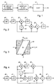
- a block diagram illustrates parts of a wireless communications receiver, in which an FM communications signal is received by an RF (radio frequency) receiver circuit and down converter 10 to produce a signal which is sampled and the samples converted into digital form by a sampler and A-D (analog-to-digital) converter 11.
- RF radio frequency
- A-D analog-to-digital
- the digital samples are supplied to a complex signal limiter and non-linear filter (CLNF) 12.
- the output of the CLNF 12 is supplied, optionally via further CCI reducing units (not shown), to an FM demodulator (not shown).
- the CCI may for example be due to frequency reuse in other cells of the system, and/or it may originate from sources external to the communications system.
- the CLNF 12 is implemented in a DSP (digital signal processor) integrated circuit, which desirably also implements other processing functions in the receiver system.
- DSP digital signal processor
- an AMPS voice channel has a bandwidth of 30 kHz and carries a constant (amplitude) envelope FM signal which comprises a voice signal with a modulation frequency in the range from 300 to 3400 Hz and a supervisory audio tone (SAT) with a modulation frequency around 6 kHz, and can also include a signalling tone (ST) with a modulation frequency of 10 kHz.
- SAT supervisory audio tone
- ST signalling tone
- the peak deviation, or range of frequency change, of these modulating signals, and of wide-band data which can also be carried by the voice channel is typically 8 kHz or less.
- the sampling rate is about 48 kHz.
- the desired AMPS signal is denoted as a complex signal A s e j ⁇ s (k) with in-phase and quadrature-phase components, where As is the amplitude and ⁇ s (k) is the phase of each sample k of the complex signal.
- the first order difference of the phase is referred to as the instantaneous frequency ⁇ ⁇ s (k), and the second order difference s (k) is referred to as the variation speed of the instantaneous frequency.
- ⁇ ⁇ s (k) ⁇ s (k) - ⁇ s (k - 1)
- s (k) ⁇ ⁇ s (k) - ⁇ ⁇ s (k - 1).
- the CLNF 12 serves as described below to improve the signal-to-interference (C/I) ratio of the sampled signal by a factor which is referred to as the CCI cancellation (CCIC) gain of the CLNF.
- C/I signal-to-interference
- CCIC CCI cancellation
- one form of the CLNF 12 comprises a complex signal limiter 20, low pass filters (LPFs) 21 and 27, a complex conjugate function 22, complex signal multipliers 23 and 25, a high pass filter (HPF) 24, and a complex signal adder 26.
- LPFs 21 and 27 provides low pass filtering of each of the real and imaginary components of the complex signal supplied to it, and has a bandwidth of 15 kHz corresponding to that of the desired signal (30 kHz, this being centered on 0 kHz for the LPF).
- the functions of the CLNF are conveniently implemented in a DSP; thus for example a single LPF function of the DSP can be used to implement both LPFs 21 and 27.
- Each LPF preferably has a short impulse response to reduce processing delay, and for example can be a Butterworth or Gaussian filter.
- the complex signal limiter 20 is supplied with an input signal x(k) which is assumed to be a mixture of a desired signal as indicated above and a weaker CCI signal having amplitude A i and phase ⁇ i (k).
- x(k) A s e j ⁇ s (k) + A i e j ⁇ i (k)
- ⁇ Ai / As (i.e. the input signal to interference ratio is 1/ ⁇ ) and assuming that the C/I ratio is high, i.e.
- the CCIC gain of the complex signal limiter 20 is enhanced by the remainder of the CLNF 12 which constitutes a non-linear filter. More particularly, the units 21 to 27 of the CLNF 12 serve to reduce the dominant or first order CCI terms in the output of the complex signal limiter 20, i.e. the second and third terms in the last equation for x lim (k) above.
- the output of the complex signal limiter 20 is filtered by the LPF 21, whose output is supplied to one input of each of the complex signal multipliers 23 and 25, to one input of the complex signal adder 26, and via the complex conjugate function 22 to a second input of the complex signal multiplier 23.
- the output of the complex signal multiplier 23 is supplied via the HPF 24, which serves to remove d.c. components and can for example be an IIR (infinite impulse response) filter having a characteristic of the form (1 - z -1 ) / (1 - 0.95 z -1 ), to a second input of the complex signal multiplier 25, whose output is supplied to a subtracting input of the complex signal adder 26.
- the output of the complex signal adder 26 is low pass filtered by the LPF 27.
- x N (k) is used to denote the output signal from the unit having the reference N.
- x 21 (k) refers to the output of the LPF 21.
- the output x 27 (k) is the same as the input x lim (k).
- the operation of the non-linear filter of the CLNF 12 as described above can be represented by a graph as shown in Fig. 3, in which the axes represent the instantaneous frequencies ⁇ ⁇ s (k) and ⁇ ⁇ i (k) of the desired signal and the interference respectively.
- each of these instantaneous frequencies can vary within the signal bandwidth ( ⁇ 15 kHz for an AMPS signal as described above), so that the instantaneous frequencies can vary within a square area 30 centered on the origin of the instantaneous frequency axes in Fig. 3.
- ⁇ B represents the signal bandwidth centered on 0 kHz
- the sides of the square area 30 intercept the axes at ⁇ B as shown in Fig. 3.
- the axes are not shown within this square area 30 in Fig. 3.
- the instantaneous frequencies ⁇ ⁇ s (k) and ⁇ ⁇ i (k) are uniformly distributed and statistically independent within the signal bandwidth, then there is an equal probability distribution for all points in the square area 30.
- case 1 above corresponds to a white area identified G1
- case 2 above corresponds to areas identified G2 and marked by horizontal lines.
- the white area G1 represents a probability P1 for case 1 discussed above for which the CCIC gain is G1
- the areas G2 represent a probability P2 for case 2 discussed above for which the CCIC gain is increased to G2.
- the present invention starts from this new understanding, and extends this by recognizing that a further improvement in CCIC gain can be achieved if the white area G1 in the graph can be reduced while still maintaining large (ideally infinite) CCIC gains in other areas of the graph outside of the white area. More particularly, the invention recognizes that more extensive processing of the limited complex signal in the non-linear filter can result in the graph of Fig. 3 being divided up into a greater number of areas, in which the white area G1 is reduced and the other areas have sufficiently high ratios of CCIC gain to probability (i.e. area) that the overall CCIC gain G given by equation (2) is enhanced.
- the present invention provides at least some forms of the CLNF 12 as described below in which a significant improvement in overall CCIC gain is provided with very little increase in processing. It is envisaged that other forms of the CLNF, which may involve higher order powers of the complex signal samples and more extensive processing, can be devised which would provide even further improvements in CCIC gain.
- FIG. 4 there is illustrated an improved form of the CLNF 12 which comprises units and functions 40 to 47 which are the same as the units and functions 20 to 27 respectively as described above with reference to Fig. 2 and are arranged in the same manner, except that the complex signal multiplier 45 is provided with an additional multiplication by a constant 3, and the complex signal adder 46 is provided with an additional summing input.
- a complex signal multiplier 48 arranged to square the output of the LPF 41, an LPF 49 arranged to low pass filter the output of the complex signal multiplier 48, and a complex signal multiplier 50 arranged to multiply the output of the LPF 49 by the complex conjugate output of the function 42, the output of this complex signal multiplier being supplied to the additional summing input of the complex signal adder 46.
- the LPF 49 has a short impulse response and a bandwidth corresponding to the signal bandwidth. However, this is twice the bandwidth of the LPFs 41 and 47, because the signal bandwidth is doubled by the squaring provided by the immediately preceding complex signal multiplier 48. While the DSP in which the CLNF 12 is implemented could include a separate LPF function for the LPF 49, this complication can be easily avoided by the modified form of the CLNF of Fig. 4 shown in Fig. 5.
- the modified form of the CLNF 12 shown in Fig. 5 is the same as that of Fig. 4, except that the LPF 49 of Fig. 4 is replaced by consecutive functions 51 to 53, and a compensating complex signal delay 54 is provided in the complex signal path from the LPF 41 to the units and functions 42, 43, 45, and 46.
- the function 51 is a two-times up-sampler or interpolation function
- the function 52 is a LPF which can be identical to the LPFs 41 and 47
- the function 53 is a two-times down-sampler or decimator.
- the combination of these functions corresponds to the double-bandwidth LPF 49 of Fig.
- the functions 51 to 53 also introduce a delay of for example two sample periods, this is compensated in the parallel paths to the output of the CLNF 12 by the delay function 54.
- Fig. 6 shows a graph which illustrates the operation of the CLNF 12 of Fig. 4 in a similar manner to the illustration in Fig. 3 of the operation of the CLNF 12 of Fig. 2.
- the CLNF 12 of Fig. 4 six cases are considered below and are represented in Fig. 6 by areas G1 to G6 within the area 60, with CCIC gains also denoted by the same references.
- the area G1 is white, the areas G2 are checked, and the areas G3 to G6 are shown respectively with wide-spaced horizontal lines, narrow-spaced horizontal lines, wide-spaced vertical lines, and narrow-spaced vertical lines.
- x 48 (k) refers to the output of the complex signal multiplier 48.
- Fig. 7 shows a graph of overall CCIC gain against the input signal to interference ratio, a line 72 representing the CCIC gain characteristic for the CLNF of Fig. 2 and a line 74 representing the CCIC gain characteristic for the CLNF of Fig. 4 or Fig. 5. It can be seen from this graph that the CLNF of Fig. 4 or Fig. 5 not only provides a significant enhancement of overall CCIC gain over that of the CLNF of Fig. 2, but it maintains its CCIC gain at lower input signal-to-interference ratios (e.g. less than 6 dB as illustrated) where the need for an enhanced CCIC gain is particularly great. Thus the CLNF of Fig. 4 or Fig. 5 provides a significant improvement over the CLNF of Fig. 2.
- step 1 a squaring (power of 2) of the limited and low pass filtered complex signal x 41 (k) in the complex signal multiplier 48 is selected, which as explained above gives rise to the boundary lines shown in Fig. 6 halving the area G1.
- step 2 and 3 signal processing functions and combinations, including the LPF 49, complex signal multiplier 50, the constant 3 applied to the complex signal multiplier 45, and the addition in the complex signal adder 46, are then determined, and an optimum result selected, in a manner which substantially completely cancels the interference components in the largest areas G5, and also in the areas G4, and enhances the CCIC gain in the other areas G2, G3, and G6.
Landscapes
- Engineering & Computer Science (AREA)
- Computer Networks & Wireless Communication (AREA)
- Signal Processing (AREA)
- Noise Elimination (AREA)
- Complex Calculations (AREA)
Claims (16)
- Procédé de réduction des interférences entre canaux d'un signal reçu modulé en fréquence, ayant une largeur de bande prédéterminée du signal, représenté par un signal complexe ayant des échantillons x(k), k étant un nombre entier, comprenant les étapes suivantes :la limitation en amplitude de chaque échantillon pour la production d'un échantillon limité qui est pratiquement égale à x(k)/|x(k)|, etle filtrage non linéaire des échantillons limités afin que la compensation des interférences entre canaux soit accrue, l'étape de filtrage non linéaire comprenant les étapes suivantes :la production de dérivées différentes des échantillons limités, les dérivées différentes comprenant une dérivée du second ordre au moins ou d'un ordre plus élevé des échantillons limités,la combinaison des dérivées différentes afin que la compensation des interférences entre canaux soit accrue dans la combinaison, etle filtrage passe-bas de l'une au moins des dérivées, des échantillons limités et de la combinaison en fonction de la largeur de bande prédéterminée du signal.
- Procédé selon la revendication 1, dans lequel les échantillons limités subissent un filtrage passe-bas selon la largeur de bande prédéterminée du signal pour la production d'échantillons filtrés, et les différentes dérivées sont produites à partir des échantillons filtrés.
- Procédé selon la revendication 2, dans lequel l'étape de production de différentes dérivées comprend une étape de production d'échantillons filtrés portés au carré.
- Procédé selon la revendication 3, dans lequel l'étape de production de différentes dérivées comprend en outre une étape de filtrage passe-bas des échantillons filtrés portés au carré.
- Procédé selon la revendication 4, dans lequel les étapes de production et de combinaison des différentes dérivées comprennent une étape de formation d'un produit des échantillons filtrés portés au carré ayant subi le filtrage passe-bas, par la valeur complexe conjuguée des échantillons filtrés.
- Procédé selon la revendication 5, dans lequel les étapes de production et de combinaison des différentes dérivées comprennent en outre des étapes de production d'un produit des échantillons filtrés avec une valeur complexe conjuguée des échantillons filtrés, et la suppression des composantes en courant continu du produit pour l'obtention d'un signal résultant.
- Procédé selon la revendication 6, dans lequel les étapes de production et de combinaison des différentes dérivées comprennent en outre des étapes de production d'un produit des échantillons filtrés, d'une constante égale à 3, et du signal résultant, de formation d'une différence entre ce produit et une somme des échantillons filtrés portés au carré et du produit des échantillons filtrés et ayant subi le filtrage passe-bas à l'aide de la conjuguée complexe des échantillons filtrés, et de filtrage passe-bas de la différence d'après la largeur de bande prédéterminée du signal.
- Procédé selon l'une quelconque des revendications 4 à 7, dans lequel l'étape de filtrage passe-bas des échantillons filtrés portés au carré comprend des étapes séquentielles d'augmentation d'échantillonnage par un facteur deux, de filtrage passe-bas et de réduction d'échantillonnage d'un facteur deux.
- Procédé selon la revendication 1, dans lequel l'étape de production de différentes dérivées comprend la production d'échantillons filtrés portés au carré.
- Filtre non linéaire destiné à réduire les interférences entre les canaux d'un signal modulé en fréquence ayant une largeur de bande prédéterminée de signal et représenté par des échantillons de signal complexe limités en amplitude, le filtre non linéaire comprenant :un premier trajet de signal qui comprend des unités de traitement de signal complexe, disposées afin qu'elles multiplient les échantillons de signal complexe par leur valeur complexe conjuguée et assurent le filtrage passe-haut des produits pour la production d'échantillons de signal résultant dont les composantes en courant continu sont supprimées,un second trajet de signal comprenant des unités de traitement de signal complexe destinées à produire des échantillons de signal de dérivée du second ordre au moins ou d'un ordre plus élevé des échantillons de signal complexe, etdes unités de combinaison de signal complexe destinées à combiner les échantillons de signal résultant du premier trajet de signal, les échantillons de signal de dérivée du second trajet de signal, et les échantillons de signal complexe pour la production d'échantillons de signal combiné ayant des interférences réduites entre les canaux par rapport aux échantillons de signal complexe.
- Filtre non linéaire selon la revendication 10, comprenant un filtre passe-bas ayant une bande passante qui correspond à une largeur de bande prédéterminée du signal et par l'intermédiaire duquel les échantillons de signal complexe sont transmis.
- Filtre non linéaire selon la revendication 11 ou 12, comprenant un filtre passe-bas, ayant une bande passante qui correspond à la largeur de bande prédéterminée du signal, et destiné à filtrer les échantillons de signal combiné pour la production d'échantillons de signal de sortie de filtre non linéaire.
- Filtre non linéaire selon la revendication 10, 11 ou 12, dans lequel les unités de traitement de signal complexe du second trajet de signal comprennent un circuit multiplicateur destiné à porter au carré les échantillons de signal complexe, un filtre passe-bas destiné à filtrer les échantillons portés au carré, et un circuit multiplicateur destiné à multiplier les signaux filtrés portés au carré par les valeurs complexes conjuguées des échantillons de signal complexe pour la production des échantillons de signal de dérivée.
- Filtre non linéaire selon la revendication 13, dans lequel les unités de traitement de signal complexe du second trajet de signal comprennent en outre un échantillonneur de multiplication par deux du nombre d'échantillons qui précède le filtre passe-bas et un échantillonneur de division par deux du nombre d'échantillons qui suit le filtre passe-bas.
- Filtre non linéaire selon l'une quelconque des revendications 10 à 14, dans lequel les unités de traitement et de combinaison de signal complexe sont des fonctions d'un processeur de signaux numériques.
- Appareil de réduction des interférences entre les canaux d'un signal reçu modulé en fréquence ayant une largeur de bande de signal prédéterminée, représenté par un signal complexe ayant des échantillons x(k), k étant un nombre entier, l'appareil comprenant :un limiteur de signal complexe destiné à limiter chaque échantillon pour la production d'un échantillon limité pratiquement égal à x(k)/|x(k)|, etun filtre non linéaire selon l'une quelconque des revendications 10 à 15 auquel sont transmis les échantillons limités sous forme d'échantillons de signal complexe.
Applications Claiming Priority (3)
| Application Number | Priority Date | Filing Date | Title |
|---|---|---|---|
| US565265 | 1995-11-30 | ||
| US08/565,265 US5778310A (en) | 1995-11-30 | 1995-11-30 | Co-channel interference reduction |
| PCT/CA1996/000675 WO1997020397A1 (fr) | 1995-11-30 | 1996-10-09 | Procede et filtre non lineaire destines a reduire l'interference entre voies |
Publications (2)
| Publication Number | Publication Date |
|---|---|
| EP0864206A1 EP0864206A1 (fr) | 1998-09-16 |
| EP0864206B1 true EP0864206B1 (fr) | 1999-12-01 |
Family
ID=24257863
Family Applications (1)
| Application Number | Title | Priority Date | Filing Date |
|---|---|---|---|
| EP96932410A Expired - Lifetime EP0864206B1 (fr) | 1995-11-30 | 1996-10-09 | Procede et filtre non lineaire destines a reduire l'interference entre voies |
Country Status (8)
| Country | Link |
|---|---|
| US (1) | US5778310A (fr) |
| EP (1) | EP0864206B1 (fr) |
| JP (1) | JP3122793B2 (fr) |
| CN (1) | CN1086866C (fr) |
| CA (1) | CA2187480C (fr) |
| DE (1) | DE69605447T2 (fr) |
| MX (1) | MX9804211A (fr) |
| WO (1) | WO1997020397A1 (fr) |
Cited By (1)
| Publication number | Priority date | Publication date | Assignee | Title |
|---|---|---|---|---|
| WO2014099022A1 (fr) * | 2012-12-18 | 2014-06-26 | Intel Corporation | Techniques permettant de gérer l'interférence dans un système de communications à canaux multiples |
Families Citing this family (24)
| Publication number | Priority date | Publication date | Assignee | Title |
|---|---|---|---|---|
| WO1998012821A1 (fr) * | 1996-09-18 | 1998-03-26 | Philips Electronics N.V. | Circuit de detection d'interferences avec discrimination definie dans le domaine amplitude-frequence |
| KR100251560B1 (ko) * | 1996-10-29 | 2000-04-15 | 윤종용 | 부호분할 다중 접속방식 단말기의 외부 간섭신호 제거장치 |
| US6097773A (en) * | 1997-05-22 | 2000-08-01 | Nortel Networks Limited | Co-channel interference reduction |
| GB9804354D0 (en) * | 1998-03-03 | 1998-04-22 | Pettigrew Archibald M | Improvements in FM demodulation circuits |
| US6271781B1 (en) * | 1998-06-10 | 2001-08-07 | Lockheed Martin Corporation | Nonlinear filter correction of multibit ΣΔ modulators |
| CN1076917C (zh) * | 1998-09-11 | 2001-12-26 | 华为技术有限公司 | 码分多址扩频无线通信系统基站的基带成形滤波器 |
| US6553214B1 (en) | 1999-05-05 | 2003-04-22 | Tenatronics Limited | Active window glass antenna system with automatic overload protection circuit |
| US6714775B1 (en) | 2000-02-24 | 2004-03-30 | Veridian Engineering, Inc. | Interference canceller |
| US6714774B1 (en) * | 2000-02-24 | 2004-03-30 | Texas Instruments Incorporated | Antenna reception diversity in wireless communications |
| EP1138771A1 (fr) | 2000-03-30 | 2001-10-04 | Societe Des Produits Nestle S.A. | Endo-Mannanase de café |
| US6373418B1 (en) * | 2000-05-25 | 2002-04-16 | Rockwell Collins, Inc. | Nyquist response restoring delta-sigma modulator based analog to digital and digital to analog conversion |
| US6560440B1 (en) | 2000-10-10 | 2003-05-06 | General Dynamics Decision Systems, Inc. | Method for precompensating frequency data for use in high-velocity satellite communication systems |
| CN101072018B (zh) * | 2006-05-12 | 2010-06-09 | 扬智科技股份有限公司 | 数字信号的分频滤波方法及其系统 |
| US20080063122A1 (en) * | 2006-09-07 | 2008-03-13 | Gwo-Jia Jong | Method for suppressing co-channel interference from different frequency |
| US7904047B2 (en) * | 2007-10-31 | 2011-03-08 | Broadcom Corporation | Radio frequency filtering technique with auto calibrated stop-band rejection |
| US8849227B2 (en) | 2009-09-28 | 2014-09-30 | The Trustees Of Columbia University In The City Of New York | Systems and methods for controlling the second order intercept point of receivers |
| US8594603B2 (en) * | 2009-11-08 | 2013-11-26 | The Trustees Of Columbia University In The City Of New York | Systems and methods for cancelling interferers in a receiver |
| CN101944892B (zh) * | 2010-08-12 | 2013-11-06 | 聚辰半导体(上海)有限公司 | 一种低成本有效迭代多阶数字滤波方法及装置 |
| CN102420621B (zh) * | 2011-11-16 | 2014-10-08 | 北京华力创通科技股份有限公司 | 对数字信号的带外干扰进行抑制的方法和装置 |
| CN105929684A (zh) * | 2016-06-22 | 2016-09-07 | 广东电网有限责任公司电力科学研究院 | 一种获取过程信号的近似降价信号的方法及装置 |
| CN105978521A (zh) * | 2016-06-22 | 2016-09-28 | 广东电网有限责任公司电力科学研究院 | 一种过程信号的近似微分信号提取方法及装置 |
| US10608685B2 (en) * | 2016-10-28 | 2020-03-31 | Perspecta Labs Inc. | Photonics based interference mitigation |
| CN108257238B (zh) * | 2018-02-13 | 2020-07-10 | 深圳市金溢科技股份有限公司 | 一种电子不停车收费设备及其射频前端和射频接收方法 |
| WO2021167905A1 (fr) * | 2020-02-17 | 2021-08-26 | Sam Belkin | Filtre radiofréquence accordable dynamiquement et applications |
Family Cites Families (3)
| Publication number | Priority date | Publication date | Assignee | Title |
|---|---|---|---|---|
| GB2227907B (en) * | 1979-12-01 | 1990-11-14 | Plessey Co Ltd | Improvements now relating to interference suppressors |
| US5355533A (en) * | 1991-12-11 | 1994-10-11 | Xetron Corporation | Method and circuit for radio frequency signal detection and interference suppression |
| US5452015A (en) * | 1994-02-10 | 1995-09-19 | Philips Electronics North America Corporation | Method and apparatus for combating co-channel NTSC interference for digital TV transmission |
-
1995
- 1995-11-30 US US08/565,265 patent/US5778310A/en not_active Expired - Lifetime
-
1996
- 1996-10-09 JP JP09520021A patent/JP3122793B2/ja not_active Expired - Fee Related
- 1996-10-09 EP EP96932410A patent/EP0864206B1/fr not_active Expired - Lifetime
- 1996-10-09 DE DE69605447T patent/DE69605447T2/de not_active Expired - Fee Related
- 1996-10-09 CN CN96199699A patent/CN1086866C/zh not_active Expired - Fee Related
- 1996-10-09 WO PCT/CA1996/000675 patent/WO1997020397A1/fr not_active Ceased
- 1996-10-09 CA CA002187480A patent/CA2187480C/fr not_active Expired - Fee Related
-
1998
- 1998-05-27 MX MX9804211A patent/MX9804211A/es unknown
Cited By (1)
| Publication number | Priority date | Publication date | Assignee | Title |
|---|---|---|---|---|
| WO2014099022A1 (fr) * | 2012-12-18 | 2014-06-26 | Intel Corporation | Techniques permettant de gérer l'interférence dans un système de communications à canaux multiples |
Also Published As
| Publication number | Publication date |
|---|---|
| DE69605447T2 (de) | 2000-04-13 |
| US5778310A (en) | 1998-07-07 |
| JP3122793B2 (ja) | 2001-01-09 |
| CA2187480C (fr) | 2001-03-20 |
| CN1086866C (zh) | 2002-06-26 |
| CN1207836A (zh) | 1999-02-10 |
| JPH11500888A (ja) | 1999-01-19 |
| MX9804211A (es) | 1998-10-31 |
| WO1997020397A1 (fr) | 1997-06-05 |
| DE69605447D1 (de) | 2000-01-05 |
| EP0864206A1 (fr) | 1998-09-16 |
| CA2187480A1 (fr) | 1997-05-31 |
Similar Documents
| Publication | Publication Date | Title |
|---|---|---|
| EP0864206B1 (fr) | Procede et filtre non lineaire destines a reduire l'interference entre voies | |
| EP0855109B1 (fr) | Reduction d'interference entre voies | |
| US9106298B2 (en) | Suppression of adjacent channel interference by adaptive channel filtering in mobile radio receivers | |
| US5638403A (en) | Low-splatter peak-to-average signal reduction with interpolation | |
| US7466966B2 (en) | Method for clipping a wideband radio signal and corresponding transmitter | |
| US6993311B2 (en) | Radio receiver having an adaptive equalizer and method therefor | |
| US8374564B2 (en) | Signal filtering system and related methods | |
| EP1249979A2 (fr) | Processeur d'entrée et procédé de compensation de distorsion non-linéaire | |
| JPH08510892A (ja) | 直角位相受信機における自動利得制御およびdcオフセット消去のための方法および装置 | |
| KR20000052914A (ko) | 전송방법 및 그 방법의 실행을 위한 장치 | |
| US4631489A (en) | FM signal magnitude quantizer and demodulator compatible with digital signal processing | |
| US7039093B2 (en) | Arrangement for adaptive baseband filter selection | |
| US6768441B2 (en) | Methods of receiving communications signals including a plurality of digital filters having different bandwidths and related receivers | |
| US5600676A (en) | Modulation scheme with low envelope variation for mobile radio by constraining a maximum modulus of a differential phase angle | |
| EP0782259B1 (fr) | Filtre numérique à bande passante étroite | |
| US7254122B2 (en) | Apparatus and method for generating pilot beacon signal in base stations of CDMA system | |
| US6977978B1 (en) | Adaptive channel filtration for communications systems | |
| US5610950A (en) | Communication device with reduced sensitivity to in-channel interference | |
| US20030219079A1 (en) | Data transmission method and arrangement | |
| EP1555769B1 (fr) | Système de traitement de la signalisation de spectre plat | |
| US20080169871A1 (en) | Method and device for the filtering and analogue/digital conversion of analogue signal | |
| Korn | Narrowband M‐ary DPSK‐DPD with L‐diversity maximum ratio combining in Rician fading channels | |
| Kitano et al. | A narrowband interference rejection technique for DS‐CDMA system | |
| JPH0479427A (ja) | ダイバーシティ受信機 | |
| JPH09321543A (ja) | キャリア再生回路及び該キャリア再生回路を用いた復調回路 |
Legal Events
| Date | Code | Title | Description |
|---|---|---|---|
| PUAI | Public reference made under article 153(3) epc to a published international application that has entered the european phase |
Free format text: ORIGINAL CODE: 0009012 |
|
| 17P | Request for examination filed |
Effective date: 19980630 |
|
| AK | Designated contracting states |
Kind code of ref document: A1 Designated state(s): DE FR GB |
|
| GRAG | Despatch of communication of intention to grant |
Free format text: ORIGINAL CODE: EPIDOS AGRA |
|
| 17Q | First examination report despatched |
Effective date: 19990115 |
|
| GRAG | Despatch of communication of intention to grant |
Free format text: ORIGINAL CODE: EPIDOS AGRA |
|
| GRAH | Despatch of communication of intention to grant a patent |
Free format text: ORIGINAL CODE: EPIDOS IGRA |
|
| RAP3 | Party data changed (applicant data changed or rights of an application transferred) |
Owner name: NORTEL NETWORKS CORPORATION |
|
| GRAH | Despatch of communication of intention to grant a patent |
Free format text: ORIGINAL CODE: EPIDOS IGRA |
|
| GRAA | (expected) grant |
Free format text: ORIGINAL CODE: 0009210 |
|
| AK | Designated contracting states |
Kind code of ref document: B1 Designated state(s): DE FR GB |
|
| ET | Fr: translation filed | ||
| REF | Corresponds to: |
Ref document number: 69605447 Country of ref document: DE Date of ref document: 20000105 |
|
| RAP2 | Party data changed (patent owner data changed or rights of a patent transferred) |
Owner name: NORTEL NETWORKS LIMITED |
|
| PLBE | No opposition filed within time limit |
Free format text: ORIGINAL CODE: 0009261 |
|
| STAA | Information on the status of an ep patent application or granted ep patent |
Free format text: STATUS: NO OPPOSITION FILED WITHIN TIME LIMIT |
|
| 26N | No opposition filed | ||
| REG | Reference to a national code |
Ref country code: GB Ref legal event code: IF02 |
|
| REG | Reference to a national code |
Ref country code: FR Ref legal event code: CD |
|
| PGFP | Annual fee paid to national office [announced via postgrant information from national office to epo] |
Ref country code: GB Payment date: 20060915 Year of fee payment: 11 |
|
| PGFP | Annual fee paid to national office [announced via postgrant information from national office to epo] |
Ref country code: DE Payment date: 20061031 Year of fee payment: 11 |
|
| GBPC | Gb: european patent ceased through non-payment of renewal fee |
Effective date: 20071009 |
|
| PG25 | Lapsed in a contracting state [announced via postgrant information from national office to epo] |
Ref country code: DE Free format text: LAPSE BECAUSE OF NON-PAYMENT OF DUE FEES Effective date: 20080501 |
|
| REG | Reference to a national code |
Ref country code: FR Ref legal event code: ST Effective date: 20080630 |
|
| PGFP | Annual fee paid to national office [announced via postgrant information from national office to epo] |
Ref country code: FR Payment date: 20061003 Year of fee payment: 11 |
|
| PG25 | Lapsed in a contracting state [announced via postgrant information from national office to epo] |
Ref country code: GB Free format text: LAPSE BECAUSE OF NON-PAYMENT OF DUE FEES Effective date: 20071009 |
|
| PG25 | Lapsed in a contracting state [announced via postgrant information from national office to epo] |
Ref country code: FR Free format text: LAPSE BECAUSE OF NON-PAYMENT OF DUE FEES Effective date: 20071031 |