EP0864482A2 - Gerät zur Geschwindigkeitsänderung eines Fahrzeugvorderrades - Google Patents
Gerät zur Geschwindigkeitsänderung eines Fahrzeugvorderrades Download PDFInfo
- Publication number
- EP0864482A2 EP0864482A2 EP98301795A EP98301795A EP0864482A2 EP 0864482 A2 EP0864482 A2 EP 0864482A2 EP 98301795 A EP98301795 A EP 98301795A EP 98301795 A EP98301795 A EP 98301795A EP 0864482 A2 EP0864482 A2 EP 0864482A2
- Authority
- EP
- European Patent Office
- Prior art keywords
- valve
- line
- hydraulic motor
- drive
- motor
- Prior art date
- Legal status (The legal status is an assumption and is not a legal conclusion. Google has not performed a legal analysis and makes no representation as to the accuracy of the status listed.)
- Withdrawn
Links
Images



Classifications
-
- B—PERFORMING OPERATIONS; TRANSPORTING
- B60—VEHICLES IN GENERAL
- B60K—ARRANGEMENT OR MOUNTING OF PROPULSION UNITS OR OF TRANSMISSIONS IN VEHICLES; ARRANGEMENT OR MOUNTING OF PLURAL DIVERSE PRIME-MOVERS IN VEHICLES; AUXILIARY DRIVES FOR VEHICLES; INSTRUMENTATION OR DASHBOARDS FOR VEHICLES; ARRANGEMENTS IN CONNECTION WITH COOLING, AIR INTAKE, GAS EXHAUST OR FUEL SUPPLY OF PROPULSION UNITS IN VEHICLES
- B60K6/00—Arrangement or mounting of plural diverse prime-movers for mutual or common propulsion, e.g. hybrid propulsion systems comprising electric motors and internal combustion engines
- B60K6/08—Prime-movers comprising combustion engines and mechanical or fluid energy storing means
-
- B—PERFORMING OPERATIONS; TRANSPORTING
- B60—VEHICLES IN GENERAL
- B60K—ARRANGEMENT OR MOUNTING OF PROPULSION UNITS OR OF TRANSMISSIONS IN VEHICLES; ARRANGEMENT OR MOUNTING OF PLURAL DIVERSE PRIME-MOVERS IN VEHICLES; AUXILIARY DRIVES FOR VEHICLES; INSTRUMENTATION OR DASHBOARDS FOR VEHICLES; ARRANGEMENTS IN CONNECTION WITH COOLING, AIR INTAKE, GAS EXHAUST OR FUEL SUPPLY OF PROPULSION UNITS IN VEHICLES
- B60K17/00—Arrangement or mounting of transmissions in vehicles
- B60K17/04—Arrangement or mounting of transmissions in vehicles characterised by arrangement, location or kind of gearing
- B60K17/10—Arrangement or mounting of transmissions in vehicles characterised by arrangement, location or kind of gearing of fluid gearing
-
- B—PERFORMING OPERATIONS; TRANSPORTING
- B60—VEHICLES IN GENERAL
- B60K—ARRANGEMENT OR MOUNTING OF PROPULSION UNITS OR OF TRANSMISSIONS IN VEHICLES; ARRANGEMENT OR MOUNTING OF PLURAL DIVERSE PRIME-MOVERS IN VEHICLES; AUXILIARY DRIVES FOR VEHICLES; INSTRUMENTATION OR DASHBOARDS FOR VEHICLES; ARRANGEMENTS IN CONNECTION WITH COOLING, AIR INTAKE, GAS EXHAUST OR FUEL SUPPLY OF PROPULSION UNITS IN VEHICLES
- B60K17/00—Arrangement or mounting of transmissions in vehicles
- B60K17/34—Arrangement or mounting of transmissions in vehicles for driving both front and rear wheels, e.g. four wheel drive vehicles
- B60K17/356—Arrangement or mounting of transmissions in vehicles for driving both front and rear wheels, e.g. four wheel drive vehicles having fluid or electric motor, for driving one or more wheels
-
- B—PERFORMING OPERATIONS; TRANSPORTING
- B60—VEHICLES IN GENERAL
- B60K—ARRANGEMENT OR MOUNTING OF PROPULSION UNITS OR OF TRANSMISSIONS IN VEHICLES; ARRANGEMENT OR MOUNTING OF PLURAL DIVERSE PRIME-MOVERS IN VEHICLES; AUXILIARY DRIVES FOR VEHICLES; INSTRUMENTATION OR DASHBOARDS FOR VEHICLES; ARRANGEMENTS IN CONNECTION WITH COOLING, AIR INTAKE, GAS EXHAUST OR FUEL SUPPLY OF PROPULSION UNITS IN VEHICLES
- B60K23/00—Arrangement or mounting of control devices for vehicle transmissions, or parts thereof, not otherwise provided for
- B60K23/08—Arrangement or mounting of control devices for vehicle transmissions, or parts thereof, not otherwise provided for for changing number of driven wheels, for switching from driving one axle to driving two or more axles
-
- B—PERFORMING OPERATIONS; TRANSPORTING
- B60—VEHICLES IN GENERAL
- B60W—CONJOINT CONTROL OF VEHICLE SUB-UNITS OF DIFFERENT TYPE OR DIFFERENT FUNCTION; CONTROL SYSTEMS SPECIALLY ADAPTED FOR HYBRID VEHICLES; ROAD VEHICLE DRIVE CONTROL SYSTEMS FOR PURPOSES NOT RELATED TO THE CONTROL OF A PARTICULAR SUB-UNIT
- B60W30/00—Purposes of road vehicle drive control systems not related to the control of a particular sub-unit, e.g. of systems using conjoint control of vehicle sub-units
- B60W30/18—Propelling the vehicle
- B60W30/18009—Propelling the vehicle related to particular drive situations
- B60W30/18145—Cornering
-
- B—PERFORMING OPERATIONS; TRANSPORTING
- B62—LAND VEHICLES FOR TRAVELLING OTHERWISE THAN ON RAILS
- B62D—MOTOR VEHICLES; TRAILERS
- B62D9/00—Steering deflectable wheels not otherwise provided for
-
- B—PERFORMING OPERATIONS; TRANSPORTING
- B60—VEHICLES IN GENERAL
- B60W—CONJOINT CONTROL OF VEHICLE SUB-UNITS OF DIFFERENT TYPE OR DIFFERENT FUNCTION; CONTROL SYSTEMS SPECIALLY ADAPTED FOR HYBRID VEHICLES; ROAD VEHICLE DRIVE CONTROL SYSTEMS FOR PURPOSES NOT RELATED TO THE CONTROL OF A PARTICULAR SUB-UNIT
- B60W2540/00—Input parameters relating to occupants
- B60W2540/18—Steering angle
-
- B—PERFORMING OPERATIONS; TRANSPORTING
- B60—VEHICLES IN GENERAL
- B60Y—INDEXING SCHEME RELATING TO ASPECTS CROSS-CUTTING VEHICLE TECHNOLOGY
- B60Y2200/00—Type of vehicle
- B60Y2200/20—Off-Road Vehicles
- B60Y2200/22—Agricultural vehicles
- B60Y2200/221—Tractors
Definitions
- the present invention relates to the adjustment of the relative driven speed of the front and rear wheels of a front wheel steer vehicle when turning a corner.
- the invention has particular application in four wheel drive agricultural tractors.
- bi speed facilities will have only one "bi speed ratio" and this will determine how aggressive the bi speed facility is.
- a high ratio will cause the vehicle to jerk on turning a sharp corner, involving considerable wheelslip and an uncomfortable ride but assisting the making of a tight turn.
- This type of bi speed tends to be used in agricultural tractors for use in paddy fields. A smaller ratio will make for a smoother ride and less wheel spin and this might be used for example in a tractor for use in more conventional field work. Different operators will also have preferences for different degrees of aggressiveness.
- front wheel speed change apparatus for a vehicle having a mechanical main transmission, the apparatus comprising a hydraulic motor and means for automatically engaging drive from the hydraulic motor to the front wheels when the steering angle of the front wheels exceeds a first predetermined value.
- hydraulic drive over a mechanical one is that the ratio can be infinitely variable and, provided the torque to the front wheels does not exceed that at which the wheels will slip, the speed of the wheels will be determined solely by the steering geometry with the hydraulic drive simply providing some torque.
- the hydraulic drive may be arranged to provide sufficient torque to cause wheelslip, in which case the hydraulic drive can be arranged to provide a given front wheel speed, which may or may not be variable dependent on factors such as steering angle, vehicle speed, engine speed, main transmission ratio, etc.
- a further advantage of hydraulic drive is that, since the ratio can be varied easily, the drive can be engaged at a much smaller steering angle than a conventional bi-speed.
- a conventional bi-speed's fixed ratio will be appropriate for a given large steering angle of say 40 degrees, but will cause excessive wheel spin if drive is engaged at a smaller steering angle.
- a tractor driveline comprises an engine 1, main transmission 2, rear axle 3 and rear wheels 4.
- a front pto drive shaft 5 extends from the forward end of the engine. Extending forwardly from the main transmission 2 is a front axle drive shaft 7, and a four wheel drive clutch 8 is provided to control the engagement of conventional drive to the front axle 9 via a front differential 10.
- the front axle drive shaft 7 would normally run underneath the mounting for the engine 1, but is shown here to one side for clarity.
- a variable displacement hydraulic pump 6 is mounted in front of the engine 1 and is driven from the front pto shaft 5.
- a hydraulic motor 11 powered via a hydraulic line 12 from the pump 6.
- the output shaft 13 from the hydraulic motor 11 drives simple gearing 15 secured to the engine mounting.
- the output from the gearing 15 is connected to the front axle drive shaft 7 via a sprag clutch 14 forwardly of the four wheel drive clutch 8.
- An output 23 from the control unit 22 goes to an actuator 24 controlling the four wheel drive clutch 8.
- a further output 25 goes to an on/off control valve 26 in the hydraulic supply 12 to the motor 11.
- the steering angle may be sensed from the position of the steering cylinder and there could be a simple mechanical linkage to the four wheel drive clutch.
- the control unit 22 also receives inputs from sensors in the main transmission 2 sensing the status of the main clutch (on line 40) and the main transmission ratio (on line 39).
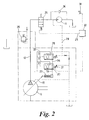
- the pump 6 is a variable displacement hydraulic pump of well known design in which the capacity is varied by varying the angle of a swashplate 18 by means of a "spring on, pressure off" control arrangement which includes a hydraulic control cylinder 27, supplied by a hydraulic line 19. Two valves 20, 28 control the pressure in the line 19 to the control cylinder 27 as described below.
- the valves 20, 28 are of simple two position design spring biased to the left position as shown in Figure 2.
- the pressure in the supply line 12 from the pump ("supply pressure") is applied to the left hand side (in Figure 2) of the valve members of both valves 20, 28 via lines 30, 31 respectively.
- Branch lines 32, 33 from the supply line 12 also lead to the inlets of the valves 20, 28 respectively.
- the on/off valve 26 is shown at the top of Figure 2. As previously described, the valve 26 is situated in the supply line 12 from the pump 6 to the motor 11 and is actuated by an electronic signal from the control unit 22 to either open or shut off the supply to the motor 11.
- a line 29 leads from the motor side of the valve 26 down to the valve 28 and is arranged so that the pressure in the line 29 is applied to the right hand side (in Figure 2) of the valve member of the valve 28.
- valve 28 in its left hand position, the position drawn in Figure 2 into which it is biased, simply blocks the line 33 connecting the supply line 12 to the valve inlet.
- line 33 In its right hand position the line 33 is connected to a line 34 connecting the outlet of the valve 28 with the inlet of the valve 20, thereby supplying supply pressure to the valve 20 inlet.
- valve 20 in its left hand position again blocks the line 32 carrying supply pressure, but allows pressure in the connecting line 34 to be supplied to the control cylinder 27 via the line 19.
- the valve 20 supplies supply pressure to the control cylinder 27 via the line 19.
- the valves 20, 28 are both spring biased into the left hand position as shown in Figure 2.
- the strength of each of the springs may be varied, and the strength of the spring 37 in the valve 20 may be adjusted via the control unit 22 which has an input from a cab mounted control 38 for that purpose.
- a safety relief valve 35 is incorporated in the supply line 12 to ensure that the pump is not overloaded and a check valve 36 is connected in parallel with the motor 11 to prevent the motor working in reverse.
- the control valve 20 has supply pressure on the line 30 acting to move its valve member to the right and a variable strength spring 37 biasing it to the left. If the supply pressure is weaker, the valve will be in the left hand position (in Figure 2) and the line 32 carrying supply pressure to the inlet of the valve 20 will be blocked. There will thus be no pressure transmitted to the control cylinder 27 and the pump swashplate 18 will go to its fully open position, increasing the supply pressure and thus overcoming the spring in the valve 20 and moving it to the right. This connects the inlet of the valve 20, and thus the line 32 carrying supply pressure, to the line 19 and thus to the control cylinder 27, closing off the pump swashplate 18 and reducing the supply pressure. A loop is thus set up, with the supply pressure (in this mode "system pressure") set by the strength of the spring 37. The strength of the spring 37 may be varied by cab mounted control 38 to control the pressure to the motor 11 and thereby the maximum torque available.
- valve 26 When the valve 26 is closed, there will be substantially zero pressure on the line 29 and thus no pressure acting on the right hand side of the valve member of the valve 28.
- the spring in the valve 28 is relatively weak and its bias easily overcome by the supply pressure in the line 31 acting on the left hand side of the valve m.ember when the pump 6 is in its default maximum displacement setting.
- the valve member will thus move to the right (in Figure 2), causing supply pressure to be applied to the control cylinder which thus closes off the pump swashplate 18 thereby reducing the pump flow and hence the supply pressure.
- a loop is thus set up, with the strength of the spring in the valve 28 setting the supply pressure. This is a "standby" pressure setting with the pump doing virtually no work and just “ticking over” whilst the motor 11 is disconnected.
- the spring in the other control valve 20 is stronger than the spring in the valve 28.
- the valve 20 When there is no pressure on the line 29, therefore, the valve 20 will always be in the left hand position as shown in Figure 2 because the valve 28 will have set the supply pressure (acting on the left hand side of the valve 20) at a low "standby" level which is unable to overcome the bias of the spring 37 in the valve 20.
- the level of the "standby pressure" can be set by varying the strength of the spring in the valve 28 as schematically shown in Figure 2. In practice this will not be adjusted regularly, however.
- control of the system pressure (and thus the torque capacity of the motor 11) is purely hydraulic and responds only to the setting of the cab mounted pressure control 38.
- control cylinder 27 could alternatively be supplied from a variable valve whose setting is controlled electronically.
- the system pressure could be automatically controlled on the basis of a number of factors such as speed, engine revs., main transmission gear ratio, etc.
- the hydraulic motor 11 In normal operation of the tractor, ie driving in a straight line or making relatively gentle turns, the hydraulic motor 11 is idle and thus, whether four wheel drive is engaged or not, the front axle drive shaft 7 will be rotating faster than the sprag clutch 14 (which is not being driven) and the sprag clutch will therefore slip.
- the electronic control unit 22 When a steering angle of 15 degrees is exceeded, the electronic control unit 22 will detect this from the signals from the steering angle sensors 21. At this point the unit 22 will send a signal to the four wheel drive clutch actuator 24 to disengage the four wheel drive clutch 8 and a signal to the main solenoid valve 26 to open up flow to the motor 11. Drive from the main transmission is thus disconnected from the front axle drive shaft and the speed of rotation of the front axle drive shaft is then determined by ground speed or by the drive from the motor 11 as explained below.
- the hydraulic pump/motor In its "no load" condition the hydraulic pump/motor will drive the sprag clutch at a given maximum speed .
- the clutch will slip and no torque will be applied to the shaft.
- the sprag clutch will engage and torque will be applied to the shaft. In practice this means that the front axle will not be accelerated when cornering fast. This is generally desirable since there is no need for four wheel drive when cornering fast and it is safer not to have the hydraulic drive engaging at high speeds.
- the torque applied to the front wheels is infinitely variable by means of the control valve 20. It will be appreciated that, once the limiting position of the valve for avoiding wheel slip is found, the position of the valve may still be varied within that limit to control the torque applied to the front wheels and thus the general "aggressiveness" of the drive to the front wheels.
- This arrangement also differs from a conventional bi speed in that the drive from the engine 1 to the hydrostatic pump/motor is direct and thus the range of ratios would need to be very large if the bi speed were to operate over the entire ground speed range of the tractor. For this reason the operation of the bi speed is restricted so that it only engages when the main transmission is in a certain range of ratios.
- the transmission has 12 forward ratios selected by a three position "range” lever and a four position "gear” lever.
- the control unit 22 will only energise the motor 11 when "low” or “medium” range is engaged, corresponding to ratios 1 to 8 (a speed range of 0 - 12 kph).
- the control unit 22 includes an input on line 40 from a sensor on the main clutch and disables the motor 11 when the clutch is disengaged.
- the unit 22 will also disable the motor 11 if the signal on line 39 from the main transmission ratio sensing means indicates that the main transmission is in neutral.
- a possible variant of the system described above might be electronically to control the pump to provide front wheel speed of a given percentage of rear wheel speed, the percentage being variable with sensed steering angle.
- Another variant might be to use a fixed displacement pump driven direct from the rear wheel drive shaft.
- the steering angle is sensed in a different way, based on the displacement of the steering cylinder 154.
- a rod 157 of stainless steel or other non-magnetic material is fixed to each end of the piston of the steering cylinder, so that it moves with it.
- Mounted on or incorporated in the rod 157 are two magnets 158.
- On one side of the rod 157 is a reed switch 156 and, opposite the reed switch on the other side of the rod 157 is a piece of ferrous material 155.
- the magnets 158 on the rod 157 are so positioned that one or other of them will pass between the reed switch and the piece of ferrous material 155 when a given steering angle is reached, thereby causing the reed switch to close (or open) and send a signal to the control unit 122.
- the magnets 158 are movably mounted on the rod 157 to allow for adjustment of the steering angle at which the hydraulic drive cuts in. It will be appreciated that additional magnets could be provided to give eg a second signal at a second steering angle if necessary.
- One possibility would be to use different strength magnets and two or more reed switches which require different strengths of magnetic field to activate them.
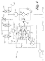
- FIG 3 the hydraulic control between the pump 6 and motor 11 is shown schematically as box 152 with control line 125 extending between it and the electronic control unit 122.
- Line 125 in fact represents a number of control lines to solenoid valves within the hydraulic system 152, and these will be explained below with reference to Figures 4 to 6.
- Figure 3 shows the main clutch 150, with an associated sensor 151 connected to the control unit 122 via a clutch status line C.
- the four-wheel drive clutch actuator 24 is connected to the control unit 122 via a four-wheel drive control line 4WD.
- a signal indicating whether the transmission is in low, medium or high range or neutral is carried on line LMHN from a sensor in the transmission to the control unit 122, whilst a signal indicative of whether the transmission is in forward or reverse is carried on line R from another sensor in the transmission to the control unit 122.
- a handbrake 159 is provided with a handbrake status sensor 160 and a handbrake status signal line H extends from the sensor to the control unit 122.
- the hydraulic system 152 (together with pump 6 and motor 11) is similar in many respects to that of the first embodiment.
- the swashplate 18 of the variable displacement pump 6 is controlled, as in the first embodiment, by a "spring on pressure off" control cylinder 27.
- the hydraulic supply line 19 to the control cylinder is connected to a valve 120, similar in most respects to the equivalent valve 20 in the first embodiment, other
- the hydraulic system 152 (together with pump 6 and motor 11) is similar in many respects to that of the first embodiment.
- the swashplate 18 of the variable displacement pump 6 is controlled, as in the first embodiment, by a "spring on pressure off' control cylinder 27.
- the hydraulic supply line 19 to the control cylinder is connected to a valve 120, similar in most respects to the equivalent valve 20 in the first embodiment, other than that the biasing spring 137, whilst still being adjustable, is not used to adjust routinely the system pressure and thus the torque provided by motor 11.
- a line 134 extends between valve 120 and valve 128, the equivalent of valve 28 in the first embodiment.
- Valve 128 is similar to valve 28 in the first embodiment - the biasing spring is adjustable, but this is only used to adjust the "stand-by" pressure, usually on a one-off basis. Unlike the first embodiment, this valve is involved in setting the pressure or volume of flow to the motor, as will be explained below.
- Lines 130, 131, 132 and 133 are branch lines from the main line 112 from the pump to the motor 11.
- a line 129 provides a supply of control pressure to the control input of valve 128 and, as with the first embodiment, the line 129 extends from line 112 between an on/off solenoid valve 126 (equivalent to valve 26 in the first embodiment) and the motor 11.
- an additional valve 139 is incorporated on a branch leading from the motor supply 112 to the tank 140 (zero pressure).
- This valve 139 is arranged to be open when valve 126 is closed and vice versa, and its function is to prevent the operation by motor 11 as a pump when the transmission is operating in reverse by providing a line directly from the motor 11 to the tank 140 when the hydrostatic drive to the front axle is switched off.
- a shunt line 143 to the hydraulic supply line 112 is provided, incorporating a variable restriction 142.
- the shunt line 143 extends around a further solenoid valve 141 in the main supply line 112. The purpose of this arrangement is to provide a system setting with a reduced maximum flow rate to the motor 11, and thus reduced maximum speed of the motor.
- valve 141 When valve 141 is open, the system operates substantially as previously described in relation to the first embodiment.
- the valve 141 When the valve 141 is closed, the flow to the motor 11 is forced to pass through the restriction 142.
- the restriction will allow fluid to pass through it at up to a given rate before it substantially affects the flow.
- a pressure drop At the critical flow rate, a pressure drop will begin to develop across the restriction 142.
- This pressure drop across the restriction 142 results in a lowering of the pressure on control pressure line 129 with respect to the pressure at the pump outlet, which means that there will be the same pressure drop across the control ports of the valve 128.
- valve member will move to the right (in Figure 2) and supply pump outlet pressure to the control cylinder via valve 120 and lines 34 and 19, which will in turn cause the swashplate to close off and reduce the flow rate to the motor via the restriction 142.
- the reduction in flow rate from the pump will, in turn, reduce or eliminate the pressure drop across the restriction 142 resulting in the pressure on each side of valve 128 equalising.
- a control loop is thus set up, with the steady state flow rate to the motor 11 being set by the strength of the valve spring in valve 128 together with the dimensions of the restriction 142.
- the diameter of the restriction 142 is in fact variable, but it is not intended that regular adjustment be made. The reasons for this being desirable will be explained later.
- the restriction 142 is adjustable and the reduction in maximum motor speed when the valve 141 is closed can therefore be set at will, although it is not a cab control and in practice will only be set once.
- valve spring 137 of valve 120 although adjustable, is not intended to be adjusted regularly as in the first embodiment. Instead the maximum pressure to the motor 11 (and thus torque provided by the motor) may be set by adjusting a limiting valve 147 connected to the control pressure line 129 and to the tank 140. The valve 147 is controlled from the tractor cab to provide the operator with adjustable maximum torque to the front wheels when the hydrostatic drive is engaged.
- a filter is provided between the motor 11 and the tank 140 to filter out particulates in the hydraulic fluid, and a system of branch lines and one-way valves 145 is provided to prevent the motor "sucking back" collected particulates when the main transmission is in reverse and the motor 11 is tending to operate as a pump.
- a filter overload valve 146 is provided in a branch line around the filter to prevent overload of the filter when the hydraulic fluid is cold or if the filter becomes blocked.
- the electronic control unit 122 is shown schematically with inputs on the left and outputs on the right.
- the inputs are: input 159 from the steering angle sensor, input LMHN from the transmission range/neutral sensor, input H from the handbrake status sensor, input C from the clutch status sensor, input R from the forward/reverse transmission status sensor and input 160 from the cab mounted on/off switch for the system.
- the outputs are: line 161 to a solenoid controlling valve 126 (see Figure 4), line 162 to a solenoid controlling valve 139 (see Figure 4), line 163 to a solenoid controlling valve 141 (see Figure 4) and output 4WD to a solenoid controlling the four-wheel drive clutch actuator 24 (see Figure 3).
- the hydrostatic front wheel speed change apparatus will be disabled, that is to say, the outputs to valve 126 will be such as to the close the valve, the output to valve 139 will be such as to open the valve and the output to valve 141 will be such as to open it, in the following circumstances:
- the output on line 4WD to the four-wheel drive clutch actuator 24 will be such that the four-wheel drive is not required to be disengaged, and the status of the four-wheel drive may be determined by other systems in the vehicle.
- the outputs from the control unit 122 will be according to either of the following conditions:
- the signal to the four-wheel drive clutch actuator 24 on line 4WD will be such as to disengage the four-wheel drive.
- the pressure of the supply to the motor 11 and therefore the torque provided by the motor 11 may be set by adjustment of valve 147.
- a line is plotted for each of the eight main transmission ratios in which the hydraulic front wheel drive may be engaged, line A representing ratio 1 (lowest), line B ratio 2, etc up to line H representing ratio 8.
- Lines E to H representing the four higher ratios of "medium range”, are horizontal lines: the overdrive ratio is constant since both the rear wheel speed and the maximum front wheel speed are directly proportional to engine speed.
- Lines A to D, representing "low range” are horizontal up to a given value for engine revs, and from there follow a straight line with negative gradient representing a decrease in overdrive ratio as engine revs increase.
- the turning point in the top four lines corresponds to the pump speed which causes critical flow through the restriction 142, ie the flow at which a pressure drop starts to be created across the restriction.
- a pressure drop will be created across the valve 128 as explained above, which has the effect of limiting the flow rate to the motor 11 by adjusting the angle of the pump swashplate even though the pump continues to rotate at the speed dictated by the speed of the engine.
- the pressure drop across the restriction 142 and across the valve 128 will increase further and thus further reduce the swashplate angle.
Landscapes
- Engineering & Computer Science (AREA)
- Transportation (AREA)
- Mechanical Engineering (AREA)
- Chemical & Material Sciences (AREA)
- Combustion & Propulsion (AREA)
- Automation & Control Theory (AREA)
- Arrangement And Driving Of Transmission Devices (AREA)
- Steering Control In Accordance With Driving Conditions (AREA)
Applications Claiming Priority (2)
| Application Number | Priority Date | Filing Date | Title |
|---|---|---|---|
| GBGB9705056.1A GB9705056D0 (en) | 1997-03-12 | 1997-03-12 | Vehicle front wheel speed change apparatus |
| GB9705056 | 1997-03-12 |
Publications (2)
| Publication Number | Publication Date |
|---|---|
| EP0864482A2 true EP0864482A2 (de) | 1998-09-16 |
| EP0864482A3 EP0864482A3 (de) | 2001-03-21 |
Family
ID=10809073
Family Applications (1)
| Application Number | Title | Priority Date | Filing Date |
|---|---|---|---|
| EP98301795A Withdrawn EP0864482A3 (de) | 1997-03-12 | 1998-03-11 | Gerät zur Geschwindigkeitsänderung eines Fahrzeugvorderrades |
Country Status (4)
| Country | Link |
|---|---|
| US (1) | US6109384A (de) |
| EP (1) | EP0864482A3 (de) |
| JP (1) | JPH10250394A (de) |
| GB (2) | GB9705056D0 (de) |
Cited By (6)
| Publication number | Priority date | Publication date | Assignee | Title |
|---|---|---|---|---|
| EP1000793A3 (de) * | 1998-11-11 | 2001-03-07 | Kanzaki Kokyukoki Mfg. Co., Ltd. | Antrieb für Fahrzeuge |
| US7195345B2 (en) | 1998-11-11 | 2007-03-27 | Seiko Epson Corporation | Ink-jet printing apparatus and ink cartridge |
| WO2012163375A1 (en) * | 2011-06-01 | 2012-12-06 | Volvo Lastvagnar Ab | Load carrying truck provided with a traction system and a method for the control of a traction system of a load carrying truck |
| EP2730447A1 (de) * | 2012-11-07 | 2014-05-14 | Kubota Corporation | Antriebssteuerungssystem für Arbeitsfahrzeug |
| WO2015170023A1 (fr) * | 2014-05-06 | 2015-11-12 | Renault S.A.S | Procede de pilotage d'une transmission hydrostatique de vehicule a quatre roues motrices |
| US10228035B2 (en) | 2016-06-20 | 2019-03-12 | Kongsberg Automotive As | Velocity dependent brake for clutch actuator |
Families Citing this family (26)
| Publication number | Priority date | Publication date | Assignee | Title |
|---|---|---|---|---|
| EP1004469A3 (de) * | 1998-11-26 | 2001-05-30 | Moffett Research and Development Limited | Hydraulisches Antriebssystem |
| CA2282821C (en) * | 1999-09-17 | 2007-11-27 | Champion Road Machinery Limited | All wheel drive for motor grader |
| US6494471B2 (en) * | 2001-01-09 | 2002-12-17 | New Holland North America, Inc. | Apparatus for sensing an angular position of a wheel of a vehicle about a steering axis |
| US6644429B2 (en) * | 2002-01-28 | 2003-11-11 | Deere & Co | Hydrostatic auxiliary drive system |
| ITRE20020062A1 (it) * | 2002-07-29 | 2004-01-29 | Gianni Ferrari S R L | Sistema sterzante per veicolo a quattro ruote motrici |
| US7325636B2 (en) * | 2004-08-30 | 2008-02-05 | Caterpillar Inc. | Front-wheel drive steering compensation method and system |
| US7383913B1 (en) * | 2004-09-02 | 2008-06-10 | Kanzaki Kokyukoki Mfg. Co., Ltd. | Hydraulic transaxle and vehicle comprising it |
| US7273122B2 (en) * | 2004-09-30 | 2007-09-25 | Bosch Rexroth Corporation | Hybrid hydraulic drive system with engine integrated hydraulic machine |
| CA2588290A1 (en) * | 2004-12-01 | 2006-06-08 | Haldex Hydraulics Corporation | Hydraulic drive system |
| DE102007062457A1 (de) * | 2007-12-22 | 2009-06-25 | Deere & Company, Moline | Getriebeanordnung eines landwirtschaftlichen oder industriellen Nutzfahrzeugs |
| WO2009105263A2 (en) * | 2008-02-21 | 2009-08-27 | Volvo Group Canada, Inc. | Combined motor grader steering and control system |
| US8299893B2 (en) * | 2008-03-18 | 2012-10-30 | Homerun Holdings Corporation | Operator system utilizing a position detector to initiate a closing sequence |
| US8055411B2 (en) | 2008-10-31 | 2011-11-08 | Caterpillar Inc. | Steering system and method of steering a machine |
| US8079437B2 (en) | 2008-11-17 | 2011-12-20 | Allan Rosman | Hybrid hydraulic drive system with accumulator as the frame of vehicle |
| US20100122864A1 (en) * | 2008-11-17 | 2010-05-20 | Allan Rosman | Hybrid hydraulic drive system for all terrestrial vehicles, with the hydraulic accumulator as the vehicle chassis |
| CN101879864A (zh) * | 2010-05-18 | 2010-11-10 | 覃志明 | 一种前桥使用液压驱动的四轮驱动轮式拖拉机 |
| US9468142B2 (en) | 2014-10-31 | 2016-10-18 | Cnh Industrial America Llc | Dual conveyor granular commodity dispersement system |
| US9661837B2 (en) | 2014-10-31 | 2017-05-30 | Cnh Industrial America Llc | Adjustable height broadcast spinner assembly |
| US9661801B2 (en) | 2014-10-31 | 2017-05-30 | Cnh Industrial America Llc | Turn-compensating agricultural material spreader system |
| JP6869808B2 (ja) * | 2017-05-26 | 2021-05-12 | 株式会社クボタ | 作業機の制御装置、作業機の制御方法及び作業機 |
| CN107351909B (zh) * | 2017-09-04 | 2023-03-14 | 威马农机股份有限公司 | 拖拉机倍速转向机构 |
| US20190193558A1 (en) * | 2017-12-22 | 2019-06-27 | Caterpillar Inc. | System for providing torque assist in a vehicle |
| DE102018122856A1 (de) | 2018-09-18 | 2020-03-19 | CLAAS Tractor S.A.S | Antriebsstrang für ein landwirtschaftliches Fahrzeug |
| EP4469290A4 (de) | 2022-02-03 | 2025-11-05 | Zimeno Inc Dba Monarch Tractor | Fahrzeugelektromotor mit hydraulischer pumpenentkopplung |
| US12240423B2 (en) | 2022-02-04 | 2025-03-04 | Zimeno Inc. | Vehicle braking |
| US11865913B2 (en) | 2022-02-04 | 2024-01-09 | Zimeno Inc. | Vehicle lead control |
Family Cites Families (19)
| Publication number | Priority date | Publication date | Assignee | Title |
|---|---|---|---|---|
| US3900075A (en) * | 1974-04-15 | 1975-08-19 | Clark Equipment Co | Hydrostatic propulsion system |
| US4140196A (en) * | 1977-06-07 | 1979-02-20 | Parno Corporation | Auxiliary drive system |
| JPS59176121A (ja) * | 1983-03-24 | 1984-10-05 | Kubota Ltd | 四輪駆動車輛の前輪駆動制御装置 |
| JPS60102133U (ja) * | 1983-12-16 | 1985-07-12 | 株式会社クボタ | 農用トラクタ−の走行用ミツシヨン |
| FR2587281B1 (fr) * | 1985-09-13 | 1990-01-12 | Vititrac | Dispositif hydraulique de motorisation a vitesse variable des roues avant d'un vehicule |
| GB2181395B (en) * | 1985-10-12 | 1988-10-19 | Kubota Ltd | Wheel drive mode changeover apparatus |
| GB2190049B (en) * | 1986-05-02 | 1989-11-29 | Kubota Ltd | Four wheel drive vehicle |
| GB2195590B (en) * | 1986-10-01 | 1991-03-27 | Kubota Ltd | Four wheel drive vehicle |
| US4824128A (en) * | 1986-11-22 | 1989-04-25 | Kubota, Ltd. | Tractor transmission |
| DE3643831A1 (de) * | 1986-12-20 | 1988-07-07 | Deere & Co | Antriebssystem fuer die raeder zweier radpaare |
| JPH0623013B2 (ja) * | 1987-06-25 | 1994-03-30 | 株式会社神崎高級工機製作所 | 4輪駆動車輌の旋回時前輪増速機構 |
| US4886142A (en) * | 1987-06-26 | 1989-12-12 | Kanzaki Kokyukoki Mfg. Co. Ltd. | Hydraulic four-wheel drive system |
| JPH0218120A (ja) * | 1988-07-06 | 1990-01-22 | Kubota Ltd | 農用トラクタの走行伝動構造 |
| JP2904877B2 (ja) * | 1990-06-29 | 1999-06-14 | 株式会社クボタ | 四輪駆動車の旋回操作構造 |
| GB2246844A (en) * | 1990-07-13 | 1992-02-12 | Glowreach Limited | Vehicle with auxiliary drive system |
| US5293956A (en) * | 1991-07-11 | 1994-03-15 | Kubota Corporation | Four wheel drive working vehicle |
| WO1994012363A1 (fr) * | 1992-11-24 | 1994-06-09 | Kabushiki Kaisha Komatsu Seisakusho | Systeme de transmission a quatre roues motrices pour gros engin a benne basculante |
| US5687808A (en) * | 1994-03-18 | 1997-11-18 | Nissan Motor Co., Ltd. | Four wheel drive mechanism |
| JP3824665B2 (ja) * | 1994-07-25 | 2006-09-20 | 株式会社 神崎高級工機製作所 | 作業車用トランスミッション |
-
1997
- 1997-03-12 GB GBGB9705056.1A patent/GB9705056D0/en active Pending
-
1998
- 1998-03-10 JP JP10075030A patent/JPH10250394A/ja active Pending
- 1998-03-11 EP EP98301795A patent/EP0864482A3/de not_active Withdrawn
- 1998-03-11 US US09/038,620 patent/US6109384A/en not_active Expired - Fee Related
- 1998-03-11 GB GB9805070A patent/GB2323066B/en not_active Expired - Fee Related
Cited By (15)
| Publication number | Priority date | Publication date | Assignee | Title |
|---|---|---|---|---|
| EP1000793A3 (de) * | 1998-11-11 | 2001-03-07 | Kanzaki Kokyukoki Mfg. Co., Ltd. | Antrieb für Fahrzeuge |
| US6382339B1 (en) | 1998-11-11 | 2002-05-07 | Kanzaki Kokyukoki Mfg. Co., Ltd. | Driving apparatus for vehicles |
| US6637535B2 (en) | 1998-11-11 | 2003-10-28 | Kanzaki Kokyukoki Mfg. Co., Ltd. | Driving apparatus for vehicles |
| US7195345B2 (en) | 1998-11-11 | 2007-03-27 | Seiko Epson Corporation | Ink-jet printing apparatus and ink cartridge |
| WO2012163375A1 (en) * | 2011-06-01 | 2012-12-06 | Volvo Lastvagnar Ab | Load carrying truck provided with a traction system and a method for the control of a traction system of a load carrying truck |
| US9096127B2 (en) | 2012-11-07 | 2015-08-04 | Kubota Corporation | Drive control system for work vehicle |
| EP2730447A1 (de) * | 2012-11-07 | 2014-05-14 | Kubota Corporation | Antriebssteuerungssystem für Arbeitsfahrzeug |
| EP2952375A1 (de) * | 2012-11-07 | 2015-12-09 | Kubota Corporation | Antriebssteuerungssystem für arbeitsfahrzeug |
| US9694679B2 (en) | 2012-11-07 | 2017-07-04 | Kubota Corporation | Drive control system for work vehicle |
| WO2015170023A1 (fr) * | 2014-05-06 | 2015-11-12 | Renault S.A.S | Procede de pilotage d'une transmission hydrostatique de vehicule a quatre roues motrices |
| FR3020787A1 (fr) * | 2014-05-06 | 2015-11-13 | Renault Sas | Procede de pilotage d'une transmission hydrostatique de vehicule a quatre roues motrices. |
| CN106414144A (zh) * | 2014-05-06 | 2017-02-15 | 雷诺股份公司 | 用于控制具有四个驱动车轮的车辆的静液传动的方法 |
| RU2674396C2 (ru) * | 2014-05-06 | 2018-12-07 | Рено С.А.С. | Способ управления гидростатической трансмиссией транспортного средства с четырьмя ведущими колесами |
| CN106414144B (zh) * | 2014-05-06 | 2019-05-31 | 雷诺股份公司 | 用于控制具有四个驱动车轮的车辆的静液传动的方法 |
| US10228035B2 (en) | 2016-06-20 | 2019-03-12 | Kongsberg Automotive As | Velocity dependent brake for clutch actuator |
Also Published As
| Publication number | Publication date |
|---|---|
| GB2323066A (en) | 1998-09-16 |
| GB2323066B (en) | 2001-03-07 |
| US6109384A (en) | 2000-08-29 |
| GB9805070D0 (en) | 1998-05-06 |
| JPH10250394A (ja) | 1998-09-22 |
| GB9705056D0 (en) | 1997-04-30 |
| EP0864482A3 (de) | 2001-03-21 |
Similar Documents
| Publication | Publication Date | Title |
|---|---|---|
| US6109384A (en) | Vehicle front wheel speed change apparatus | |
| US6189641B1 (en) | Four-wheel hydraulic drive system for working vehicle | |
| US6085138A (en) | Differential lock control system | |
| CA2422369C (en) | Drive system of a utility vehicle | |
| CA2282821C (en) | All wheel drive for motor grader | |
| US5505267A (en) | Differential lock control system for agricultural vehicles | |
| US7540825B2 (en) | Drive system of a working vehicle | |
| US5802489A (en) | Front wheel drive engagement control system for agricultural vehicles | |
| US20070125054A1 (en) | Mower with automatic parking brake | |
| US7419025B2 (en) | Hydraulic transaxle and vehicle comprising it | |
| EP1862345B1 (de) | Hydrostatischer fahrantrieb einer arbeitsmaschine | |
| US4651846A (en) | Rear drive inching control for a four wheel drive vehicle | |
| EP2726722B1 (de) | Motorsteuerungssystem | |
| US6318530B1 (en) | Pressure control apparatus and method for controlling a hydraulic clutch device | |
| GB2267685A (en) | Operator interface for controlling a drive engine and a steplessly adjustable gearbox. | |
| JPH07156675A (ja) | 4輪駆動型作業機の駆動制御装置 | |
| JPH07156676A (ja) | 4輪駆動型作業機の駆動制御装置 | |
| US11268614B2 (en) | Working vehicle | |
| JPH04356289A (ja) | 農耕用対地作業車輌の重心位置制御装置 | |
| US6305164B1 (en) | Method and system for controlling hydraulic driving circuit | |
| JPH0818574B2 (ja) | ハイドロスタティック旋回制御装置 | |
| JP3687257B2 (ja) | 移動農機の操舵装置 | |
| JP5400347B2 (ja) | コンバイン | |
| JP4098903B2 (ja) | トラクタの正逆転切替装置 | |
| JP3622217B2 (ja) | トラクタの4wdロック制御装置 |
Legal Events
| Date | Code | Title | Description |
|---|---|---|---|
| PUAI | Public reference made under article 153(3) epc to a published international application that has entered the european phase |
Free format text: ORIGINAL CODE: 0009012 |
|
| AK | Designated contracting states |
Kind code of ref document: A2 Designated state(s): AT DE FI FR GB IT |
|
| AX | Request for extension of the european patent |
Free format text: AL;LT;LV;MK;RO;SI |
|
| PUAL | Search report despatched |
Free format text: ORIGINAL CODE: 0009013 |
|
| AK | Designated contracting states |
Kind code of ref document: A3 Designated state(s): AT BE CH DE DK ES FI FR GB GR IE IT LI LU MC NL PT SE |
|
| AX | Request for extension of the european patent |
Free format text: AL;LT;LV;MK;RO;SI |
|
| 17P | Request for examination filed |
Effective date: 20010312 |
|
| AKX | Designation fees paid |
Free format text: AT DE FI FR GB IT |
|
| GRAH | Despatch of communication of intention to grant a patent |
Free format text: ORIGINAL CODE: EPIDOS IGRA |
|
| STAA | Information on the status of an ep patent application or granted ep patent |
Free format text: STATUS: THE APPLICATION IS DEEMED TO BE WITHDRAWN |
|
| 18D | Application deemed to be withdrawn |
Effective date: 20030812 |