EP0864668A1 - Elément ultra-dure revêtu de diamant et méthode pour sa fabrication - Google Patents
Elément ultra-dure revêtu de diamant et méthode pour sa fabrication Download PDFInfo
- Publication number
- EP0864668A1 EP0864668A1 EP97120754A EP97120754A EP0864668A1 EP 0864668 A1 EP0864668 A1 EP 0864668A1 EP 97120754 A EP97120754 A EP 97120754A EP 97120754 A EP97120754 A EP 97120754A EP 0864668 A1 EP0864668 A1 EP 0864668A1
- Authority
- EP
- European Patent Office
- Prior art keywords
- base material
- diamond
- carbide
- solution
- coat
- Prior art date
- Legal status (The legal status is an assumption and is not a legal conclusion. Google has not performed a legal analysis and makes no representation as to the accuracy of the status listed.)
- Withdrawn
Links
- 239000010432 diamond Substances 0.000 title claims abstract description 110
- 229910003460 diamond Inorganic materials 0.000 title claims abstract description 110
- 238000004519 manufacturing process Methods 0.000 title claims abstract description 18
- 239000000463 material Substances 0.000 claims abstract description 139
- 239000002585 base Substances 0.000 claims abstract description 126
- 238000000866 electrolytic etching Methods 0.000 claims abstract description 48
- 239000003513 alkali Substances 0.000 claims abstract description 21
- VEXZGXHMUGYJMC-UHFFFAOYSA-M Chloride anion Chemical compound [Cl-] VEXZGXHMUGYJMC-UHFFFAOYSA-M 0.000 claims abstract description 16
- UONOETXJSWQNOL-UHFFFAOYSA-N tungsten carbide Chemical compound [W+]#[C-] UONOETXJSWQNOL-UHFFFAOYSA-N 0.000 claims abstract description 10
- 238000007740 vapor deposition Methods 0.000 claims abstract description 10
- 238000000034 method Methods 0.000 claims description 45
- WCUXLLCKKVVCTQ-UHFFFAOYSA-M Potassium chloride Chemical compound [Cl-].[K+] WCUXLLCKKVVCTQ-UHFFFAOYSA-M 0.000 claims description 38
- 238000005530 etching Methods 0.000 claims description 23
- 239000001103 potassium chloride Substances 0.000 claims description 20
- 235000011164 potassium chloride Nutrition 0.000 claims description 20
- FAPWRFPIFSIZLT-UHFFFAOYSA-M Sodium chloride Chemical compound [Na+].[Cl-] FAPWRFPIFSIZLT-UHFFFAOYSA-M 0.000 claims description 16
- 239000011248 coating agent Substances 0.000 claims description 15
- 238000000576 coating method Methods 0.000 claims description 15
- 229910052715 tantalum Inorganic materials 0.000 claims description 15
- 229910052758 niobium Inorganic materials 0.000 claims description 13
- 230000003746 surface roughness Effects 0.000 claims description 12
- 229910052720 vanadium Inorganic materials 0.000 claims description 10
- 229910052719 titanium Inorganic materials 0.000 claims description 9
- 239000011780 sodium chloride Substances 0.000 claims description 8
- JMANVNJQNLATNU-UHFFFAOYSA-N oxalonitrile Chemical compound N#CC#N JMANVNJQNLATNU-UHFFFAOYSA-N 0.000 claims description 7
- 238000005406 washing Methods 0.000 claims description 6
- 239000002904 solvent Substances 0.000 claims description 4
- IOVCWXUNBOPUCH-UHFFFAOYSA-M Nitrite anion Chemical compound [O-]N=O IOVCWXUNBOPUCH-UHFFFAOYSA-M 0.000 claims description 3
- 238000009210 therapy by ultrasound Methods 0.000 claims description 2
- 238000002791 soaking Methods 0.000 claims 1
- 238000005520 cutting process Methods 0.000 abstract description 79
- 239000008151 electrolyte solution Substances 0.000 description 37
- 239000000243 solution Substances 0.000 description 29
- 239000000853 adhesive Substances 0.000 description 26
- 230000001070 adhesive effect Effects 0.000 description 26
- HEMHJVSKTPXQMS-UHFFFAOYSA-M Sodium hydroxide Chemical compound [OH-].[Na+] HEMHJVSKTPXQMS-UHFFFAOYSA-M 0.000 description 21
- 239000000047 product Substances 0.000 description 17
- 239000002253 acid Substances 0.000 description 14
- 230000015572 biosynthetic process Effects 0.000 description 14
- 239000007788 liquid Substances 0.000 description 13
- 238000012360 testing method Methods 0.000 description 13
- 239000002699 waste material Substances 0.000 description 13
- VEXZGXHMUGYJMC-UHFFFAOYSA-N Hydrochloric acid Chemical compound Cl VEXZGXHMUGYJMC-UHFFFAOYSA-N 0.000 description 11
- 238000003786 synthesis reaction Methods 0.000 description 10
- 238000003754 machining Methods 0.000 description 9
- 239000000126 substance Substances 0.000 description 9
- 239000000843 powder Substances 0.000 description 8
- 229910021503 Cobalt(II) hydroxide Inorganic materials 0.000 description 7
- 238000006243 chemical reaction Methods 0.000 description 7
- ASKVAEGIVYSGNY-UHFFFAOYSA-L cobalt(ii) hydroxide Chemical compound [OH-].[OH-].[Co+2] ASKVAEGIVYSGNY-UHFFFAOYSA-L 0.000 description 7
- 239000002244 precipitate Substances 0.000 description 7
- 150000007513 acids Chemical class 0.000 description 6
- 230000000052 comparative effect Effects 0.000 description 6
- 239000013078 crystal Substances 0.000 description 6
- 230000007935 neutral effect Effects 0.000 description 6
- 150000001875 compounds Chemical class 0.000 description 5
- 230000000694 effects Effects 0.000 description 5
- 238000001914 filtration Methods 0.000 description 5
- 150000004767 nitrides Chemical class 0.000 description 5
- CSCPPACGZOOCGX-UHFFFAOYSA-N Acetone Chemical compound CC(C)=O CSCPPACGZOOCGX-UHFFFAOYSA-N 0.000 description 4
- 238000011161 development Methods 0.000 description 4
- 238000010828 elution Methods 0.000 description 4
- 239000000203 mixture Substances 0.000 description 4
- 238000005268 plasma chemical vapour deposition Methods 0.000 description 4
- 229910001385 heavy metal Inorganic materials 0.000 description 3
- 238000012545 processing Methods 0.000 description 3
- 239000006104 solid solution Substances 0.000 description 3
- NBIIXXVUZAFLBC-UHFFFAOYSA-N Phosphoric acid Chemical compound OP(O)(O)=O NBIIXXVUZAFLBC-UHFFFAOYSA-N 0.000 description 2
- ZLMJMSJWJFRBEC-UHFFFAOYSA-N Potassium Chemical compound [K] ZLMJMSJWJFRBEC-UHFFFAOYSA-N 0.000 description 2
- 239000000956 alloy Substances 0.000 description 2
- 229910045601 alloy Inorganic materials 0.000 description 2
- 230000007423 decrease Effects 0.000 description 2
- 238000005553 drilling Methods 0.000 description 2
- 229910052751 metal Inorganic materials 0.000 description 2
- 239000002184 metal Substances 0.000 description 2
- 229910021645 metal ion Inorganic materials 0.000 description 2
- 238000003801 milling Methods 0.000 description 2
- 238000010979 pH adjustment Methods 0.000 description 2
- 230000035882 stress Effects 0.000 description 2
- 238000005019 vapor deposition process Methods 0.000 description 2
- 229920001342 Bakelite® Polymers 0.000 description 1
- OKTJSMMVPCPJKN-UHFFFAOYSA-N Carbon Chemical compound [C] OKTJSMMVPCPJKN-UHFFFAOYSA-N 0.000 description 1
- 229910052783 alkali metal Inorganic materials 0.000 description 1
- 150000001340 alkali metals Chemical class 0.000 description 1
- 150000001447 alkali salts Chemical class 0.000 description 1
- 239000012670 alkaline solution Substances 0.000 description 1
- 229910000147 aluminium phosphate Inorganic materials 0.000 description 1
- 229910003481 amorphous carbon Inorganic materials 0.000 description 1
- 238000013459 approach Methods 0.000 description 1
- 239000007864 aqueous solution Substances 0.000 description 1
- 239000004637 bakelite Substances 0.000 description 1
- 229910052799 carbon Inorganic materials 0.000 description 1
- 238000003486 chemical etching Methods 0.000 description 1
- KRVSOGSZCMJSLX-UHFFFAOYSA-L chromic acid Substances O[Cr](O)(=O)=O KRVSOGSZCMJSLX-UHFFFAOYSA-L 0.000 description 1
- 238000004140 cleaning Methods 0.000 description 1
- 238000000975 co-precipitation Methods 0.000 description 1
- 239000010941 cobalt Substances 0.000 description 1
- 229910017052 cobalt Inorganic materials 0.000 description 1
- GUTLYIVDDKVIGB-UHFFFAOYSA-N cobalt atom Chemical compound [Co] GUTLYIVDDKVIGB-UHFFFAOYSA-N 0.000 description 1
- 230000001419 dependent effect Effects 0.000 description 1
- 230000002542 deteriorative effect Effects 0.000 description 1
- 239000003822 epoxy resin Substances 0.000 description 1
- 238000011156 evaluation Methods 0.000 description 1
- AWJWCTOOIBYHON-UHFFFAOYSA-N furo[3,4-b]pyrazine-5,7-dione Chemical compound C1=CN=C2C(=O)OC(=O)C2=N1 AWJWCTOOIBYHON-UHFFFAOYSA-N 0.000 description 1
- 239000011521 glass Substances 0.000 description 1
- 230000001939 inductive effect Effects 0.000 description 1
- 229910052500 inorganic mineral Inorganic materials 0.000 description 1
- 238000005468 ion implantation Methods 0.000 description 1
- 150000002500 ions Chemical class 0.000 description 1
- 150000002739 metals Chemical class 0.000 description 1
- 235000010755 mineral Nutrition 0.000 description 1
- 239000011707 mineral Substances 0.000 description 1
- 238000006386 neutralization reaction Methods 0.000 description 1
- 230000003472 neutralizing effect Effects 0.000 description 1
- 238000001020 plasma etching Methods 0.000 description 1
- 229920000647 polyepoxide Polymers 0.000 description 1
- 230000000717 retained effect Effects 0.000 description 1
- 150000003839 salts Chemical class 0.000 description 1
- 230000035939 shock Effects 0.000 description 1
- 238000005480 shot peening Methods 0.000 description 1
- 238000000992 sputter etching Methods 0.000 description 1
- 238000001308 synthesis method Methods 0.000 description 1
- 230000008646 thermal stress Effects 0.000 description 1
- 238000004506 ultrasonic cleaning Methods 0.000 description 1
Images

Classifications
-
- C—CHEMISTRY; METALLURGY
- C23—COATING METALLIC MATERIAL; COATING MATERIAL WITH METALLIC MATERIAL; CHEMICAL SURFACE TREATMENT; DIFFUSION TREATMENT OF METALLIC MATERIAL; COATING BY VACUUM EVAPORATION, BY SPUTTERING, BY ION IMPLANTATION OR BY CHEMICAL VAPOUR DEPOSITION, IN GENERAL; INHIBITING CORROSION OF METALLIC MATERIAL OR INCRUSTATION IN GENERAL
- C23C—COATING METALLIC MATERIAL; COATING MATERIAL WITH METALLIC MATERIAL; SURFACE TREATMENT OF METALLIC MATERIAL BY DIFFUSION INTO THE SURFACE, BY CHEMICAL CONVERSION OR SUBSTITUTION; COATING BY VACUUM EVAPORATION, BY SPUTTERING, BY ION IMPLANTATION OR BY CHEMICAL VAPOUR DEPOSITION, IN GENERAL
- C23C16/00—Chemical coating by decomposition of gaseous compounds, without leaving reaction products of surface material in the coating, i.e. chemical vapour deposition [CVD] processes
- C23C16/22—Chemical coating by decomposition of gaseous compounds, without leaving reaction products of surface material in the coating, i.e. chemical vapour deposition [CVD] processes characterised by the deposition of inorganic material, other than metallic material
- C23C16/26—Deposition of carbon only
- C23C16/27—Diamond only
-
- C—CHEMISTRY; METALLURGY
- C23—COATING METALLIC MATERIAL; COATING MATERIAL WITH METALLIC MATERIAL; CHEMICAL SURFACE TREATMENT; DIFFUSION TREATMENT OF METALLIC MATERIAL; COATING BY VACUUM EVAPORATION, BY SPUTTERING, BY ION IMPLANTATION OR BY CHEMICAL VAPOUR DEPOSITION, IN GENERAL; INHIBITING CORROSION OF METALLIC MATERIAL OR INCRUSTATION IN GENERAL
- C23C—COATING METALLIC MATERIAL; COATING MATERIAL WITH METALLIC MATERIAL; SURFACE TREATMENT OF METALLIC MATERIAL BY DIFFUSION INTO THE SURFACE, BY CHEMICAL CONVERSION OR SUBSTITUTION; COATING BY VACUUM EVAPORATION, BY SPUTTERING, BY ION IMPLANTATION OR BY CHEMICAL VAPOUR DEPOSITION, IN GENERAL
- C23C16/00—Chemical coating by decomposition of gaseous compounds, without leaving reaction products of surface material in the coating, i.e. chemical vapour deposition [CVD] processes
- C23C16/02—Pretreatment of the material to be coated
- C23C16/0227—Pretreatment of the material to be coated by cleaning or etching
Definitions
- the present invention relates, with respect to its technical field, to a superhard article with a diamond coat.
- the invention also relates to a method of manufacturing a superhard article with a diamond coat.
- Main proposals to improve the adhesion strength of the diamond coat include methods to obtain a mechanical engagement by having bumps and dips formed on the surface of a base material, to have an intermediate layer developed having a small coefficient of thermal expansion relative to that of diamond, to provide machining distortion with the aim of giving residual stress to the surface of the base material or to perform shot peening or ion implantation.
- a means to have bumps and dips formed on the surface of base materials for example, a method of chemical etching using acids and alkali has been disclosed in JP Patent Kokai JP-A-5-179450/1993.
- the method of growing crystal grains on the surface of base material developed by heat treatment can provide bumps and dips on the surface of base material to such a degree that they can comparatively increase adhesive strength of a diamond coat, and sharpness of an edge of a cutting tool as well.
- materials prepared according to this method cannot be used for manufacturing of cutting tools having a complicated shape such as a byte, drill and reamer to be applied to precision machining and therefore the range of application is limited accordingly.
- the methods of performing ion or plasma etching or laser processing on the surface of materials require expensive equipment and provide low productivity and lack cost performance.
- the method of performing electrolytic etching on the surface of base materials is effective in forming bumps and dips on the surface which serves to provide high adhesive strength of diamond coat and can also form comparatively uniform bumps and dips regardless of the shape of base materials, and especially when hydrochloric acid is used as an electrolytic solution in the method, it forms better bumps and dips which can provide high adhesion strength.
- the material is used for a cutting tool with a diamond coat such as a milling cutter receiving great mechanical impact thereon, its adhesive strength is insufficient, raising a problem that the coat is apt to be peeled off.
- the electrolytic solution is an acid
- Co cobalt
- mechanical strength of the material itself is reduced, posing a risk of chipping.
- hydrochloric acid used as an electrolytic solution is difficult to be treated and an eluted metal ion such as Co 2+ is dissolved in waste liquid of the electrolytic solution left after electrolytic etching. Because, in the treatment of waste liquid for disposal, removal of metal ions is required, the waste liquid must be treated with alkali first and be filtered to separate cobalt hydroxide as precipitates and then must be again neutralized with acids, and these procedures are troublesome.
- the electrolytic etching method using chromic acid or phosphoric acid solution as an electrolytic solution does not provide a sufficiently high adhesive strength and also it raises problems in handling ease of the electrolytic solution and in treatment of waste liquid.
- the present invention intends to overcome the above problems.
- the object is solved by the method of manufacturing a superhard article according to independent claims 1, 8 and 9 and the superhard article according to independent claim 12.
- the present invention relates to a superhard article with a diamond coat of excellent resistance against breakaway or peeling off of the coat, in particular, to a method of manufacturing a cutting tool with a diamond coat and to the cutting tool itself.
- a method of manufacturing a superhard article with a diamond coat mainly comprising tungsten carbide (WC) is featured in that the base material formed to a required shape is soaked in a solution of alkali chloride and undergoes preferably electrolytic etching on the surface of the superhard article at a maximum removal speed of 0.2 to 1.5 ⁇ m /min for 3 to 30 minutes and then after the surface of superhard articles iS washed, the diamond coat is applied to the surface of the superhard article by vapor deposition technique.
- the inventors of the present invention investigated various methods for developing a diamond coat based on electrolytic etching which can provide bumps and dips on the surface of a base material which serve to make adhesive strength of the diamond coat comparatively high.
- electrolytic etching using a solution of salt of chlorine ion and alkali metal, i.e., alkali chloride as electrolytic solution on carbide base materials at an adequate removal speed, good bumps and dips can be formed on the surface of base material without deteriorating the shape of the base material (i.e., without warping or strain of base material or dulling of cutting edge) and superhard articles with diamond coat with a high adhesive strength can be obtained and, because the solution of alkali chloride is neutral, the elution of Co during the processing of etching is limited only to a part of the surface of material and Co existing on the base materials which causes a decrease in the adhesive strength of diamond coat can be removed without reducing mechanical strength itself of the base material.
- a solution of alkali chloride is used as an electrolytic solution.
- a solution of potassium chloride or of sodium chloride in particular which can serve to form great degree of bumps and dips and, as a result, increase in the adhesive strength of diamond coat, is preferably used.
- a solution of potassium chloride is most preferably used as an electrolytic solution because it can increase most significantly adhesive strength of the diamond coat.
- Potassium and sodium chloride are less expensive and easy to get and, in addition, the treatment of waste liquid is simple, i.e., because the electrolytic solution using potassium or sodium chloride are neutral, during the electrolytic reaction, cobalt hydroxide is produced and then easily coprecipitated with other electrolytic products (for example WO 3 and the like).
- the treatment of waste liquid requires only filtration process for removal which simplifies treating procedures thereof.
- electrolytic solution is acid, cobalt hydroxide will not be produced and if electrolytic solution is alkaline, other electrolytic products will not be produced and therefore coprecipitation will not occur, resulting in a need of pH adjustment of waste liquid which causes a complicated treatment.
- a superhard article with diamond coats having a high adhesive strength, high resistance against mechanical impacts by intermittent cutting and excellent machining precision, in particular, cutting tools such as a cutting insert, drill, etc. can be easily manufactured without the limitations by shapes of base materials (basic effect). According to further aspects, besides this basic effect, additional specific effects can be achieved as described in the Embodiments.
- a method of manufacturing a superhard article with diamond coat having an excellent resistance against breakaway or peeling off of its coat in particular, a cutting tool.
- a carbide base material formed to a desired shape containing tungsten carbide (WC) as a main component is soaked in a solution of alkali chloride and undergoes electrolytic etching on the surface of the base material at a maximum removal speed of 0.2 to 1.5 ⁇ m/min for 3 to 30 minutes and, after the surface of the base material is washed, a diamond coat is developed on the surface of the base material by vapor deposition.
- WC tungsten carbide
- the carbide base material is connected to the anode side and the maximum removal speed is set to 0.2 to 1.5 ⁇ m/min and the time for the etching to 3 to 30 minutes.
- the maximum removal speed is set to 1.5 ⁇ m/min or less, bumps and dips that allow desirable adhesive strength of coat without blunting the edge of a carbide tool can be formed. If the etching speed is more than 1.5 ⁇ m/ min., the etching is so severe that the edge of a carbide tool is blunted and the degree of formed bumps and dips is reduced resulting in a lower adhesive strength.
- the maximum etching speed of less than 0.2 ⁇ m /min causes a small degree of formed bumps and dips and a low adhesive strength of coat.
- the maximum removal speed in the etching is preferably 0.4 to 1.0 ⁇ m /min and the etching time is preferably 5 to 20 minutes in particular.
- the said maximum removal speed represents a moving speed of an etching front which progresses as an easy-to-etch part of structure of the base material is being etched.
- an average maximum etching speed is preferably set to 0.4 to 1.0 ⁇ m/min. Because the surface of base materials which has undergone electrolytic etching is contaminated with products produced by reactions of base material removed through the etching and/or alkali salts, the surface is washed prior to the formation of coat so that the adhesive strength of diamond coat can be stably obtained.
- the formation of diamond coats on the surface of base materials is performed by known gas phase synthesis method (termed vapor deposition technique) such as microwave plasma CVD, thermal filament method, and the like.
- the carbide base material to be used for manufacturing of base materials with diamond coats of the present invention contains tungsten carbide (WC) as a main component and 0.3 to 10%, preferably 0.5 to 10% in total by weight, calculated in carbide equivalent, of one or more compounds selected from carbide, nitrite and carbon nitride of Ti, Ta, Nb and V and 2 to 10% by weight of Co and/or Ni.
- WC tungsten carbide
- the base material used in the present invention is so called sintered carbide (termed “superhard alloy”) containing WC as a main component and adhesive strength of its diamond coats is made excellent by containing a hard phase comprising one or more compounds (or solid solution containing W) selected from carbide, nitride and carbon nitride of Ti, Ta, Nb and V.
- superhard alloy sintered carbide
- WC as a main component
- adhesive strength of its diamond coats is made excellent by containing a hard phase comprising one or more compounds (or solid solution containing W) selected from carbide, nitride and carbon nitride of Ti, Ta, Nb and V.
- bumps and dips are formed on the surface of the base material by electrolytic etching, because the removal speed of the hard phase containing carbide, nitride and carbon nitride of Ti, Ta, Nb and V is slower than that of a hard phase containing WC as a main component, bumps and dips having preferably effective configurations can be formed on the electrolytically etched surface of carbide base materials containing above compounds. If the base material contains less than 0.5% in total by weight, calculated in carbide equivalent, of carbide, nitride and carbon nitride of Ti, Ta, Nb and V, especially if it contains less than 0.3% by weight, there is almost no effect of the inclusion of these compounds. Even if it contains more than 15% by weight, further improvement of the adhesive strength is not expected.
- a preferable average crystal grain size of a hard phase contained in carbide base materials mainly comprising carbide, nitride and carbon nitride of Ti, Ta, Nb and V has a bearing on the degree or size of the bumps and dips formed on the surface of the base material.
- the average crystal grain size of these compounds is preferably 0.3 to 5 ⁇ m, more preferably 0.5 to 2 ⁇ m and most preferably 1 to 2 ⁇ m.
- the adhesive strength of diamond coat becomes low and if it contains little, mechanical properties of the material, for example, strength becomes low, and therefore their contents are adjusted according to an application of the cutting tool.
- the contents of Co and/or Ni are preferably 2 to 10% in total by weight, more preferably 3 to 6% in total by weight.
- said best maximum removal speed can be obtained upon electrolytic etching, if the concentration of alkali chloride used as an electrolytic solution, is 0.5 to 20% in weight, and the current density of the surface of base material is 0.03 to 0.30 A/cm 2 , preferably 0.10 to 0.30 A/cm 2 .
- the concentration of the electrolytic solution and the current density of the surface of base material are more preferably 1 to 10% by weight and 0.06 to 0.25A/cm 2 (most preferably 0.15 to 0.25A/cm 2 ), respectively.
- the depth of said Co-eluted layer is about 10 ⁇ m, causing reduction of the strength of the base material.
- electrolytic etching using alkali as an electrolytic solution (which is alkaline) Co is not eluted from the base material, therefore raising no problem of reducing the strength of the base material, however, a new process of moderately removing Co eluted on the surface of the base material by using acids and the like following the electrolytic etching is required.
- the diamond coat is developed by vapor deposition technique on the surface of the base material at a rate of 0.1 to 1.0 ⁇ m/hour during 15 to 50% of a period of time as an initial stage and at a rate of 1.0 to 2.0 ⁇ m/hour during the remaining period of time, respectively, in the entire process.
- a diamond coat is developed on the surface of the base material at so low a speed that allows a high generation density of crystal nucleus and an easy development of coat in the fine bumps and dips formed on the surface of the base material, and then the coat is further developed by the vapor deposition process under the conditions for the development of a coat having high wear resistance, i.e., the conditions are changed consecutively or intermittently in multiple stages.
- the thickness of diamond coat developed on the base material is preferably 5 to 40 ⁇ m so that it can provide a good life as a cutting tool.
- the base material is soaked in a solvent in which diamond grains are dispersed and ultrasonic washing/cleaning is executed thereon.
- the ultrasonic treatment (such as ultrasonic washing) following the electrolytic etching can produce many fine flaws on the surface of the base material which become the crystal nucleus, as a result, improving the adhesion stremgth of coat to the base material.
- the carbide base material has a shape of a cutting tool or insert (or tip) and a radius of curvature R at its cutting edge (i.e., rounded profile line on the cross-section of the angle region) is 30 ⁇ m or less.
- a superhard article having a diamond coat free from peeling off is useful as a cutting tool or insert (tip) and, in order to obtain a cutting tool having a good cutting performance, the radius of curvature R at its cutting edge is preferably 30 ⁇ m or less.
- the radius of curvature R at the cutting edge is measured by observing a cross section normal to the edge profile using an electron microscope etc.
- the radius of curvature R at the cutting edge is most preferably 30 ⁇ m or less, more preferably 20 ⁇ m or less.
- a yet further method of manufacturing superhard articles with diamond coat of the present invention is featured in that a diamond coat is developed by vapor deposition technique on the surface of the carbide base material treated by electrolytic etching in a solution of potassium chloride so that the surface roughness Ra of the carbide base material formed to a desired shape, which is measured in accordance with JIS 0601 (1994), is preferably 0.4 to 1.5 ⁇ m, more preferably 0.7 to 1.5 ⁇ m.
- the surface roughness of the base material having a high adhesive strength of diamond coat is to be measured in accordance with JIS B0601 (1994) using a diamond stylus with a radius at the measuring apex of 5 ⁇ m. This surface roughness is preferably 0.4 to 1.2 ⁇ m, more preferably 0.8 to 1.2 ⁇ m.
- the term "surface roughness” used in this specification is equivalent to the "surface roughness Ra" defined in JIS B0601 (1994).
- Powder of WC with an average grain diameter of 2 ⁇ m, powder comprising TiC-WC solid solution with an average grain diameter of 2 ⁇ m, powder of TaC with an average grain diameter of 1 ⁇ m and powder of Co with an average grain diameter of 1 ⁇ m were mixed together in such a manner that the resulting mixture contains 5% by weight of carbide of Ti and Ta, 5% by weight of Co and the balance of WC [5 wt % (Ti, Ta)C-5 wt % Co-bal. WC], then formed and fired in a vacuum at a temperature of 1450°C for one hour and the obtained sintered body was processed to an insert (tip) to meet SPGN 120308 of ISO standard and used as a carbide base material.
- electrolytic etching was performed using a solution of KCl as an electrolytic solution under conditions shown in Table 1.
- precipitates coprecipitated substances of cobalt hydroxide and other electrolytic products [WO 3 ]
- heavy metals were recovered by filtration of said coprecipitated substances left in the electrolytic solution after completion of the etching treatment. Because the resulting waste liquid was neutral, its treatment was much easier as compared with the etching treatment using acid or alkali.
- the base material was washed with a 10% solution of NaOH to remove products and then it was immersed in acetone in which 1% by weight of diamond grains with an average grain diameter of 10 ⁇ m were dispersed, and thereafter flawing treatment on the surface of the base material was performed by ultrasonic cleaning.
- Powder of WC with an average grain diameter of 2 ⁇ m, powder comprising both TiC-WC solid solution with an average grain diameter of 2 ⁇ m, powder of TaC with an average grain diameter of 1 ⁇ m and powder of Co with an average grain diameter of 1 ⁇ m were mixed together in such a manner that the resulting mixture contains 4% in total by weight of carbide of Ta and Nb, 6% by weight of Co and the balance being WC [4 wt % (Ta, Nb)C-6 wt % Co-bal.WC], then formed and fired in a vacuum at a temperature of 1450°C for one hour and the obtained sintered bodies were machined to inserts to meet SPGN 120308 of ISO standard resulting in a carbide base material.
- the base material was washed with a 10% solution of NaOH to remove adhered products in the same manner as in Example 1. Then it was immersed in acetone in which 1% by weight of diamond grains with an average grain diameter of 10 ⁇ m were dispersed and, after ultrasonic washing, a flawing treatment on the surface of the base material was performed. Diamond coats of about 20 ⁇ m in thickness were developed on the obtained base materials in the same manner as in Sample 1 to produce cutting inserts (Samples 8 and 9) with diamond coats. The same cutting test as in Sample 1 was conducted on the obtained inserts and results shown in Table 1 were obtained. That is, the cutting inserts with diamond coats of the present invention provide an excellent intermittent cutting performance.
- the base material that had undergone the electrolytic etching was washed in a 10% solution of NaOH to remove electrolytic products formed on the surface of the base material, and then following ultrasonic washing, a flawing treatment was performed and inserts with diamond coats of about 20 ⁇ m in thickness (Samples 10 and 11) were manufactured by using a microwave plasma CVD equipment under the same conditions as in Sample 1.
- a cutting test was conducted on the obtained cutting inserts in the same manner as in Sample 1 and results shown in Table 1 were obtained.
- a cutting insert (Sample 12) with a diamond coat with a thickness of about 20 ⁇ m was manufactured by the same treatment and under the same conditions for vapor deposition as in Sample 1.
- a cutting insert (samples 13 - 15) with a diamond coat with a thickness of about 20 ⁇ m was manufactured by the same treatment and under the same conditions for vapor deposition as in Sample 1.
- Tables 1 to 2 besides the conditions for electrolytic etching, surface roughness of the carbide base material that had undergone electrolytic etching, cutting time during which cutting was possible and cutting edge R (radius of a cutting edge) in each sample, respectively. Moreover, Table 2 shows depth of the layer of a carbide base material where Co eluted (Co-eluted layer).
- FIG. 1 illustrates the drill seen from a normal direction to its rotary axis.
- the diamond coat is developed throughout the entire surface up to a place being about 1.0 mm from the edge.
- a cutting test was conducted on these drills under conditions shown below to evaluate their adhesion. Evaluation was made by a drilling test wherein the number of drilling processes done before internal surface roughness within a bore reaches 30 ⁇ m which defines the tool life is measured and a worn state of the cutting edge and the presence of burrs were observed. Table 3 shows results. The results show that, in the diamond coating drill of the present invention, due to a high adhesion, no peeling off of diamond coats causable by cutting occurs and also due to no changes in the shape that may be caused by treatment to form the bumps and dips on the surface, the edge is sharp and furthermore there is no occurrence of burrs, providing excellent cutting results.
- Work piece Print board of 3.92 mm in thickness, wherein three glass epoxy resin plates with both faces plated with Cu (of 0.6 mm in thickness) are piled together and interposed between an Al plate (of 0.12 mm in thickness) and bakelite plate (of 2.0 mm in thickness).
- Electrolytic etching was performed on the same straight drill as in Example 2 using a solution of KCl as an electrolytic solution under conditions shown in Samples 20 and 21 of Table 4, and coating of diamond of about 5 ⁇ m in thickness was applied to the above drill by the same treatment and diamond synthesis conditions as employed in Example 2 to produce a diamond coating drill.
- a cutting test conducted under the same conditions as in Example 2 shows that, due to low adhesion of diamond coats caused by insufficient bumps and dips on the surface, diamond coats were peeled off in a short time of period of cutting. Also, in the drill prepared in Sample 21, burrs caused by a blunt cutting edge were observed.
- Electrolytic etching was performed on a straight drill (with a diameter of 1.00 mm) containing 1.2% in total by weight of carbide of Ta, Nb and V, 5.8% by weight of Co and the balance being WC [1.2 wt % (Ta, Nb, V)C-5.8 wt % Co-bal.WC] using a solution of NaCl as an electrolytic solution under conditions shown in Samples 22 and 23 in Table 5. Because electrolytic products adhered to the surface of the base material which had undergone etching, removal using 10% solution of NaOH was performed. In addition, because Co that existed on a superficial part of the surface of the base material was eluted during the electrolytic etching treatment, Co removal treatment was not performed.
- the drill was soaked in a solvent in which diamond grains with an average grain diameter of 10 ⁇ m were dispersed and ultrasonic flawing treatment was conducted. Coating of diamond of about 5 ⁇ m in thickness was applied to the above drill by the same treatment and diamond synthesis conditions as employed in Example 2 to produce a diamond coating drill. A cutting test conducted under the same conditions as in Example 2 shows that the drill provided an excellent cutting performance.
- Electrolytic etching was performed on the same straight drill as used in Example 2, using a solution of HCl as an electrolytic solution under conditions shown in Samples 24 and 25 and, after the completion of washing of electrolytic products and flawing treatment, coating of diamond of about 5 ⁇ m in thickness was applied to the above drill under the same synthesis conditions as in Example 2 to produce a diamond coating drill.
- a cutting test conducted on the drill in Sample 24 under the same conditions as in Example 2 shows that the drill became chipped in a short time of period of cutting. This is because a bond phase Co eluted from the surface of the base material during the electrolytic etching treatment as the electrolytic solution was acid and, as a result, the strength of the base material itself was lowered.
- Sample 25 due to excessive elution of Co during the electrolytic etching, the cutting edge cracked and became chipped and the diamond coating was impossible.
- Electrolytic etching was performed on the same straight drill as used in Example 3, using a solution of NaOH as an electrolytic solution under the conditions shown in Samples 26 and 27 in Table 7. Because of no electrolytic products formed, removal treatment was not required accordingly.
- the base material was soaked in an aqueous solution of 10% HCl and 3% H 2 O 2 for 30 seconds to remove Co from the surface of the base material. Then, coating of diamond of about 5 ⁇ m in thickness was applied to the above drill under the same synthesis conditions as in Example 2 to produce a diamond coating drill and a cutting test conducted on the drill in Example 2 under the same conditions as in Example 2. As a result, due to low adhesion of the drill to diamond coats caused by insufficient bumps and dips, diamond coats were peeled off in a short time of period of cutting.
- the superhard article manufactured by the method of the present invention is preferably applicable to not only such straight drills as shown in said Examples 2 to 3 but also a carbide base material with a complicated shape such a carbide tool as an end mill or, a throwing away insert (tip) having chips breakers (grooves formed around the edge on the surface of an insert).
- a carbide base material with a complicated shape such as a carbide tool as an end mill or, a throwing away insert (tip) having chips breakers (grooves formed around the edge on the surface of an insert).
- a throwing away insert having chips breakers
- FIG. 2(a) illustrates an end mill seen from its rotary axis direction
- FIG. 2(b) illustrates an end mill seen from a direction normal to the rotary axis
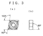
- FIG. 3(a) is a view of a throwing away insert seen from the axis direction of its through-hole with a circular cylindrical shape
- FIG. 3(b) is a view of a throwing away insert seen from a direction normal to its axis of the through-hole with a circular cylindrical shape.
Landscapes
- Chemical & Material Sciences (AREA)
- General Chemical & Material Sciences (AREA)
- Chemical Kinetics & Catalysis (AREA)
- Engineering & Computer Science (AREA)
- Materials Engineering (AREA)
- Mechanical Engineering (AREA)
- Metallurgy (AREA)
- Organic Chemistry (AREA)
- Inorganic Chemistry (AREA)
- Cutting Tools, Boring Holders, And Turrets (AREA)
- Chemical Vapour Deposition (AREA)
Applications Claiming Priority (4)
| Application Number | Priority Date | Filing Date | Title |
|---|---|---|---|
| JP79042/97 | 1997-03-13 | ||
| JP7904297 | 1997-03-13 | ||
| JP157642/97 | 1997-05-30 | ||
| JP9157642A JPH10310494A (ja) | 1996-05-31 | 1997-05-30 | ダイヤモンド被覆膜付き超硬部材の製造方法 |
Publications (1)
| Publication Number | Publication Date |
|---|---|
| EP0864668A1 true EP0864668A1 (fr) | 1998-09-16 |
Family
ID=26420118
Family Applications (1)
| Application Number | Title | Priority Date | Filing Date |
|---|---|---|---|
| EP97120754A Withdrawn EP0864668A1 (fr) | 1997-03-13 | 1997-11-26 | Elément ultra-dure revêtu de diamant et méthode pour sa fabrication |
Country Status (1)
| Country | Link |
|---|---|
| EP (1) | EP0864668A1 (fr) |
Cited By (3)
| Publication number | Priority date | Publication date | Assignee | Title |
|---|---|---|---|---|
| US6387502B1 (en) | 1998-09-04 | 2002-05-14 | Ngk Spark Plug Co., Ltd. | Diamond-coated hard metal member |
| US6705806B2 (en) | 1998-12-28 | 2004-03-16 | Ngk Spark Plug Co., Ltd. | Cutting tool coated with diamond |
| CN117626172A (zh) * | 2024-01-26 | 2024-03-01 | 南通硅胜新材料科技有限公司 | 一种真空镀膜的基体前处理工艺 |
Citations (3)
| Publication number | Priority date | Publication date | Assignee | Title |
|---|---|---|---|---|
| JPH02217398A (ja) * | 1989-02-17 | 1990-08-30 | Idemitsu Petrochem Co Ltd | ダイヤモンド類薄膜による被覆方法 |
| EP0445305A1 (fr) * | 1989-09-22 | 1991-09-11 | Showa Denko Kabushiki Kaisha | Procede de synthese de diamant depose en phase vapeur sur un substrat traite par voie electrochimique |
| JPH0920590A (ja) * | 1995-07-05 | 1997-01-21 | Ngk Spark Plug Co Ltd | ダイヤモンド膜付き超硬基材の製造方法 |
-
1997
- 1997-11-26 EP EP97120754A patent/EP0864668A1/fr not_active Withdrawn
Patent Citations (3)
| Publication number | Priority date | Publication date | Assignee | Title |
|---|---|---|---|---|
| JPH02217398A (ja) * | 1989-02-17 | 1990-08-30 | Idemitsu Petrochem Co Ltd | ダイヤモンド類薄膜による被覆方法 |
| EP0445305A1 (fr) * | 1989-09-22 | 1991-09-11 | Showa Denko Kabushiki Kaisha | Procede de synthese de diamant depose en phase vapeur sur un substrat traite par voie electrochimique |
| JPH0920590A (ja) * | 1995-07-05 | 1997-01-21 | Ngk Spark Plug Co Ltd | ダイヤモンド膜付き超硬基材の製造方法 |
Non-Patent Citations (2)
| Title |
|---|
| DATABASE WPI Section Ch Week 9041, Derwent World Patents Index; Class E36, AN 90-308593, XP002069043 * |
| DATABASE WPI Section Ch Week 9713, Derwent World Patents Index; Class L03, AN 97-140763, XP002069044 * |
Cited By (5)
| Publication number | Priority date | Publication date | Assignee | Title |
|---|---|---|---|---|
| US6387502B1 (en) | 1998-09-04 | 2002-05-14 | Ngk Spark Plug Co., Ltd. | Diamond-coated hard metal member |
| US6705806B2 (en) | 1998-12-28 | 2004-03-16 | Ngk Spark Plug Co., Ltd. | Cutting tool coated with diamond |
| US7179022B2 (en) | 1998-12-28 | 2007-02-20 | Ngk Spark Plug Co., Ltd. | Cutting tool coated with diamond |
| CN117626172A (zh) * | 2024-01-26 | 2024-03-01 | 南通硅胜新材料科技有限公司 | 一种真空镀膜的基体前处理工艺 |
| CN117626172B (zh) * | 2024-01-26 | 2024-04-12 | 南通硅胜新材料科技有限公司 | 一种真空镀膜的基体前处理工艺 |
Similar Documents
| Publication | Publication Date | Title |
|---|---|---|
| US6110240A (en) | Superhard article with diamond coat and method of manufacturing same | |
| EP0298729B1 (fr) | Outil de coupe | |
| EP2287359B1 (fr) | Plaquette de coupe enrobée | |
| EP2935647B1 (fr) | Outil de coupe revêtu et procédé pour sa fabrication | |
| KR20000034774A (ko) | 다이아몬드 코팅된 절삭공구와 그 제조방법 | |
| EP2576854B1 (fr) | Outil de coupe revêtu | |
| KR19990036281A (ko) | Cvd 다이아몬드 필름을 수용하기 위한 초경 합금 기판의 처리 방법 | |
| US6723389B2 (en) | Process for producing coated cemented carbide excellent in peel strength | |
| EP1016479A2 (fr) | Outil de coupe | |
| EP2074241A1 (fr) | Outil de découpe revêtu | |
| EP1253124B1 (fr) | Carbure cimenté fortement adhésif à surface revêtue et procédé de sa préparation | |
| JPS6315347B2 (fr) | ||
| EP0864668A1 (fr) | Elément ultra-dure revêtu de diamant et méthode pour sa fabrication | |
| Vogel et al. | Problems encountered with the introduction of ion plating to large‐scale coating of tools | |
| US5038645A (en) | Wear resistant cutting tools and shaping method | |
| EP1175949B1 (fr) | Carbure cementé revêtu | |
| JP3519260B2 (ja) | 耐剥離性に優れたダイヤモンド膜被覆硬質部材 | |
| JP2000212743A (ja) | 耐剥離性に優れた表面被覆焼結合金およびその製法 | |
| JPH0920590A (ja) | ダイヤモンド膜付き超硬基材の製造方法 | |
| JP3643639B2 (ja) | 超硬合金構造体、その製造方法及びそれを用いた切削工具 | |
| JP2000297342A (ja) | 表面調質超硬合金、被覆表面調質超硬合金およびその製法 | |
| JPH07223101A (ja) | 表面被覆超硬合金製切削工具 | |
| JPH10130092A (ja) | ダイヤモンド被覆焼結合金 | |
| JPH10226597A (ja) | ダイヤモンド被覆硬質部材 | |
| JPH11347805A (ja) | ダイヤモンド被覆工具部材およびその製造方法 |
Legal Events
| Date | Code | Title | Description |
|---|---|---|---|
| PUAI | Public reference made under article 153(3) epc to a published international application that has entered the european phase |
Free format text: ORIGINAL CODE: 0009012 |
|
| AK | Designated contracting states |
Kind code of ref document: A1 Designated state(s): DE FR GB |
|
| AX | Request for extension of the european patent |
Free format text: AL;LT;LV;MK;RO;SI |
|
| 17P | Request for examination filed |
Effective date: 19980820 |
|
| AKX | Designation fees paid |
Free format text: DE FR GB |
|
| RBV | Designated contracting states (corrected) |
Designated state(s): DE FR GB |
|
| 17Q | First examination report despatched |
Effective date: 20000922 |
|
| GRAH | Despatch of communication of intention to grant a patent |
Free format text: ORIGINAL CODE: EPIDOS IGRA |
|
| RTI1 | Title (correction) |
Free format text: METHOD FOR MANUFACTURING A SUPERHARD ARTICLE WITH A DIAMOND COATING |
|
| RTI1 | Title (correction) |
Free format text: METHOD FOR MANUFACTURING A SUPERHARD ARTICLE WITH A DIAMOND COATING |
|
| STAA | Information on the status of an ep patent application or granted ep patent |
Free format text: STATUS: THE APPLICATION IS DEEMED TO BE WITHDRAWN |
|
| 18D | Application deemed to be withdrawn |
Effective date: 20030301 |