EP0864728A2 - Kühlluftzufuhrsystem für die Schaufeln einer Gasturbine - Google Patents
Kühlluftzufuhrsystem für die Schaufeln einer Gasturbine Download PDFInfo
- Publication number
- EP0864728A2 EP0864728A2 EP98301537A EP98301537A EP0864728A2 EP 0864728 A2 EP0864728 A2 EP 0864728A2 EP 98301537 A EP98301537 A EP 98301537A EP 98301537 A EP98301537 A EP 98301537A EP 0864728 A2 EP0864728 A2 EP 0864728A2
- Authority
- EP
- European Patent Office
- Prior art keywords
- cooling air
- blade
- air
- passage
- rotating
- Prior art date
- Legal status (The legal status is an assumption and is not a legal conclusion. Google has not performed a legal analysis and makes no representation as to the accuracy of the status listed.)
- Granted
Links
- 238000001816 cooling Methods 0.000 title claims abstract description 182
- 238000007789 sealing Methods 0.000 claims description 6
- 239000007789 gas Substances 0.000 description 30
- 239000000567 combustion gas Substances 0.000 description 24
- 230000009545 invasion Effects 0.000 description 4
- 230000000694 effects Effects 0.000 description 3
- 238000010276 construction Methods 0.000 description 2
Images


Classifications
-
- F—MECHANICAL ENGINEERING; LIGHTING; HEATING; WEAPONS; BLASTING
- F01—MACHINES OR ENGINES IN GENERAL; ENGINE PLANTS IN GENERAL; STEAM ENGINES
- F01D—NON-POSITIVE DISPLACEMENT MACHINES OR ENGINES, e.g. STEAM TURBINES
- F01D5/00—Blades; Blade-carrying members; Heating, heat-insulating, cooling or antivibration means on the blades or the members
- F01D5/02—Blade-carrying members, e.g. rotors
- F01D5/08—Heating, heat-insulating or cooling means
-
- F—MECHANICAL ENGINEERING; LIGHTING; HEATING; WEAPONS; BLASTING
- F01—MACHINES OR ENGINES IN GENERAL; ENGINE PLANTS IN GENERAL; STEAM ENGINES
- F01D—NON-POSITIVE DISPLACEMENT MACHINES OR ENGINES, e.g. STEAM TURBINES
- F01D5/00—Blades; Blade-carrying members; Heating, heat-insulating, cooling or antivibration means on the blades or the members
- F01D5/12—Blades
- F01D5/14—Form or construction
- F01D5/18—Hollow blades, i.e. blades with cooling or heating channels or cavities; Heating, heat-insulating or cooling means on blades
- F01D5/187—Convection cooling
-
- F—MECHANICAL ENGINEERING; LIGHTING; HEATING; WEAPONS; BLASTING
- F01—MACHINES OR ENGINES IN GENERAL; ENGINE PLANTS IN GENERAL; STEAM ENGINES
- F01D—NON-POSITIVE DISPLACEMENT MACHINES OR ENGINES, e.g. STEAM TURBINES
- F01D9/00—Stators
- F01D9/06—Fluid supply conduits to nozzles or the like
- F01D9/065—Fluid supply or removal conduits traversing the working fluid flow, e.g. for lubrication-, cooling-, or sealing fluids
-
- F—MECHANICAL ENGINEERING; LIGHTING; HEATING; WEAPONS; BLASTING
- F05—INDEXING SCHEMES RELATING TO ENGINES OR PUMPS IN VARIOUS SUBCLASSES OF CLASSES F01-F04
- F05D—INDEXING SCHEME FOR ASPECTS RELATING TO NON-POSITIVE-DISPLACEMENT MACHINES OR ENGINES, GAS-TURBINES OR JET-PROPULSION PLANTS
- F05D2260/00—Function
- F05D2260/20—Heat transfer, e.g. cooling
- F05D2260/221—Improvement of heat transfer
- F05D2260/2212—Improvement of heat transfer by creating turbulence
Definitions
- the present invention relates to a blade cooling air supplying system for effectively cooling a blade of a gas turbine by the air, and particularly to a system which makes it a possible to cool rotating blade (moving blade) by the air when a rotor is cooled by vapor.
- Fig. 4 is a cross-sectional view of the interior of a conventional general gas turbine showing a flow of cooling air to a rotating blade.
- reference numerals 50, 51 and 52 respectively designate a stationary blade, an outer shroud and an inner shroud.
- Reference numeral 60 designates a rotating blade constructed such that this rotating blade 60 is attached to a rotor disk blade root portion 62 of a turbine disk 61 and is rotated between stationary blades 50.
- the rotating blade 60 is cooled by the air and is adapted to be cooled by using one portion of the rotor cooling air.
- a radial hole 65 is formed in the rotor disk blade root portion 62 and the rotor cooling air 100 is guided to each disk cavity 64.
- the rotor cooling air 100 is guided through the radial hole 65 to a lower portion of a platform 63, and is supplied to the rotating blade 60.
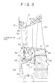
- Fig. 3 is a detailed view of the stationary and rotating blades in the gas turbine of the above construction.
- the stationary blade 50 has the outer shroud 51 and the inner shroud 52.
- An air pipe 53 axially extends through the interior of the stationary blade 50.
- air 110 for seal is guided from a side of the outer shroud 51 to a cavity 54 and flows out to a passage 56 through a hole 57.
- a pressure within the passage 56 is increased in comparison with that in a combustion gas passage and one portion of this pressure flows into the combustion gas passage so as to prevent the invasion of a high temperature gas.
- Reference numeral 55 designates a labyrinth seal similarly used to seal the high temperature gas.
- the cooling air supplied to the rotating blade 60 guides the rotor cooling air 100 into the disk cavity 64 and also guides the rotor cooling air 100 to a shank portion 61 surrounded by a seal plate 66 in a lower portion of the platform 63 through the radial hole 65 extending through the interior of the rotor disk blade root portion 62.
- the rotor cooling air 100 is then supplied from this shank portion 61 to a passage for cooling the rotating blade 60.
- the air from a compressor may be also cooled through a cooler instead of usage of one portion of the rotor cooling air and may be guided to the disk cavity 64.
- the blades of the conventional gas turbine are cooled by the air and the rotating blade 60 is particularly cooled by guiding one portion of the rotor cooling air.
- a cooling system using vapor instead of the air has been researched. When a rotor system is cooled by the vapor, no air for cooling can be obtained from the rotor so that no rotating blade can be cooled by the air in the conventional structure.
- the air 110 for seal is blown out to the cavity 54 of the stationary blade 50 from the air pipe 53 extending through the interior of the stationary blade.
- the interior of the cavity 54 is held at a high pressure and the pressure of the passage 56 is set to be higher than the pressure of the combustion gas passage so that the invasion of a high temperature gas into the interior of the stationary blade is prevented.
- the air 110 for seal blown out to the cavity 54 partially flows out to the high temperature combustion gas passage through the hole 57 and the passage 56. When an amount of this flowing-out air is increased, efficiency of the gas turbine is reduced.
- a first object of the present invention is to provide a blade cooling air supplying system of a gas turbine in which the air for cooling a rotating blade is supplied from a stationary blade to the rotating blade instead of using one portion of the air for cooling a rotor, and the rotating blade can be also cooled by the air when a vapor cooling system is adopted to cool the rotor.
- a second object of the present invention is to provide a blade cooling air supplying system of a gas turbine having a structure for effectively supplying the air for sealing the stationary blade in addition to the above first object.
- a third object of the present invention is the same as the first object with respect to the supply of the cooling air from the stationary blade to the rotating blade, but is to provide a blade cooling air supplying system of the gas turbine in which this cooling air from an air supplying system is utilized as the air for seal and can cool the rotating blade.
- the present invention provides the following (1), (2) and (3) means to respectively achieve the above-mentioned first, second and third objects.
- the cooling air is supplied from the air pipe of each stationary blade and is blown out to the inlet of the cooling air introducing portion on a rotating blade side from the cooling air passage arranged in the seal box.
- the cooling air is then guided from the cooling air introducing portion to the rotating blade.
- this cooling air can be directly supplied from the stationary blade to the rotating blade at a high pressure and a low temperature as they are. Accordingly, similar to the conventional air cooling for cooling the rotating blade by one portion of the rotor cooling air, the rotating blade can be effectively cooled by the air.
- Such a blade cooling air supplying system can be used as an air cooling system for the blades in a gas turbine in which the rotor is cooled by vapor.
- the entirety of the cooling air from the air pipe is used to cool the rotating blade.
- the air for sealing the stationary blade is separately transmitted through a leading edge portion of the stationary blade and cools this leading edge portion. Thereafter, this air is used to pressurize the cavity. Accordingly, in addition to the effects of the above (1) of the present invention, the cooling air is effectively utilized.
- the cooling air supplied from the air passage of the stationary blade first flows into the cavity and sets an internal pressure of the cavity to be higher than that of the combustion gas passage. Thereafter, the cooling air is guided to the rotating blade side cooling air passage and is supplied to the rotating blade. Accordingly, the cooling air is effectively utilized. As a result, an air amount escaping from a portion between the rotating and stationary blades to the combustion gas passage can be reduced.
- the cooling air supplying system for the blades can air cool the blades in a gas turbine in which the rotor is cooled by vapor.
- the gas turbine has plural rotating blades each attached to a rotor through a blade root portion and also has plural stationary blades arranged alternately with the rotating blades such that each of the stationary blades has outer and inner shrouds, a cavity for seal in a lower portion of the inner shroud, and a seal box in a lower portion of the cavity for seal
- the blade cooling air supplying system comprises an air pipe extending through each of said stationary blades from the outer shroud to the inner shroud and inserted into said seal box, a rotating blade side cooling air introducing portion arranged in the blade root portion of each of said rotating blades and guiding cooling air to each of said rotating blades, and a cooling air passage arranged in said seal box and communicated with said air pipe and opened toward an inlet of said rotating blade side cooling air introducing portion.
- the cooling air is blown out to the inlet of the cooling air introducing portion on the rotating blade side from the cooling air passage and is then sent from the cooling air introducing portion on the rotating blade side to each rotating blade.
- This cooling air can be directly supplied from each stationary blade to the rotating blade at a high pressure and a low temperature as they are. Accordingly, cooling effects of the rotating blade can be improved.
- the invention of this (1) can be used as an air cooling system for the blades in a gas turbine in which the rotor is cooled by vapor.
- the entirety of the cooling air supplied to said air pipe out of the cooling air supplied from an outer shroud side of each stationary blade is supplied to each of said rotating blades, and the cooling air supplied to a leading edge portion passage among the air for cooling each of said stationary blades is sent as the air for seal to the cavity of each of said stationary blades. Accordingly, the entirety of the cooling air from the air pipe is used to cool each rotating blade. The air for sealing each stationary blade is separately transmitted through a leading edge portion of the stationary blade and cools this leading edge portion. Thereafter, this air is used to pressurize the cavity. Accordingly, in addition to the effects of the above (1) of the present invention, the cooling air is effectively utilized.
- the above (3) of the present invention is a blade cooling air supplying system of a gas turbine having rotating and stationary blades similar to those of the above (1) and constructed such that the blade cooling air supplying system comprises an air passage extending through each of said stationary blades from the outside shroud to the inner shroud and communicated with said cavity, a rotating blade side cooling air passage arranged in the blade root portion of each of said rotating blades and guiding cooling air to each of said rotating blades, and a seal box side cooling air passage arranged in said seal box and connecting said cavity to said rotating blade side cooling air passage.
- the cooling air first flows into the cavity and sets an internal pressure of the cavity to be higher than that of the combustion gas passage. Thereafter, the cooling air is guided to the rotating blade side cooling air passage and is supplied to each rotating blade. Accordingly, the cooling air is efficiently utilized. As a result, the amount of air escaping from a portion between the rotating and stationary blades to the combustion gas passage can be reduced.
- the invention of the above (3) can be also used as a system for air cooling the blades in a gas turbine in which the rotor is cooled by vapor.
- Fig. 1 is a cross-sectional view of root portions of stationary and rotating blades to which a blade cooling air supplying system in accordance with a first embodiment of the present invention is applied.
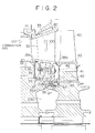
- Fig. 2 is a cross-sectional view of root portions of stationary and rotating blades to which a blade cooling air supplying system in accordance with a second embodiment of the present invention is applied.
- Fig. 3 is a cross-sectional view of a rotating blade in which a cooling air supplying system to the rotating blade of a conventional gas turbine is applied.
- Fig. 4 is a cross-sectional view of a blade portion of the conventional gas turbine showing a flow of cooling air to the rotating blade.
- Fig. 1 is a cross-sectional view of a blade portion to which a blade cooling air supplying system of a gas turbine in accordance with a first embodiment of the present invention is applied.
- reference numeral 10 designates a stationary blade having an outside shroud 11 and an inner shroud 12.
- Reference numeral 13 designates an air pipe extending through the interior of the stationary blade and the air 100 for cooling is guided by this air pipe 13.
- Reference numeral 14 designates a cavity arranged in a lower portion of the inner shroud 12.
- a tube 13a connected to the air pipe 13 hermetically passes through the interior of the cavity 14.
- Reference numeral 15 designates a seal box for supporting a labyrinth seal 15a.
- Reference numerals 16a and 16b designate passages formed by seal portions 12a, 12b of the inner shroud 12 in both end portions thereof.
- Reference numeral 17 designates an air hole extending through the seal box 15 and communicating the cavity 14 with the passage 16a.
- Reference numeral 18 designates a cooling air passage arranged in the seal box 15.
- the cooling air passage 18 communicates the tube 13a continuously connected to the air pipe 13 with a cooling air chamber 24 on a rotating blade side.
- An air passage 19A for seal guides the air 101 from the outer shroud 11.
- Air passages 19B, 19C, 19D, 19E and 19F form a serpentine cooling flow passage.
- Reference numerals 20, 21 and 22 respectively designate an unillustrated rotating blade, a shank portion and a rotor disk blade root portion.
- This rotor disk blade root portion 22 has a projecting portion 22a.
- a seal portion 28 is formed between this projecting portion 22a and the seal box 15 of the stationary blade 10.
- Reference numerals 23 and 24 respectively designate a platform and a cooling air chamber in the blade root portion 22.
- the cooling air chamber 24 is formed by the projecting portion 22a, the seal chamber 28, the seal box 15 of the stationary blade 10 and the labyrinth seal 15a.
- the cooling air chamber 24 is communicated with the cooling air passage 18 arranged in the seal box 15 on a stationary blade side.
- Reference numeral 25 designates a radial hole formed in the rotor disk blade root portion 22.
- the radial hole 25 is communicated with the cooling air chamber 24 and an air reservoir 27 formed in the blade root portion 22 and the shank portion 21.
- an air introducing portion is constructed by the cooling air passage 24, the radial hole 25 and the air reservoir 27.
- Reference numeral 26 designates a seal plate in a lower portion of the platform 23.
- the passage 16b is formed by the seal plate 26 and the seal portion 12b on a stationary blade side.
- a turbulator 70 is arranged within the air passages 19A to 19F of the stationary blade 10 to provide turbulence to a cooling air flow and improve a heat transfer rate.
- the rotor is cooled by vapor and a vapor cavity 200 is arranged.
- the rotor is cooled by the vapor from the vapor cavity 200.
- the stationary blade 10 and the rotating blade 20 are cooled by the air.
- One portion of the air 101 first flows into the interior of the stationary blade from the outside shroud 11 through the passage 19A on a leading edge side. This air cools the leading edge and is blown out to the cavity 14 and passes through the air hole 17 of the seal box 15 and also passes through the passage 16a at a pressure equal to or higher than a predetermined pressure.
- the air then passes through the seal portion 12a and partially flows out onto the side of a high temperature gas passage. Accordingly, a rotor side of the combustion gas passage is held at a pressure higher than the pressure of the combustion gas passage by this air 101 for seal so that the invasion of a high temperature gas onto the rotor side of the combustion gas passage is prevented.
- the remaining portion of the air 101 enters the passage 19B and is moved upward in the passage 19C from a lower portion of the passage 19B.
- Serpentine cooling is performed while the remaining portion of the air 101 sequentially passes through the passages 19D, 19E and 19F and is partially discharged from a trailing edge side. After this cooling, the air at a high temperature passes through the passage 16b and flows out to a gas flow passage on the trailing edge side from the seal portion 12b.
- the cooling air 100 flows into the air pipe 13 from the outside shroud 11 and passes through the tube 13a continuously connected to a lower portion of the air pipe 13.
- the cooling air 100 further enters the cooling air chamber 24 through the cooling air passage 18 and stays as cooling air at a high pressure and a low temperature.
- the cooling air entering the cooling air chamber 24 further enters the air reservoir 27 through the radial hole 25 on the rotating blade side, and is guided from the platform 23 to an air passage for cooling arranged in an unillustrated rotating blade 20, and cools the rotating blade 20.
- the air for cooling the rotating blade is supplied from only the air pipe 13 arranged in the stationary blade 10 and the tube 13a.
- the air pipe 13 and the tube 13a constitute an independent route. Accordingly, the air for cooling the rotating blade is directly supplied to the rotating blade 20 while the high pressure and the low temperature of the air are maintained. Therefore, the rotating blade 20 can be effectively cooled.
- the air 101 for seal within the cavity 14 is independently supplied from the passage 19A at a leading edge.
- the air 101 passing through this passage 19A cools a leading edge portion and is then used as a seal. Accordingly, the air 101 can be used for both seal and cooling so that the air can be effectively utilized.
- the air can be also supplied to the blades, especially the rotating blade 20 in the case of a gas turbine for cooling the rotor by vapor. Accordingly, the blades can be cooled by the air.
- Fig. 2 is a cross-sectional view of a blade portion to which a blade cooling air supplying system in accordance with a second embodiment of the present invention is applied.
- this second embodiment is characterized in that one portion of the air supplied from a stationary blade to cool a rotating blade can be also utilized as the air for sealing the stationary blade, and the air escaping from a portion between the rotating and stationary blades to a combustion gas passage is reduced by effectively utilizing the air.
- a stationary blade 30 has an outer shroud 31 and an inner shroud 32.
- Reference numeral 33 designates an air passage within the stationary blade. This air passage 33 may be formed within the stationary blade and may be also formed by arranging a tube.
- Reference numerals 34 and 35 respectively designate a cavity and a seal box. The seal box 35 supports a labyrinth seal 35a for sealing a portion between the seal box 35 and a rotating blade 40.
- Reference numerals 36 and 37 respectively designate a passage and an air passage.
- the air passage 37 is formed in the seal box 35 and communicates the cavity 34 with the passage 36.
- Reference numerals 38a and 38b designate seals between an end portion of the inside shroud 32 of the stationary blade 30 and an end portion of a platform 43 of the rotating blade 40 described later.
- Reference numeral 39 designates an air reservoir formed between the labyrinth seal 35a and a baffle plate 47.
- the baffle plate 47 is arranged between the labyrinth seal 35a and a rotor disk blade root portion 42 of the rotating blade 40.
- Reference numerals 40, 41 and 42 respectively designate a rotating blade and a shank portion formed in a lower portion of the platform 43, and a rotor disk blade root portion.
- Reference numerals 44 and 45 respectively designate cooling air passages.
- the cooling air passage 44 is formed such that this cooling air passage 44 extends through a rotor disk.
- the cooling air passage 44 is communicated with the air reservoir 39 and the cooling air passage 45 of the rotor disk blade root portion 42. Air passage portions of the rotor disk blade root portion 42 and the shank portion 41 are sealed by a seal plate 46 and the supplied cooling air does not escape to a combustion gas passage, but is reliably supplied to the rotating blade 40.
- reference numerals S and SF respectively designate a seal and a seal fin.
- the cooling air 100 from a compartment side flows into the cavity 34 from the interior of the stationary blade through the air passage 33.
- the cooling air 100 then passes through the air passage 37 and enters the air reservoir 39 through the labyrinth seal 35a at a pressure equal to or higher than a predetermined pressure.
- One portion of the air flowing out through the air passage 37 passes through the passage 36.
- this air has a pressure equal to or higher than that of a combustion gas at a high pressure
- the air passes through a seal 38a and flows out to the combustion gas passage.
- the interior of the cavity 34 is held at a pressure higher than that of the combustion gas passage so that the invasion of a high pressure combustion gas onto a rotor side of the combustion gas passage is prevented.
- the cooling air of the air reservoir 39 passes through the cooling air passages 44 and 45 and enters the shank portion 41 via an unillustrated passage formed in the rotor disk blade root portion 42.
- the cooling air is then supplied to a passage for cooling the rotating blade 40 and cools the rotating blade 40. After this cooling, the air is discharged to the combustion gas passage.
- Both sides of the shank portion 41 and the blade root portion 42 formed in a lower portion of the platform 43 are sealed by the seal plate 46 so that the cooling air can be reliably supplied to the rotating blade 40 without escaping this cooling air to the combustion gas passage.
- the cooling air 100 supplied from the air passage 33 of the stationary blade 30 is reliably supplied to the rotating blade 40 without escaping this cooling air to the combustion gas passage, and can cool the rotating blade 40. Further, one portion of the cooling air of the air passage 33 is supplied to the cavity 34 as the air for seal. Accordingly, the air for seal is sent to the cavity 34 by forming a dedicated passage for seal, and an air amount escaping to the combustion gas passage can be reduced in comparison with a system for almost escaping the air to the combustion gas passage.
- the cooling air can be also supplied to the rotating blade 40 in such a blade cooling air supplying system in the second embodiment even in the case of a gas turbine for cooling the rotor by vapor. Accordingly, the rotating blade can be cooled by the air.
Landscapes
- Engineering & Computer Science (AREA)
- Mechanical Engineering (AREA)
- General Engineering & Computer Science (AREA)
- Physics & Mathematics (AREA)
- Fluid Mechanics (AREA)
- Turbine Rotor Nozzle Sealing (AREA)
Applications Claiming Priority (3)
| Application Number | Priority Date | Filing Date | Title |
|---|---|---|---|
| JP05626897A JP3416447B2 (ja) | 1997-03-11 | 1997-03-11 | ガスタービンの翼冷却空気供給システム |
| JP56268/97 | 1997-03-11 | ||
| JP5626897 | 1997-03-11 |
Publications (3)
| Publication Number | Publication Date |
|---|---|
| EP0864728A2 true EP0864728A2 (de) | 1998-09-16 |
| EP0864728A3 EP0864728A3 (de) | 2000-05-10 |
| EP0864728B1 EP0864728B1 (de) | 2005-08-10 |
Family
ID=13022349
Family Applications (1)
| Application Number | Title | Priority Date | Filing Date |
|---|---|---|---|
| EP98301537A Expired - Lifetime EP0864728B1 (de) | 1997-03-11 | 1998-03-03 | Kühlluftzufuhrsystem für die Schaufeln einer Gasturbine |
Country Status (5)
| Country | Link |
|---|---|
| US (1) | US6077034A (de) |
| EP (1) | EP0864728B1 (de) |
| JP (1) | JP3416447B2 (de) |
| CA (1) | CA2231668C (de) |
| DE (1) | DE69831109T2 (de) |
Cited By (16)
| Publication number | Priority date | Publication date | Assignee | Title |
|---|---|---|---|---|
| EP1094200A1 (de) * | 1998-07-17 | 2001-04-25 | Mitsubishi Heavy Industries, Ltd. | Gekühlte Gasturbinenrotorschaufel |
| DE19960895A1 (de) * | 1999-12-17 | 2001-06-28 | Rolls Royce Deutschland | Mehrstufige Axialturbine einer Turbomaschine |
| EP1045114A3 (de) * | 1999-04-15 | 2002-10-30 | General Electric Company | Versorgungsrohransatz für die Kühlung der dritten Stufe einer Gasturbinenlaufschaufel |
| EP1057974A3 (de) * | 1999-05-31 | 2004-01-21 | Nuovo Pignone Holding S.P.A. | Gasturbinenleitapparat |
| GB2394257A (en) * | 2002-09-27 | 2004-04-21 | United Technologies Corp | Means for cooling a gas turbine engine sealing arrangement |
| EP1526251A1 (de) * | 2003-10-22 | 2005-04-27 | General Electric Company | Kühlkonfiguration für eine Turbinenschaufel |
| GB2467350A (en) * | 2009-02-02 | 2010-08-04 | Rolls Royce Plc | Cooling and sealing in gas turbine engine turbine stage |
| US7775764B2 (en) | 2006-02-15 | 2010-08-17 | Rolls-Royce Plc | Gas turbine engine rotor ventilation arrangement |
| EP3056680A1 (de) * | 2015-01-20 | 2016-08-17 | United Technologies Corporation | Leckageluftsysteme für turbomaschinen |
| GB2536628A (en) * | 2015-03-19 | 2016-09-28 | Rolls Royce Plc | HPT Integrated interstage seal and cooling air passageways |
| US20170114648A1 (en) * | 2015-10-27 | 2017-04-27 | General Electric Company | Turbine bucket having cooling passageway |
| US9885243B2 (en) | 2015-10-27 | 2018-02-06 | General Electric Company | Turbine bucket having outlet path in shroud |
| US10508554B2 (en) | 2015-10-27 | 2019-12-17 | General Electric Company | Turbine bucket having outlet path in shroud |
| EP3663522A1 (de) * | 2018-12-07 | 2020-06-10 | ANSALDO ENERGIA S.p.A. | Statoranordnung für eine gasturbine und gasturbine mit dieser statoranordnung |
| WO2022150036A1 (en) * | 2021-01-06 | 2022-07-14 | Siemens Energy Global GmbH & Co. KG | Turbine vane in gas turbine engine |
| RU2795241C2 (ru) * | 2018-12-07 | 2023-05-02 | Ансальдо Энергия С.П.А. | Статорный узел для газовой турбины и газовая турбина, содержащая такой статорный узел |
Families Citing this family (48)
| Publication number | Priority date | Publication date | Assignee | Title |
|---|---|---|---|---|
| CA2263508C (en) * | 1997-06-19 | 2003-08-19 | Mitsubishi Heavy Industries, Ltd. | Sealing device for gas turbine stator blades |
| US6146091A (en) * | 1998-03-03 | 2000-11-14 | Mitsubishi Heavy Industries, Ltd. | Gas turbine cooling structure |
| US6832891B2 (en) * | 2001-10-29 | 2004-12-21 | Man Turbomaschinen Ag | Device for sealing turbomachines |
| WO2003052240A2 (de) * | 2001-12-14 | 2003-06-26 | Alstom Technology Ltd | Gasturbinenanordnung |
| US6769865B2 (en) * | 2002-03-22 | 2004-08-03 | General Electric Company | Band cooled turbine nozzle |
| US6659716B1 (en) | 2002-07-15 | 2003-12-09 | Mitsubishi Heavy Industries, Ltd. | Gas turbine having thermally insulating rings |
| US20040017050A1 (en) * | 2002-07-29 | 2004-01-29 | Burdgick Steven Sebastian | Endface gap sealing for steam turbine diaphragm interstage packing seals and methods of retrofitting |
| US7137780B2 (en) * | 2004-06-17 | 2006-11-21 | Siemens Power Generation, Inc. | Internal cooling system for a turbine blade |
| US20080061515A1 (en) * | 2006-09-08 | 2008-03-13 | Eric Durocher | Rim seal for a gas turbine engine |
| US7785072B1 (en) | 2007-09-07 | 2010-08-31 | Florida Turbine Technologies, Inc. | Large chord turbine vane with serpentine flow cooling circuit |
| JP5502340B2 (ja) * | 2009-02-25 | 2014-05-28 | 三菱重工業株式会社 | タービンの冷却構造およびガスタービン |
| US8142141B2 (en) * | 2009-03-23 | 2012-03-27 | General Electric Company | Apparatus for turbine engine cooling air management |
| US8277172B2 (en) * | 2009-03-23 | 2012-10-02 | General Electric Company | Apparatus for turbine engine cooling air management |
| GB0916432D0 (en) * | 2009-09-21 | 2009-10-28 | Rolls Royce Plc | Separator device |
| EP2383435A1 (de) * | 2010-04-29 | 2011-11-02 | Siemens Aktiengesellschaft | Hohle Innenführung einer Turbinenschaufel |
| US20120183389A1 (en) * | 2011-01-13 | 2012-07-19 | Mhetras Shantanu P | Seal system for cooling fluid flow through a rotor assembly in a gas turbine engine |
| US8702375B1 (en) * | 2011-05-19 | 2014-04-22 | Florida Turbine Technologies, Inc. | Turbine stator vane |
| US8628294B1 (en) * | 2011-05-19 | 2014-01-14 | Florida Turbine Technologies, Inc. | Turbine stator vane with purge air channel |
| GB201112880D0 (en) * | 2011-07-27 | 2011-09-07 | Rolls Royce Plc | Blade cooling and sealing system |
| US9017013B2 (en) * | 2012-02-07 | 2015-04-28 | Siemens Aktiengesellschaft | Gas turbine engine with improved cooling between turbine rotor disk elements |
| US9017014B2 (en) * | 2013-06-28 | 2015-04-28 | Siemens Energy, Inc. | Aft outer rim seal arrangement |
| US9638041B2 (en) | 2013-10-23 | 2017-05-02 | General Electric Company | Turbine bucket having non-axisymmetric base contour |
| US9551226B2 (en) | 2013-10-23 | 2017-01-24 | General Electric Company | Turbine bucket with endwall contour and airfoil profile |
| US9528379B2 (en) | 2013-10-23 | 2016-12-27 | General Electric Company | Turbine bucket having serpentine core |
| US9797258B2 (en) * | 2013-10-23 | 2017-10-24 | General Electric Company | Turbine bucket including cooling passage with turn |
| US9670784B2 (en) | 2013-10-23 | 2017-06-06 | General Electric Company | Turbine bucket base having serpentine cooling passage with leading edge cooling |
| WO2016025056A2 (en) | 2014-05-29 | 2016-02-18 | General Electric Company | Turbine engine and particle separators therefore |
| US11033845B2 (en) | 2014-05-29 | 2021-06-15 | General Electric Company | Turbine engine and particle separators therefore |
| DE112015003047B4 (de) | 2014-06-30 | 2021-08-26 | Mitsubishi Power, Ltd. | Turbinenleitschaufel, turbine und verfahren zum modifizieren einer turbinenleitschaufel |
| US9885254B2 (en) * | 2015-04-24 | 2018-02-06 | United Technologies Corporation | Mid turbine frame including a sealed torque box |
| US10107108B2 (en) | 2015-04-29 | 2018-10-23 | General Electric Company | Rotor blade having a flared tip |
| US9970299B2 (en) | 2015-09-16 | 2018-05-15 | General Electric Company | Mixing chambers for turbine wheel space cooling |
| US10060280B2 (en) * | 2015-10-15 | 2018-08-28 | United Technologies Corporation | Turbine cavity sealing assembly |
| US10125632B2 (en) | 2015-10-20 | 2018-11-13 | General Electric Company | Wheel space purge flow mixing chamber |
| US10132195B2 (en) | 2015-10-20 | 2018-11-20 | General Electric Company | Wheel space purge flow mixing chamber |
| US20170198602A1 (en) * | 2016-01-11 | 2017-07-13 | General Electric Company | Gas turbine engine with a cooled nozzle segment |
| US10519873B2 (en) * | 2016-04-06 | 2019-12-31 | General Electric Company | Air bypass system for rotor shaft cooling |
| US10633996B2 (en) | 2016-11-17 | 2020-04-28 | Rolls-Royce Corporation | Turbine cooling system |
| US10830058B2 (en) | 2016-11-30 | 2020-11-10 | Rolls-Royce Corporation | Turbine engine components with cooling features |
| EP3342991B1 (de) * | 2016-12-30 | 2020-10-14 | Ansaldo Energia IP UK Limited | Prallplatten für kühlung in einer gasturbine |
| US10633992B2 (en) | 2017-03-08 | 2020-04-28 | Pratt & Whitney Canada Corp. | Rim seal |
| JP6996947B2 (ja) | 2017-11-09 | 2022-01-17 | 三菱パワー株式会社 | タービン翼及びガスタービン |
| CN111963320B (zh) * | 2020-08-24 | 2021-08-24 | 浙江燃创透平机械股份有限公司 | 一种燃气轮机级间密封环结构 |
| FR3121470B1 (fr) * | 2021-03-31 | 2023-09-22 | Safran Aircraft Engines | Dispositif d’étanchéité et de réinjection d’un flux de contournement pour distributeur de turbine |
| US11591911B2 (en) | 2021-04-23 | 2023-02-28 | Raytheon Technologies Corporation | Pressure gain for cooling flow in aircraft engines |
| JP7847031B2 (ja) * | 2022-05-06 | 2026-04-16 | 三菱重工業株式会社 | タービン翼及びガスタービン |
| US12000308B2 (en) * | 2022-08-23 | 2024-06-04 | General Electric Company | Rotor blade assemblies for turbine engines |
| CN119840030B (zh) * | 2025-03-24 | 2025-06-13 | 常州圣雅塑母粒有限公司 | 一种母粒原料混料贮存装置 |
Family Cites Families (11)
| Publication number | Priority date | Publication date | Assignee | Title |
|---|---|---|---|---|
| US2919891A (en) * | 1957-06-17 | 1960-01-05 | Gen Electric | Gas turbine diaphragm assembly |
| GB938247A (en) | 1962-03-26 | 1963-10-02 | Rolls Royce | Gas turbine engine having cooled turbine blading |
| US3945758A (en) | 1974-02-28 | 1976-03-23 | Westinghouse Electric Corporation | Cooling system for a gas turbine |
| US4113406A (en) * | 1976-11-17 | 1978-09-12 | Westinghouse Electric Corp. | Cooling system for a gas turbine engine |
| JPS5979006A (ja) * | 1982-10-27 | 1984-05-08 | Hitachi Ltd | ガスタ−ビン空冷翼 |
| US4930980A (en) * | 1989-02-15 | 1990-06-05 | Westinghouse Electric Corp. | Cooled turbine vane |
| US5253976A (en) * | 1991-11-19 | 1993-10-19 | General Electric Company | Integrated steam and air cooling for combined cycle gas turbines |
| DE69305326T2 (de) * | 1992-02-10 | 1997-05-07 | United Technologies Corp | Ejektor für kühlfluid |
| US5217348A (en) * | 1992-09-24 | 1993-06-08 | United Technologies Corporation | Turbine vane assembly with integrally cast cooling fluid nozzle |
| US5488825A (en) * | 1994-10-31 | 1996-02-06 | Westinghouse Electric Corporation | Gas turbine vane with enhanced cooling |
| ES2144147T3 (es) * | 1994-11-10 | 2000-06-01 | Siemens Westinghouse Power | Alabe de turbina de gas con mortaja interna refrigerada. |
-
1997
- 1997-03-11 JP JP05626897A patent/JP3416447B2/ja not_active Expired - Fee Related
-
1998
- 1998-03-03 DE DE69831109T patent/DE69831109T2/de not_active Expired - Lifetime
- 1998-03-03 EP EP98301537A patent/EP0864728B1/de not_active Expired - Lifetime
- 1998-03-10 CA CA002231668A patent/CA2231668C/en not_active Expired - Fee Related
- 1998-03-11 US US09/038,451 patent/US6077034A/en not_active Expired - Lifetime
Non-Patent Citations (1)
| Title |
|---|
| None |
Cited By (23)
| Publication number | Priority date | Publication date | Assignee | Title |
|---|---|---|---|---|
| EP1094200A1 (de) * | 1998-07-17 | 2001-04-25 | Mitsubishi Heavy Industries, Ltd. | Gekühlte Gasturbinenrotorschaufel |
| EP1045114A3 (de) * | 1999-04-15 | 2002-10-30 | General Electric Company | Versorgungsrohransatz für die Kühlung der dritten Stufe einer Gasturbinenlaufschaufel |
| EP1057974A3 (de) * | 1999-05-31 | 2004-01-21 | Nuovo Pignone Holding S.P.A. | Gasturbinenleitapparat |
| DE19960895A1 (de) * | 1999-12-17 | 2001-06-28 | Rolls Royce Deutschland | Mehrstufige Axialturbine einer Turbomaschine |
| GB2394257A (en) * | 2002-09-27 | 2004-04-21 | United Technologies Corp | Means for cooling a gas turbine engine sealing arrangement |
| US6884023B2 (en) | 2002-09-27 | 2005-04-26 | United Technologies Corporation | Integral swirl knife edge injection assembly |
| GB2394257B (en) * | 2002-09-27 | 2005-06-08 | United Technologies Corp | Seal cooling system |
| EP1526251A1 (de) * | 2003-10-22 | 2005-04-27 | General Electric Company | Kühlkonfiguration für eine Turbinenschaufel |
| US6929445B2 (en) | 2003-10-22 | 2005-08-16 | General Electric Company | Split flow turbine nozzle |
| US7775764B2 (en) | 2006-02-15 | 2010-08-17 | Rolls-Royce Plc | Gas turbine engine rotor ventilation arrangement |
| GB2467350A (en) * | 2009-02-02 | 2010-08-04 | Rolls Royce Plc | Cooling and sealing in gas turbine engine turbine stage |
| US9938842B2 (en) | 2015-01-20 | 2018-04-10 | United Technologies Corporation | Leakage air systems for turbomachines |
| EP3056680A1 (de) * | 2015-01-20 | 2016-08-17 | United Technologies Corporation | Leckageluftsysteme für turbomaschinen |
| GB2536628A (en) * | 2015-03-19 | 2016-09-28 | Rolls Royce Plc | HPT Integrated interstage seal and cooling air passageways |
| US10156145B2 (en) * | 2015-10-27 | 2018-12-18 | General Electric Company | Turbine bucket having cooling passageway |
| US9885243B2 (en) | 2015-10-27 | 2018-02-06 | General Electric Company | Turbine bucket having outlet path in shroud |
| US20170114648A1 (en) * | 2015-10-27 | 2017-04-27 | General Electric Company | Turbine bucket having cooling passageway |
| US10508554B2 (en) | 2015-10-27 | 2019-12-17 | General Electric Company | Turbine bucket having outlet path in shroud |
| US11078797B2 (en) | 2015-10-27 | 2021-08-03 | General Electric Company | Turbine bucket having outlet path in shroud |
| EP3663522A1 (de) * | 2018-12-07 | 2020-06-10 | ANSALDO ENERGIA S.p.A. | Statoranordnung für eine gasturbine und gasturbine mit dieser statoranordnung |
| RU2795241C2 (ru) * | 2018-12-07 | 2023-05-02 | Ансальдо Энергия С.П.А. | Статорный узел для газовой турбины и газовая турбина, содержащая такой статорный узел |
| WO2022150036A1 (en) * | 2021-01-06 | 2022-07-14 | Siemens Energy Global GmbH & Co. KG | Turbine vane in gas turbine engine |
| US12116906B2 (en) | 2021-01-06 | 2024-10-15 | Siemens Energy Global GmbH & Co. KG | Turbine vane in gas turbine engine |
Also Published As
| Publication number | Publication date |
|---|---|
| US6077034A (en) | 2000-06-20 |
| DE69831109D1 (de) | 2005-09-15 |
| CA2231668A1 (en) | 1998-09-11 |
| JPH10252410A (ja) | 1998-09-22 |
| JP3416447B2 (ja) | 2003-06-16 |
| DE69831109T2 (de) | 2006-06-08 |
| EP0864728B1 (de) | 2005-08-10 |
| EP0864728A3 (de) | 2000-05-10 |
| CA2231668C (en) | 2001-08-21 |
Similar Documents
| Publication | Publication Date | Title |
|---|---|---|
| EP0864728A2 (de) | Kühlluftzufuhrsystem für die Schaufeln einer Gasturbine | |
| US6126389A (en) | Impingement cooling for the shroud of a gas turbine | |
| JP3978143B2 (ja) | 静翼の冷却構造及びガスタービン | |
| JP3631500B2 (ja) | ガスタービン用の一体化蒸気/空気冷却装置及びガスタービン用の冷却装置を動作する方法 | |
| US5480281A (en) | Impingement cooling apparatus for turbine shrouds having ducts of increasing cross-sectional area in the direction of post-impingement cooling flow | |
| JP4130540B2 (ja) | ガスタービンノズル壁を局部的に冷却するための装置及び方法 | |
| EP1116861B1 (de) | Kreislauf zum Kühlen von Gasturbinenschaufeln | |
| US6089822A (en) | Gas turbine stationary blade | |
| US5711650A (en) | Gas turbine airfoil cooling | |
| JP3426902B2 (ja) | ガスタービン冷却静翼 | |
| US4930980A (en) | Cooled turbine vane | |
| US6857848B2 (en) | Gap seal in a gas turbine | |
| US20100098554A1 (en) | Blade for a rotor | |
| CA2155375A1 (en) | Cooling circuit for turbine stator vane trailing edge | |
| JP2005163791A (ja) | タービンノズルセグメントの側壁を対流冷却するための方法及び装置 | |
| JPH08326556A (ja) | ガスタービンエンジンの空気流分配システム | |
| GB2298246A (en) | Turbine-blad-tip-sealing arrangement comprising a shroud band | |
| EP1124039A1 (de) | Vorrichtung zur Prallkühlung des Deckbandes in einer Gasturbine | |
| US7121797B2 (en) | Cooled turbine rotor wheel, in particular, a high-pressure turbine rotor wheel for an aircraft engine | |
| EP1098070A1 (de) | Dampfturbine mit verbesserter Gehäusekühlvorrichtung | |
| EP0911488A1 (de) | Kühlung von statorschaufeln in gasturbinen | |
| JPS6364601B2 (de) | ||
| JP2001221065A (ja) | ガスタービンシュラウドのインピンジメント冷却 | |
| JP2001107703A (ja) | ガスタービン | |
| CA2424166C (en) | Gas collection pipe carrying hot gas |
Legal Events
| Date | Code | Title | Description |
|---|---|---|---|
| PUAI | Public reference made under article 153(3) epc to a published international application that has entered the european phase |
Free format text: ORIGINAL CODE: 0009012 |
|
| 17P | Request for examination filed |
Effective date: 19980309 |
|
| AK | Designated contracting states |
Kind code of ref document: A2 Designated state(s): CH DE FR GB IT LI |
|
| AX | Request for extension of the european patent |
Free format text: AL;LT;LV;MK;RO;SI |
|
| PUAL | Search report despatched |
Free format text: ORIGINAL CODE: 0009013 |
|
| AK | Designated contracting states |
Kind code of ref document: A3 Designated state(s): AT BE CH DE DK ES FI FR GB GR IE IT LI LU MC NL PT SE |
|
| AX | Request for extension of the european patent |
Free format text: AL;LT;LV;MK;RO;SI |
|
| RIC1 | Information provided on ipc code assigned before grant |
Free format text: 7F 01D 5/08 A, 7F 01D 5/18 B, 7F 01D 9/06 B, 7F 01D 11/00 B |
|
| AKX | Designation fees paid |
Free format text: CH DE FR GB IT LI |
|
| 17Q | First examination report despatched |
Effective date: 20031021 |
|
| GRAP | Despatch of communication of intention to grant a patent |
Free format text: ORIGINAL CODE: EPIDOSNIGR1 |
|
| GRAS | Grant fee paid |
Free format text: ORIGINAL CODE: EPIDOSNIGR3 |
|
| GRAA | (expected) grant |
Free format text: ORIGINAL CODE: 0009210 |
|
| AK | Designated contracting states |
Kind code of ref document: B1 Designated state(s): CH DE FR GB IT LI |
|
| REG | Reference to a national code |
Ref country code: GB Ref legal event code: FG4D |
|
| REG | Reference to a national code |
Ref country code: CH Ref legal event code: EP |
|
| REF | Corresponds to: |
Ref document number: 69831109 Country of ref document: DE Date of ref document: 20050915 Kind code of ref document: P |
|
| REG | Reference to a national code |
Ref country code: CH Ref legal event code: NV Representative=s name: KIRKER & CIE SA |
|
| PLBE | No opposition filed within time limit |
Free format text: ORIGINAL CODE: 0009261 |
|
| STAA | Information on the status of an ep patent application or granted ep patent |
Free format text: STATUS: NO OPPOSITION FILED WITHIN TIME LIMIT |
|
| 26N | No opposition filed |
Effective date: 20060511 |
|
| PG25 | Lapsed in a contracting state [announced via postgrant information from national office to epo] |
Ref country code: FR Free format text: LAPSE BECAUSE OF FAILURE TO SUBMIT A TRANSLATION OF THE DESCRIPTION OR TO PAY THE FEE WITHIN THE PRESCRIBED TIME-LIMIT Effective date: 20060811 |
|
| EN | Fr: translation not filed | ||
| PG25 | Lapsed in a contracting state [announced via postgrant information from national office to epo] |
Ref country code: FR Free format text: LAPSE BECAUSE OF FAILURE TO SUBMIT A TRANSLATION OF THE DESCRIPTION OR TO PAY THE FEE WITHIN THE PRESCRIBED TIME-LIMIT Effective date: 20050810 |
|
| REG | Reference to a national code |
Ref country code: DE Ref legal event code: R082 Ref document number: 69831109 Country of ref document: DE Representative=s name: PATENTANWAELTE GEYER, FEHNERS & PARTNER MBB, DE Ref country code: DE Ref legal event code: R082 Ref document number: 69831109 Country of ref document: DE Representative=s name: GEYER, FEHNERS & PARTNER (G.B.R.), DE Ref country code: DE Ref legal event code: R081 Ref document number: 69831109 Country of ref document: DE Owner name: MITSUBISHI HITACHI POWER SYSTEMS, LTD., YOKOHA, JP Free format text: FORMER OWNER: MITSUBISHI HEAVY INDUSTRIES, LTD., TOKYO, JP |
|
| REG | Reference to a national code |
Ref country code: GB Ref legal event code: 732E Free format text: REGISTERED BETWEEN 20151203 AND 20151209 |
|
| PGFP | Annual fee paid to national office [announced via postgrant information from national office to epo] |
Ref country code: CH Payment date: 20170314 Year of fee payment: 20 Ref country code: DE Payment date: 20170228 Year of fee payment: 20 |
|
| PGFP | Annual fee paid to national office [announced via postgrant information from national office to epo] |
Ref country code: GB Payment date: 20170301 Year of fee payment: 20 |
|
| PGFP | Annual fee paid to national office [announced via postgrant information from national office to epo] |
Ref country code: IT Payment date: 20170320 Year of fee payment: 20 |
|
| REG | Reference to a national code |
Ref country code: CH Ref legal event code: PCOW Free format text: NEW ADDRESS: 16-5, KONAN 2-CHOME MINATO-KU, TOKYO 108-8215 (JP) |
|
| REG | Reference to a national code |
Ref country code: CH Ref legal event code: PUE Owner name: MITSUBISHI HITACHI POWER SYSTEMS, LTD., JP Free format text: FORMER OWNER: MITSUBISHI HEAVY INDUSTRIES, LTD., JP Ref country code: CH Ref legal event code: NV Representative=s name: SCHNEIDER FELDMANN AG PATENT- UND MARKENANWAEL, CH |
|
| REG | Reference to a national code |
Ref country code: DE Ref legal event code: R071 Ref document number: 69831109 Country of ref document: DE |
|
| REG | Reference to a national code |
Ref country code: CH Ref legal event code: PL |
|
| REG | Reference to a national code |
Ref country code: GB Ref legal event code: PE20 Expiry date: 20180302 |
|
| PG25 | Lapsed in a contracting state [announced via postgrant information from national office to epo] |
Ref country code: GB Free format text: LAPSE BECAUSE OF EXPIRATION OF PROTECTION Effective date: 20180302 |