EP0864737B1 - Dispositif de commande pour un moteur à combustion interne suralimenté - Google Patents
Dispositif de commande pour un moteur à combustion interne suralimenté Download PDFInfo
- Publication number
- EP0864737B1 EP0864737B1 EP98103089A EP98103089A EP0864737B1 EP 0864737 B1 EP0864737 B1 EP 0864737B1 EP 98103089 A EP98103089 A EP 98103089A EP 98103089 A EP98103089 A EP 98103089A EP 0864737 B1 EP0864737 B1 EP 0864737B1
- Authority
- EP
- European Patent Office
- Prior art keywords
- exhaust
- plug
- control device
- gas turbine
- exhaust gas
- Prior art date
- Legal status (The legal status is an assumption and is not a legal conclusion. Google has not performed a legal analysis and makes no representation as to the accuracy of the status listed.)
- Expired - Lifetime
Links
Images


Classifications
-
- F—MECHANICAL ENGINEERING; LIGHTING; HEATING; WEAPONS; BLASTING
- F02—COMBUSTION ENGINES; HOT-GAS OR COMBUSTION-PRODUCT ENGINE PLANTS
- F02B—INTERNAL-COMBUSTION PISTON ENGINES; COMBUSTION ENGINES IN GENERAL
- F02B37/00—Engines characterised by provision of pumps driven at least for part of the time by exhaust
- F02B37/12—Control of the pumps
- F02B37/18—Control of the pumps by bypassing exhaust from the inlet to the outlet of turbine or to the atmosphere
- F02B37/183—Arrangements of bypass valves or actuators therefor
-
- F—MECHANICAL ENGINEERING; LIGHTING; HEATING; WEAPONS; BLASTING
- F02—COMBUSTION ENGINES; HOT-GAS OR COMBUSTION-PRODUCT ENGINE PLANTS
- F02B—INTERNAL-COMBUSTION PISTON ENGINES; COMBUSTION ENGINES IN GENERAL
- F02B37/00—Engines characterised by provision of pumps driven at least for part of the time by exhaust
- F02B37/001—Engines characterised by provision of pumps driven at least for part of the time by exhaust using exhaust drives arranged in parallel
- F02B37/002—Engines characterised by provision of pumps driven at least for part of the time by exhaust using exhaust drives arranged in parallel the exhaust supply to one of the exhaust drives can be interrupted
-
- F—MECHANICAL ENGINEERING; LIGHTING; HEATING; WEAPONS; BLASTING
- F02—COMBUSTION ENGINES; HOT-GAS OR COMBUSTION-PRODUCT ENGINE PLANTS
- F02B—INTERNAL-COMBUSTION PISTON ENGINES; COMBUSTION ENGINES IN GENERAL
- F02B37/00—Engines characterised by provision of pumps driven at least for part of the time by exhaust
- F02B37/013—Engines characterised by provision of pumps driven at least for part of the time by exhaust with exhaust-driven pumps arranged in series
-
- F—MECHANICAL ENGINEERING; LIGHTING; HEATING; WEAPONS; BLASTING
- F02—COMBUSTION ENGINES; HOT-GAS OR COMBUSTION-PRODUCT ENGINE PLANTS
- F02D—CONTROLLING COMBUSTION ENGINES
- F02D9/00—Controlling engines by throttling air or fuel-and-air induction conduits or exhaust conduits
- F02D9/04—Controlling engines by throttling air or fuel-and-air induction conduits or exhaust conduits concerning exhaust conduits
- F02D9/06—Exhaust brakes
-
- Y—GENERAL TAGGING OF NEW TECHNOLOGICAL DEVELOPMENTS; GENERAL TAGGING OF CROSS-SECTIONAL TECHNOLOGIES SPANNING OVER SEVERAL SECTIONS OF THE IPC; TECHNICAL SUBJECTS COVERED BY FORMER USPC CROSS-REFERENCE ART COLLECTIONS [XRACs] AND DIGESTS
- Y02—TECHNOLOGIES OR APPLICATIONS FOR MITIGATION OR ADAPTATION AGAINST CLIMATE CHANGE
- Y02T—CLIMATE CHANGE MITIGATION TECHNOLOGIES RELATED TO TRANSPORTATION
- Y02T10/00—Road transport of goods or passengers
- Y02T10/10—Internal combustion engine [ICE] based vehicles
- Y02T10/12—Improving ICE efficiencies
Definitions
- the invention relates to a supercharged internal combustion engine according to the generic term.
- a supercharged internal combustion engine is known from DE 25 44 471 A1, in which two Exhaust gas turbochargers are connected in series.
- the exhaust gas coming from an exhaust manifold first passes through the first exhaust gas turbine of the first exhaust gas turbocharger. Then the exhaust gas flows through the second Exhaust gas turbine of the second exhaust gas turbocharger.
- the exhaust gas can be regulated by means of a control device on the first Exhaust gas turbine are passed via a bypass directly into the second exhaust gas turbine.
- the control device has three connections, a first one Connection establishes the connection with the exhaust manifold.
- a second connection connects the control device to the input of the first exhaust gas turbine and third connection connects control device and bypass line.
- the exit of the first Exhaust gas turbine is always via a channel with the entrance of the second exhaust gas turbine in connection.
- the invention lies Task to design the control device so that it together with the Exhaust gas turbochargers form a unit with the smallest possible construction volume and Function of a throttle valve for the engine brake integrated in the control device is.
- the control device is together with the two exhaust gas turbochargers to form an organic unit with a relatively small construction volume summarized. Due to the compact design, flow and Enthalpy losses minimized.
- By rotating the chick from the starting position will bypass the first exhaust gas turbine and only the second exhaust gas turbine for the flows through stationary operation.
- Another turn of the chick blocks the way of the exhaust manifold and thus acts as a throttle in engine braking, a separate one Throttle valve is omitted.
- the control device 5 also has a first and a second connection 6, 7, the first connection 6 having two channels with an inlet 8 of a first exhaust gas turbine 9 of the first exhaust gas turbocharger 10 is connected.
- the second port 7 is again double flow with an input 11 of a second exhaust gas turbine 12 of the second Exhaust gas turbocharger 13 connected.
- the output 14 of the first exhaust gas turbine 9 is direct connected to the inlet 11 of the second exhaust gas turbine 12 by means of a duct 15.
- the exhaust pipe 4 with the input 11 of the second exhaust gas turbine 12 are connected.
- the exhaust gas bypasses the first Exhaust gas turbine 9 and flows directly through the second exhaust gas turbine 12.
- the reversal can be carried out controllably so that the first exhaust gas turbine is still partially loaded and does not drop abruptly in speed before the second exhaust gas turbine 12 starts up.
- the inventive design of the control device 5 as a rotary valve is off Fig. 2 can be seen.
- the control device 5 consists of a housing 16 with molded double-flow exhaust pipe 4, which on the exhaust lines 2, 3 of the internal combustion engine 1 (Fig. 1) is connected.
- the housing 16 also has a first and second connection 6, 7, each of which is also double-flow.
- the first port 6 opens into the inlet 8 of the first exhaust gas turbine 9, the second Port 7 is connected to the input 11 of the second exhaust gas turbine 12.
- the output of the first exhaust gas turbine is clearly shown in FIG. 4 Channel 15 connected directly to the input 11 of the second exhaust gas turbine 12.
- a chick 17 is rotatably mounted, which has two paths 18, 19. This two paths 18, 19 allow the optional connection of exhaust pipe 4 with the first connection 6 or. the connection from the exhaust pipe 4 to the second connection 7.
- Another position of the plug 17 blocks the exhaust pipe when the engine brakes 4.
- the plug 17 is rotatably mounted in the housing 16 and has to compensate of thermal deformations a radial play to the housing 16.
- the sealing is carried out by radial sealing strips 18.
- the exhaust gas turbines 9, 12 form together with the control device 5 a compact structural unit of minimal construction volume, which immediately is flanged to internal combustion engine 1 via exhaust lines 2, 3.
- the Flow paths from the exhaust lines 2, 3 to the exhaust gas turbines 9, 12 are so short kept as possible so that flow losses and enthalpy losses through Cooling can be reduced to a minimum.
- Fig. 3 shows a longitudinal section III-III through the chick 17.
- the chick 17 contains the Paths 18 and 19 which are again double-flow.
- the gasket on the perimeter take over radial sealing strips 18a, of which only one in section III-III see is.
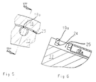
- the axial sealing takes place by means of piston rings 19a on the front Ends of the plug 17 are arranged lying in grooves. A detailed description the radial sealing strip 18a and the piston rings 19a can be seen in FIGS. 5, 6 forth.
- the rotation of the plug 17 takes place from the outside via the shaft 20, which in the Housing 16 (Fig. 2) is mounted.
- Fig. 4 shows a side view of the control device 5 with channel 15.
- a flange 21 is with the exit, not shown, of the first exhaust gas turbine 9 and the flange 22 connected to the input 11 of the second exhaust gas turbine 12 (FIG. 2).
- the wave 20, which is rotatably connected to the plug 17 of the rotary valve by one Air cylinders or the like are driven.
- Figures 5 and 6 represent forms of radial and axial sealing. 5 there is a radial gap 23 between the plug 17 and the housing 16 to absorb thermal deformations.
- the seal creates a radial Sealing strip 18a.
- This consists of a longitudinally slotted tube, which is pushed into an axial bore in the chick 17. Through the longitudinal slot, the Sealing strip a spring action, through which the sealing strip 18a against the inner wall the housing is pressed. The sealing strips 18a are even over the circumference distributed.
- Fig. 6 shows in section VI-VI the axial sealing by means of piston rings 19a, which are arranged in grooves 24 in the chick 17. As shown in Fig. 3, the piston rings 19a arranged at the front ends of the plug 17. A sealing strip 18a can be seen in section, it is inserted into the bore 25.
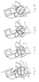
- FIGS. 7 to 10 all of which are in section Represent VII-VII of FIG. 4.
- the chick 17 connects the exhaust pipe 4 via the path 18 with the Input 8 of the first exhaust gas turbine 9 (Fig. 2).
- the output of the first exhaust turbine 9 is connected to nozzle 21 which opens into the channel 15, as shown in Fig. 4.
- the exhaust gas passes from the first exhaust gas turbine 9 the duct 15 to the inlet 11 of the second exhaust gas turbine 12. Both exhaust gas turbines 9, 12 are thus connected in series.
- the plug 17 If the plug 17 is rotated into a position as shown in FIG. 8, it already reaches part of the exhaust gas from the exhaust pipe 4 via the path 19 to the entrance 11 of the second exhaust gas turbine 12, while still part of the exhaust gas via path 18 through the first exhaust turbine 9 flows. 8 has the advantage that the first exhaust gas turbine 9 does not fall back abruptly as long as the exhaust gas turbine 12 is starting up is understood, otherwise a decrease in the performance of the internal combustion engine 1 occur, combined with an undesirable soot surge.
- the plug 17 When the engine brake is actuated, the plug 17 swivels into that shown in FIG. 10 Position and blocks the exhaust pipe. 5 between chicks 17 and housing 16 a radial gap 23 is provided, the dynamic pressure in the exhaust pipe 4 limited to a desired level during engine braking operation.
Landscapes
- Engineering & Computer Science (AREA)
- Chemical & Material Sciences (AREA)
- Combustion & Propulsion (AREA)
- Mechanical Engineering (AREA)
- General Engineering & Computer Science (AREA)
- Supercharger (AREA)
Claims (2)
- Dispositif de commande d'un moteur à combustion interne suralimenté comportant deux turbocompresseurs de gaz d'échappement branchés en série, et un dispositif de commande reliant un premier collecteur de gaz d'échappement du moteur à combustion interne, par un premier branchement à l'entrée d'une première turbine à gaz d'échappement et à la sortie de cette première turbine, par un canal, toujours à l'entrée de la seconde turbine à gaz d'échappement, tandis qu'après commutation, le dispositif de commande relie le collecteur de gaz d'échappement, par un second branchement, directement à l'entrée de la seconde turbine à gaz d'échappement, en contournant la première turbine,
caractérisé en ce quele dispositif de commande (5) comprend un boítier (16) avec un boisseau (17) constituant un tiroir rotatif,le boítier (16) comporte un ajutage de gaz d'échappement (4) ainsi qu'un premier et un second branchement (6, 7), et le boisseau (17) comporte deux chemins (18, 19),en position de base de l'ajutage de gaz d'échappement (4), le premier chemin (18) est relié au premier branchement (8) et, après rotation du boisseau (17), l'ajutage de gaz d'échappement (4) est relié par le second chemin (19) au second branchement (7) et,après une nouvelle rotation du boisseau (17), l'ajutage de gaz d'échappement (4) est fermé à l'exception d'une faible section prédéterminée. - Dispositif de commande selon la revendication 1,
caractérisé en ce quele boisseau (17) est monté par une extrémité, à l'aide d'un arbre (20) de façon rotative dans le boítier (16) ;entre le boisseau (17) et le boítier (16), il subsiste un jeu radial ;des joints d'étanchéité (18a) sont répartis régulièrement à la périphérie du boisseau, joints qui sont pressés contre la paroi intérieure du boítier (16) ; etpour réaliser l'étanchéité axiale, les extrémités frontales du boisseau (17) comportent des segments de piston (19a) logés dans des rainures.
Applications Claiming Priority (2)
| Application Number | Priority Date | Filing Date | Title |
|---|---|---|---|
| DE19709879 | 1997-03-11 | ||
| DE19709879A DE19709879A1 (de) | 1997-03-11 | 1997-03-11 | Steuervorrichtung für eine aufgeladene Brennkraftmaschine |
Publications (2)
| Publication Number | Publication Date |
|---|---|
| EP0864737A1 EP0864737A1 (fr) | 1998-09-16 |
| EP0864737B1 true EP0864737B1 (fr) | 2001-01-17 |
Family
ID=7822901
Family Applications (1)
| Application Number | Title | Priority Date | Filing Date |
|---|---|---|---|
| EP98103089A Expired - Lifetime EP0864737B1 (fr) | 1997-03-11 | 1998-02-21 | Dispositif de commande pour un moteur à combustion interne suralimenté |
Country Status (2)
| Country | Link |
|---|---|
| EP (1) | EP0864737B1 (fr) |
| DE (2) | DE19709879A1 (fr) |
Cited By (2)
| Publication number | Priority date | Publication date | Assignee | Title |
|---|---|---|---|---|
| FR2945577A1 (fr) * | 2009-05-15 | 2010-11-19 | Peugeot Citroen Automobiles Sa | Boitier de derivation et systeme de suralimentation comportant un tel boitier |
| US8490395B2 (en) | 2004-12-14 | 2013-07-23 | Borgwarner Inc. | Turbine regulating valve system |
Families Citing this family (24)
| Publication number | Priority date | Publication date | Assignee | Title |
|---|---|---|---|---|
| EP1440222B1 (fr) * | 2001-11-02 | 2006-09-27 | BorgWarner Inc. | Turbocompresseur commande a derivation integree |
| DE10222919B4 (de) * | 2002-05-24 | 2007-12-20 | Man Nutzfahrzeuge Ag | Zweistufig aufgeladene Brennkraftmaschine |
| EP1375868B1 (fr) * | 2002-06-26 | 2008-01-02 | BorgWarner Inc. | Dispositif à frein moteur pour un moteur à combustion interne à suralimentation par turbosoufflante |
| DE502004006134D1 (de) * | 2004-08-10 | 2008-03-20 | Ford Global Tech Llc | Regelungsvorrichtung für einen Verbrennungsmotor |
| DE102004055571A1 (de) | 2004-11-18 | 2006-06-08 | Daimlerchrysler Ag | Abgasturbolader für eine Brennkraftmaschine |
| DE102005008657A1 (de) | 2005-02-25 | 2006-08-31 | Daimlerchrysler Ag | Motorbremsverfahren für eine Brennkraftmaschine mit zwei in Reihe geschalteten Abgasturboladern |
| US7600380B2 (en) * | 2005-05-10 | 2009-10-13 | Borgwarner Inc. | Valve regulation for turbocharger |
| DE102005025885B4 (de) * | 2005-06-06 | 2010-04-29 | Audi Ag | Aufladevorrichtung für eine Verbrennungskraftmaschine |
| GB0615143D0 (en) * | 2006-07-29 | 2006-09-06 | Cummins Turbo Tech Ltd | Multi-stage turbocharger system |
| US9103274B2 (en) | 2006-07-29 | 2015-08-11 | Cummins Emission Solution Inc. | Multi-stage turbocharger system |
| GB0717212D0 (en) | 2007-09-05 | 2007-10-17 | Cummins Turbo Tech Ltd | Multi-stage turbocharger system |
| DE102009030482A1 (de) * | 2009-06-24 | 2011-03-24 | Benteler Automobiltechnik Gmbh | Abgasbaugruppe |
| US9995207B2 (en) | 2009-11-21 | 2018-06-12 | Cummins Turbo Technologies Limited | Multi-stage turbocharger system |
| US10054037B2 (en) | 2009-11-21 | 2018-08-21 | Cummins Turbo Technologies Limited | Multi-stage turbocharger system with bypass flowpaths and flow control valve |
| GB2475534B (en) | 2009-11-21 | 2014-11-12 | Cummins Turbo Tech Ltd | Sequential two-stage turbocharger system |
| DE102011107413A1 (de) * | 2011-07-15 | 2013-01-17 | Meta Motoren- Und Energie-Technik Gmbh | Drehschieberventil, insbesondere zum Verbinden eines Abgasturboladers mit einer Brennkraftmaschine, sowie Abgaskrümmerbaugruppe |
| EP2554820B1 (fr) | 2011-08-03 | 2016-12-14 | Ford Global Technologies, LLC | Moteur à combustion interne chargé doté de deux turbines et procédé de fonctionnement d'un tel moteur à combustion interne |
| WO2015004497A1 (fr) * | 2013-07-10 | 2015-01-15 | Renault Trucks | Agencement de moteur turbocompressé ayant des installations de recirculation des gaz d'échappement et soupape de commande d'écoulement rotative |
| CN104061064B (zh) * | 2014-06-06 | 2017-01-04 | 上海交通大学 | 发动机高速工况降爆压装置 |
| CN104061063A (zh) * | 2014-06-06 | 2014-09-24 | 上海交通大学 | 步定电机控制式调节系统 |
| CN104061060B (zh) * | 2014-06-06 | 2017-01-04 | 上海交通大学 | 三连通旋转调节装置 |
| CN104061061A (zh) * | 2014-06-06 | 2014-09-24 | 上海交通大学 | 旋转式进排气连接机构 |
| US20180283266A1 (en) * | 2016-03-31 | 2018-10-04 | Mazda Motor Corporation | Engine with turbo supercharger |
| JP6399028B2 (ja) * | 2016-03-31 | 2018-10-03 | マツダ株式会社 | ターボ過給機付エンジン |
Family Cites Families (8)
| Publication number | Priority date | Publication date | Assignee | Title |
|---|---|---|---|---|
| FR1397178A (fr) * | 1963-11-14 | 1965-04-30 | Nordberg Manufacturing Co | Moteur à combustion interne à forte suralimentation |
| DE2544471C3 (de) | 1975-10-04 | 1979-03-22 | Kloeckner-Humboldt-Deutz Ag, 5000 Koeln | Arbeitsraumbildende Brennkraftmaschine mit zwei oder mehreren in Reihe geschalteten Abgasturboladern |
| US4138849A (en) * | 1977-06-06 | 1979-02-13 | Cummins Engine Company, Inc. | Exhaust braking valve |
| US4224794A (en) * | 1978-12-28 | 1980-09-30 | Cummins Engine Company, Inc. | Turbine assembly |
| DD142226A1 (de) * | 1979-03-05 | 1980-06-11 | Udo Laass | Dieselmotor mit zweistufenaufladesatz |
| GB2131128B (en) * | 1982-10-23 | 1985-09-25 | Cummins Engine Co Inc | Exhaust braking valve |
| JPS5982526A (ja) * | 1982-10-29 | 1984-05-12 | Hino Motors Ltd | 内燃機関の過給装置 |
| US4526004A (en) * | 1983-10-25 | 1985-07-02 | Holset Engineering Company Limited | Exhaust brake valve |
-
1997
- 1997-03-11 DE DE19709879A patent/DE19709879A1/de not_active Withdrawn
-
1998
- 1998-02-21 DE DE59800433T patent/DE59800433D1/de not_active Expired - Lifetime
- 1998-02-21 EP EP98103089A patent/EP0864737B1/fr not_active Expired - Lifetime
Cited By (2)
| Publication number | Priority date | Publication date | Assignee | Title |
|---|---|---|---|---|
| US8490395B2 (en) | 2004-12-14 | 2013-07-23 | Borgwarner Inc. | Turbine regulating valve system |
| FR2945577A1 (fr) * | 2009-05-15 | 2010-11-19 | Peugeot Citroen Automobiles Sa | Boitier de derivation et systeme de suralimentation comportant un tel boitier |
Also Published As
| Publication number | Publication date |
|---|---|
| DE19709879A1 (de) | 1998-09-24 |
| DE59800433D1 (de) | 2001-02-22 |
| EP0864737A1 (fr) | 1998-09-16 |
Similar Documents
| Publication | Publication Date | Title |
|---|---|---|
| EP0864737B1 (fr) | Dispositif de commande pour un moteur à combustion interne suralimenté | |
| EP1812698B1 (fr) | Turbocompresseur a gaz d'echappement d'un moteur a combustion interne | |
| DE19618160C2 (de) | Abgasturbolader für eine Brennkraftmaschine | |
| EP1071871B1 (fr) | Turbine de turbosoufflante a gaz d'echappement | |
| AT510236B1 (de) | Verfahren zur motorbremsung | |
| DE19918232C2 (de) | Mehrzylindriger Verbrennungsmotor mit einem Abgasturbolader | |
| DE68910158T2 (de) | Lufteinlasssteuersystem für Brennkraftmaschinen. | |
| EP2025896A2 (fr) | Compresseur radial pour turbocompresseur | |
| DE10048237A1 (de) | Abgasturbolader, aufgeladene Brennkraftmaschine und Verfahren hierzu | |
| EP2151569B1 (fr) | Dispositif d'extraction d'un flux partiel de gaz d'échappement et moteur à combustion interne en étant équipé | |
| DE2012957A1 (de) | Turbolader für Verbrennungskraftmaschinen | |
| DE3321691A1 (de) | Radialturbinengehaeuse fuer einen abgasturbolader und verfahren zum betreiben desselben | |
| WO2018050347A1 (fr) | Turbocompresseur pour un moteur à combustion interne | |
| WO2014124807A1 (fr) | Moteur à combustion interne à suralimentation | |
| DE19833619A1 (de) | Abgasanlage für aufgeladene Brennkraftmaschinen | |
| DE10132672A1 (de) | Abgasturbolader für eine Brennkraftmaschine | |
| EP1400670B1 (fr) | Procédé et dispositif pour controller un turbocompresseur | |
| DE60109256T2 (de) | Ein- oder mehrstufiger Kompressor für einen Turbolader | |
| WO2009056214A1 (fr) | Moteur à combustion interne doté d'un turbocompresseur | |
| DE19606698A1 (de) | Geräuschunterdrücker für Verdrängungskompressoren | |
| DE19728600C2 (de) | Sauganlage für eine Brennkraftmaschine | |
| WO2004113686A1 (fr) | Corps de turbine pour turbocompresseur a gaz d'echappement | |
| EP1500788A1 (fr) | Volute à double flux | |
| EP1762716B1 (fr) | Frein d'échappement avec une conduite de bypass | |
| DE3722970A1 (de) | Verfahren und einrichtung zum reinigen eines partikelfilters, insbesondere eines russfilters |
Legal Events
| Date | Code | Title | Description |
|---|---|---|---|
| PUAI | Public reference made under article 153(3) epc to a published international application that has entered the european phase |
Free format text: ORIGINAL CODE: 0009012 |
|
| AK | Designated contracting states |
Kind code of ref document: A1 Designated state(s): DE FR GB IT NL SE |
|
| AX | Request for extension of the european patent |
Free format text: AL;LT;LV;MK;RO;SI |
|
| 17P | Request for examination filed |
Effective date: 19981001 |
|
| AKX | Designation fees paid |
Free format text: DE FR GB IT NL SE |
|
| RBV | Designated contracting states (corrected) |
Designated state(s): DE FR GB IT NL SE |
|
| GRAG | Despatch of communication of intention to grant |
Free format text: ORIGINAL CODE: EPIDOS AGRA |
|
| GRAG | Despatch of communication of intention to grant |
Free format text: ORIGINAL CODE: EPIDOS AGRA |
|
| GRAH | Despatch of communication of intention to grant a patent |
Free format text: ORIGINAL CODE: EPIDOS IGRA |
|
| 17Q | First examination report despatched |
Effective date: 20000704 |
|
| ITF | It: translation for a ep patent filed | ||
| GRAH | Despatch of communication of intention to grant a patent |
Free format text: ORIGINAL CODE: EPIDOS IGRA |
|
| GRAA | (expected) grant |
Free format text: ORIGINAL CODE: 0009210 |
|
| AK | Designated contracting states |
Kind code of ref document: B1 Designated state(s): DE FR GB IT NL SE |
|
| ET | Fr: translation filed | ||
| REF | Corresponds to: |
Ref document number: 59800433 Country of ref document: DE Date of ref document: 20010222 |
|
| GBT | Gb: translation of ep patent filed (gb section 77(6)(a)/1977) |
Effective date: 20010323 |
|
| PLBE | No opposition filed within time limit |
Free format text: ORIGINAL CODE: 0009261 |
|
| STAA | Information on the status of an ep patent application or granted ep patent |
Free format text: STATUS: NO OPPOSITION FILED WITHIN TIME LIMIT |
|
| REG | Reference to a national code |
Ref country code: GB Ref legal event code: IF02 |
|
| 26N | No opposition filed | ||
| REG | Reference to a national code |
Ref country code: NL Ref legal event code: TD Effective date: 20110304 |
|
| REG | Reference to a national code |
Ref country code: FR Ref legal event code: CD |
|
| REG | Reference to a national code |
Ref country code: DE Ref legal event code: R081 Ref document number: 59800433 Country of ref document: DE Owner name: MAN TRUCK & BUS AG, DE Free format text: FORMER OWNER: MAN NUTZFAHRZEUGE AG, 80995 MUENCHEN, DE Effective date: 20110406 |
|
| REG | Reference to a national code |
Ref country code: FR Ref legal event code: PLFP Year of fee payment: 19 |
|
| REG | Reference to a national code |
Ref country code: FR Ref legal event code: PLFP Year of fee payment: 20 |
|
| PGFP | Annual fee paid to national office [announced via postgrant information from national office to epo] |
Ref country code: FR Payment date: 20170224 Year of fee payment: 20 Ref country code: SE Payment date: 20170223 Year of fee payment: 20 |
|
| PGFP | Annual fee paid to national office [announced via postgrant information from national office to epo] |
Ref country code: GB Payment date: 20170228 Year of fee payment: 20 Ref country code: NL Payment date: 20170224 Year of fee payment: 20 |
|
| PGFP | Annual fee paid to national office [announced via postgrant information from national office to epo] |
Ref country code: IT Payment date: 20170221 Year of fee payment: 20 |
|
| PGFP | Annual fee paid to national office [announced via postgrant information from national office to epo] |
Ref country code: DE Payment date: 20170428 Year of fee payment: 20 |
|
| REG | Reference to a national code |
Ref country code: DE Ref legal event code: R071 Ref document number: 59800433 Country of ref document: DE Ref country code: NL Ref legal event code: MK Effective date: 20180220 |
|
| REG | Reference to a national code |
Ref country code: GB Ref legal event code: PE20 Expiry date: 20180220 |
|
| PG25 | Lapsed in a contracting state [announced via postgrant information from national office to epo] |
Ref country code: GB Free format text: LAPSE BECAUSE OF EXPIRATION OF PROTECTION Effective date: 20180220 |