EP0864744B1 - Verbesserung an Vorrichtungen zum Steuern eines Anlasschützes für einen Kraftfahrzeug - Google Patents
Verbesserung an Vorrichtungen zum Steuern eines Anlasschützes für einen Kraftfahrzeug Download PDFInfo
- Publication number
- EP0864744B1 EP0864744B1 EP98400553A EP98400553A EP0864744B1 EP 0864744 B1 EP0864744 B1 EP 0864744B1 EP 98400553 A EP98400553 A EP 98400553A EP 98400553 A EP98400553 A EP 98400553A EP 0864744 B1 EP0864744 B1 EP 0864744B1
- Authority
- EP
- European Patent Office
- Prior art keywords
- contactor
- coil
- transistor
- controlling
- starter motor
- Prior art date
- Legal status (The legal status is an assumption and is not a legal conclusion. Google has not performed a legal analysis and makes no representation as to the accuracy of the status listed.)
- Expired - Lifetime
Links
- 239000007858 starting material Substances 0.000 title claims description 23
- 238000004804 winding Methods 0.000 description 5
- 238000010438 heat treatment Methods 0.000 description 4
- 238000000034 method Methods 0.000 description 3
- 230000000750 progressive effect Effects 0.000 description 3
- 238000012550 audit Methods 0.000 description 2
- 238000006073 displacement reaction Methods 0.000 description 2
- 238000007726 management method Methods 0.000 description 2
- 241000135309 Processus Species 0.000 description 1
- 230000006866 deterioration Effects 0.000 description 1
- 230000000694 effects Effects 0.000 description 1
- 235000021183 entrée Nutrition 0.000 description 1
- 239000011810 insulating material Substances 0.000 description 1
- 238000012423 maintenance Methods 0.000 description 1
- 238000013021 overheating Methods 0.000 description 1
- 239000002245 particle Substances 0.000 description 1
Images
Classifications
-
- F—MECHANICAL ENGINEERING; LIGHTING; HEATING; WEAPONS; BLASTING
- F02—COMBUSTION ENGINES; HOT-GAS OR COMBUSTION-PRODUCT ENGINE PLANTS
- F02N—STARTING OF COMBUSTION ENGINES; STARTING AIDS FOR SUCH ENGINES, NOT OTHERWISE PROVIDED FOR
- F02N11/00—Starting of engines by means of electric motors
- F02N11/08—Circuits specially adapted for starting of engines
- F02N11/087—Details of the switching means in starting circuits, e.g. relays or electronic switches
-
- F—MECHANICAL ENGINEERING; LIGHTING; HEATING; WEAPONS; BLASTING
- F02—COMBUSTION ENGINES; HOT-GAS OR COMBUSTION-PRODUCT ENGINE PLANTS
- F02N—STARTING OF COMBUSTION ENGINES; STARTING AIDS FOR SUCH ENGINES, NOT OTHERWISE PROVIDED FOR
- F02N11/00—Starting of engines by means of electric motors
- F02N11/10—Safety devices
- F02N11/106—Safety devices for stopping or interrupting starter actuation
-
- F—MECHANICAL ENGINEERING; LIGHTING; HEATING; WEAPONS; BLASTING
- F02—COMBUSTION ENGINES; HOT-GAS OR COMBUSTION-PRODUCT ENGINE PLANTS
- F02N—STARTING OF COMBUSTION ENGINES; STARTING AIDS FOR SUCH ENGINES, NOT OTHERWISE PROVIDED FOR
- F02N2200/00—Parameters used for control of starting apparatus
- F02N2200/06—Parameters used for control of starting apparatus said parameters being related to the power supply or driving circuits for the starter
- F02N2200/063—Battery voltage
Definitions
- the present invention relates to devices for controlling a vehicle starter switch automobile.
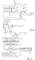
- a starter D which includes an electric motor M mounted between a terminal B + power supply to battery voltage and ground.
- Electric motor supply is controlled by a contactor 1 mounted between said terminal B + and the motor M.
- This contactor 1 is a relay which includes a plunger core (not shown) actuated by a winding call 2 and a holding coil 3 for pushing and maintain a power contact in the closed position 1a.
- the call winding 2 is mounted between the end of the motor M which is opposite to the ground and the winding 3, said coil 3 being connected to ground by its end opposite.
- the coils 2 and 3 are connected to the source of a transistor 4 whose drain is connected to terminal B +, via the ignition key switch 6.
- This transistor 4 is controlled, for example in all or nothing, by a microprocessor 5 - also connected to the supply terminal B + - which injects a voltage of control on the gate of transistor 4.
- This microprocessor 5 is for example, as illustrated in FIG. 1, integrated with relay 1 and transistor 4 inside of the starter housing. It can also be located outside the starter, anywhere in the vehicle.
- the call coil 2 is chosen with very resistance lower than that of the holding coil 3.
- the transistor 4 supplying only the coil of maintenance 3, whose current consumption is low, the heating of said transistor 4 is considerably reduced.
- the transistor 4 is then very quickly destroyed by excessive heating.
- US-A-5,345,901 describes such a device, but uses a relay instead of a transistor. To avoid overheating of the call coil of the power under the above conditions, the voltage difference between the power contact terminals is monitored and the relay is blocked if after closing the contact switch, this voltage difference is not below a predetermined threshold.
- An object of the invention is to overcome this disadvantage.
- said contactor comprising a contact power which controls the supply of the electric motor of the starter and at least one coil which controls the displacement of said contact
- said device comprising a unit for managing the starter control, as well that a transistor, controlled by said unit, which controls the supply of the contactor coil (s), characterized in that the management unit includes means to block the transistor when the fall of voltage at a point supplied with battery voltage between two successive instants following the closing of the contact switch is below a given threshold.
- the invention also relates to a device for control of the power supply of a vehicle starter automobile which comprises a contactor comprising a power contact which controls the motor supply starter motor and at least one coil which controls the movement of said contact, characterized in that that it further comprises a device for controlling contactor of the aforementioned type.
- the control device is of a structure general similar to that illustrated in Figure 1.
- the microprocessor 5 On its input which is connected to terminal B + by through the ignition key switch 6, the microprocessor 5 includes an analog converter digital which allows him to measure the voltage on terminal B + when switch 6 is closed.
- the microprocessor 5 starts the start-up process by closing the transistor 4 (step 15 on the flowchart in FIG. 3) and measures the voltage U 2 in a time T 2 following the closure of switch 6 (step 16).
- the time T 2 corresponds to approximately 10 to 20 milliseconds after the transistor 4 has switched to its on state.
- the microprocessor 5 checks the appearance of a significant voltage drop after a time T s , T s generally being between a few tenths of seconds and a few seconds.
- the microprocessor 5 checks whether or not the voltage at time T 2 + T s is greater than U 2 - dU, where dU corresponds to the expected minimum voltage drop (step 17).
- the microprocessor 5 blocks the transistor 4 to avoid its deterioration (step 18).
- microprocessor 5 continues the start-up process (step 19).
- the time T s is obviously determined so that the heating remains low enough so that the transistor 4 is not damaged.
- This solution has the advantage of allowing do not damage the power transistor 4 by a extended operation in call mode and does not require no additional components to achieve this function.
- the relay can then have only one coil instead a call coil and a holding coil.
- the device for electronic starter control illustrated in the figure 1 has the advantage of being of the "autonomous" type, that is to say not to require any other electrical connection than those used by conventional starters not electronic, namely a control cable allowing the connection with the vehicle's contact switch, a power supply cable connected to a terminal such as the positive terminal of the battery, and a return to ground by the carcass of the starter.
Landscapes
- Engineering & Computer Science (AREA)
- Chemical & Material Sciences (AREA)
- Combustion & Propulsion (AREA)
- Mechanical Engineering (AREA)
- General Engineering & Computer Science (AREA)
- Relay Circuits (AREA)
- Motor And Converter Starters (AREA)
- Electric Propulsion And Braking For Vehicles (AREA)
- Electronic Switches (AREA)
Claims (7)
- Vorrichtung zur Steuerung eines Anlaßschützes eines Kraftfahrzeuganlassers (D), wobei das besagte Anlaßschütz (1) einen Leistungskontakt (1a), der die Speisung des Elektromotors (M) des Anlassers (D) steuert, und wenigstens eine Wicklung (2, 3), die die Verstellung des besagten Kontakts (1a) steuert, umfaßt, wobei die besagte Vorrichtung eine Einheit (5) zur Regelung der Steuerung des Anlassers (D) sowie einen durch die besagte Einheit (5) kontrollierten Transistor (4) umfaßt, der die Speisung der Wicklung bzw. Wicklungen des Anlaßschützes (1) steuert, wobei die besagte Regelungseinheit (5) Mittel umfaßt, um den Transistor zu sperren, wenn der Spannungsabfall (dU) an einem mit der Batteriespannung (B+) gespeisten Punkt zwischen zwei aufeinanderfolgenden Zeitpunkten (T2 und T2 + Ts) im Anschluß an das Schließen des Zündschalters (6) kleiner als ein gegebener Schwellenwert ist.
- Vorrichtung nach Anspruch 1, dadurch gekennzeichnet, daß es sich bei der Regelungseinheit (5) um einen Mikroprozessor handelt, von dem ein Analog/Digitat-Wandler-Eingang mit dem besagten mit der Batteriespannung gespeisten Punkt verbunden ist, und daß der besagte Mikroprozessor (5) den Spannungsabfall (dU) zwischen den besagten aufeinanderfolgenden Zeitpunkten (T2 und T2 + Ts) im Anschluß an das Schließen des Zündschalters (6) bestimmt und diesen Spannungsabfall (dU) mit dem besagten Schwellenwert vergleicht.
- Vorrichtung nach einem der vorangehenden Ansprüche, dadurch gekennzeichnet, daß der Transistor (4) durch den Mikroprozessor (5) mit zwei Schaltstufen gesteuert wird.
- Vorrichtung nach einem der Ansprüche 1 oder 2, dadurch gekennzeichnet, daß der Mikroprozessor (5) den Transistor (4) so steuert, daß eine progressive Speisung der Wicklung bzw. Wicklungen des Anlaßschützes (1) herbeigeführt wird.
- Vorrichtung zur Steuerung der Speisung eines Kraftfahrzeuganlassers (D), die ein Anlaßschütz (1) mit einem Leistungskontakt (1a), der die Speisung des Elektromotors (M) des Anlassers (D) steuert, und wenigstens eine Wicklung (2, 3) umfaßt, die die Verstellung des besagten Kontakts (1a) steuert, dadurch gekennzeichnet, daß sie außerdem eine Vorrichtung zur Steuerung des Anlaßschützes (1) nach einem der vorangehenden Ansprüche umfaßt.
- Vorrichtung nach Anspruch 5, dadurch gekennzeichnet, daß das Anlaßschütz (1) eine Einzugswicklung (2) und eine Haltewicklung (3) umfaßt.
- Kraftfahrzeuganlasser, dadurch gekennzeichnet, daß er eine Vorrichtung zur Steuerung der Speisung nach Anspruch 6 enthält.
Applications Claiming Priority (2)
| Application Number | Priority Date | Filing Date | Title |
|---|---|---|---|
| FR9703089 | 1997-03-14 | ||
| FR9703089A FR2760891B1 (fr) | 1997-03-14 | 1997-03-14 | Perfectionnement aux dispositifs pour la commande d'un contacteur de demarreur de vehicule automobile |
Publications (2)
| Publication Number | Publication Date |
|---|---|
| EP0864744A1 EP0864744A1 (de) | 1998-09-16 |
| EP0864744B1 true EP0864744B1 (de) | 2002-12-11 |
Family
ID=9504778
Family Applications (1)
| Application Number | Title | Priority Date | Filing Date |
|---|---|---|---|
| EP98400553A Expired - Lifetime EP0864744B1 (de) | 1997-03-14 | 1998-03-10 | Verbesserung an Vorrichtungen zum Steuern eines Anlasschützes für einen Kraftfahrzeug |
Country Status (5)
| Country | Link |
|---|---|
| US (1) | US6011317A (de) |
| EP (1) | EP0864744B1 (de) |
| DE (1) | DE69809984T2 (de) |
| ES (1) | ES2189104T3 (de) |
| FR (1) | FR2760891B1 (de) |
Families Citing this family (4)
| Publication number | Priority date | Publication date | Assignee | Title |
|---|---|---|---|---|
| DE19612018B4 (de) | 1996-03-18 | 2005-09-29 | Dreier Technology Ag | Formmaschine |
| FR2839344B1 (fr) | 2002-03-29 | 2005-12-02 | Valeo Equip Electr Moteur | Circuit de commande electronique d'un contacteur de demarreur de vehicule automobile, equipe de moyens de correction en cas de non fermeture du contact de puissance |
| US7479711B2 (en) * | 2006-10-23 | 2009-01-20 | Ford Global Technologies, Llc | System and method for controlling cycling of a vehicle contactor |
| FR2987082B1 (fr) * | 2012-02-17 | 2015-03-13 | Valeo Equip Electr Moteur | Dispositif de demarrage d'un moteur thermique d'un vehicule automobile muni d'un systeme de mesure de tension et procede associe |
Citations (1)
| Publication number | Priority date | Publication date | Assignee | Title |
|---|---|---|---|---|
| US5345901A (en) * | 1993-07-26 | 1994-09-13 | Carrier Corporation | Starter motor protection system |
Family Cites Families (11)
| Publication number | Priority date | Publication date | Assignee | Title |
|---|---|---|---|---|
| US3893007A (en) * | 1973-07-06 | 1975-07-01 | Nippon Denso Co | Vehicle starter protective system |
| JPS5985377U (ja) * | 1982-11-30 | 1984-06-09 | 三菱電機株式会社 | エンジンのスタ−タ保護装置 |
| JPH076469B2 (ja) * | 1987-05-28 | 1995-01-30 | 三菱電機株式会社 | エンジン自動始動方法および装置 |
| US4947051A (en) * | 1988-01-22 | 1990-08-07 | Mitsubishi Denki Kabushiki Kaisha | Starter protector for an engine |
| US4917411A (en) * | 1988-12-12 | 1990-04-17 | General Motors Corporation | Electronic starting motor control with low voltage protection |
| US4906857A (en) * | 1988-12-12 | 1990-03-06 | Kikusui Line Co., Ltd. | Electronic starting motor control having fail safe and overvoltage protection |
| DE4026232C2 (de) * | 1990-08-18 | 2003-09-04 | Bosch Gmbh Robert | Einrichtung zur Überwachung eines Drehzahlgebers |
| US5459357A (en) * | 1991-08-08 | 1995-10-17 | Minks; Floyd M. | Engine operated switch for controlling operation of electrical load responsive to alternator voltage and/or battery voltage |
| US5287831A (en) * | 1991-08-15 | 1994-02-22 | Nartron Corporation | Vehicle starter and electrical system protection |
| DE19503537A1 (de) * | 1995-02-03 | 1996-08-08 | Bosch Gmbh Robert | Schaltungsanordnung für Startvorrichtung von Brennkraftmaschinen |
| US5564375A (en) * | 1995-05-15 | 1996-10-15 | Wacker Corporation | Start circuit with anti-restart circuitry |
-
1997
- 1997-03-14 FR FR9703089A patent/FR2760891B1/fr not_active Expired - Fee Related
-
1998
- 1998-03-10 ES ES98400553T patent/ES2189104T3/es not_active Expired - Lifetime
- 1998-03-10 EP EP98400553A patent/EP0864744B1/de not_active Expired - Lifetime
- 1998-03-10 DE DE69809984T patent/DE69809984T2/de not_active Expired - Lifetime
- 1998-03-13 US US09/042,169 patent/US6011317A/en not_active Expired - Lifetime
Patent Citations (1)
| Publication number | Priority date | Publication date | Assignee | Title |
|---|---|---|---|---|
| US5345901A (en) * | 1993-07-26 | 1994-09-13 | Carrier Corporation | Starter motor protection system |
Also Published As
| Publication number | Publication date |
|---|---|
| DE69809984T2 (de) | 2003-07-24 |
| US6011317A (en) | 2000-01-04 |
| FR2760891A1 (fr) | 1998-09-18 |
| ES2189104T3 (es) | 2003-07-01 |
| FR2760891B1 (fr) | 1999-05-28 |
| DE69809984D1 (de) | 2003-01-23 |
| EP0864744A1 (de) | 1998-09-16 |
Similar Documents
| Publication | Publication Date | Title |
|---|---|---|
| EP0911953B1 (de) | Regelvorrichtung für den Anlasser eines Kraftfahrzeuges | |
| FR2957386A1 (fr) | Systeme de demarrage d'un moteur a combustion interne avec fonctionnement d'un moteur electrique en modes vitesse elevee et faible | |
| EP2385538A1 (de) | Elektromagnetisches Schütz mit Doppelkontakt und damit versehener Anlasser eines Verbrennungsmotor | |
| EP2795650A1 (de) | Vorrichtung mit mehreren schützen, insbesondere zur steuerung eines elektrischen anlassers | |
| EP0796992B1 (de) | Verfahren und Vorrichtung zum Steuern eines Versorgungsschalters für einen Kraftfahrzeuganlasser | |
| FR2960265A1 (fr) | Dispositif de demarrage de moteur thermique | |
| EP1041277B1 (de) | Anlasser-Regelvorrichtung für Kraftfahrzeuge zur Verhinderung von Verschleiss | |
| EP0987434B1 (de) | Speisungsregelvorrichtung für elektrischen Anlassermotor für Verbrennungsmotor und Anlasser mit solcher Vorrichtung | |
| EP0814258B1 (de) | Abschaltsystem für Kraftfahrzeug-Anlasser | |
| EP0864744B1 (de) | Verbesserung an Vorrichtungen zum Steuern eines Anlasschützes für einen Kraftfahrzeug | |
| EP1058785B1 (de) | Steuervorrichtung für anlasser eines kraftfahrzeuges | |
| EP0864745B1 (de) | Vorrichtung zum Steuern eines Anlassschützes für einen Kraftfahrzeug | |
| FR2754016A1 (fr) | Procede et dispositif pour la commande de la coupure d'un demarreur de vehicule automobile | |
| EP0921305B1 (de) | Verfahren und Vorrichtung zur Steuerung des Stromzufuhrs einer Schalterwicklung für Kraftfahrzeuganlasser | |
| FR2870986A1 (fr) | Dispositif de commande de relais pour appareil electrique en courant continu | |
| FR2792416A1 (fr) | Procede de controle de la fin de course d'un organe mobile et dispositif pour sa mise en oeuvre | |
| EP0921306B1 (de) | Regelvorrichtung für Kraftfahrzeuganlasser | |
| WO2003083288A1 (fr) | Circuit de commande electronique d'un contacteur de demarreur de vehicule automobile. | |
| FR2802364A1 (fr) | Procede et dispositif pour la commande de l'alimentation d'un bobinage de rotor d'une machine electrique telle qu'un alternateur ou un alternateur-demarreur de vehicule, notamment automobile | |
| FR2802363A1 (fr) | Perfectionnements aux dispositifs et procedes pour la commande de l'alimentation d'un bobinage de rotor d'une machine electrique de vehicule, notamment automobile | |
| FR2843782A1 (fr) | Systeme de demarrage a organe de controle separe du demarreur | |
| FR2853018A1 (fr) | Commande du demarreur d'un moteur thermique d'un vehicule automobile | |
| EP1041276A1 (de) | Anlasser für Kraftfahrzeuge mit geringerem Verschleiss | |
| FR2896346A1 (fr) | Ensemble comprenant un coupe-circuit d'une batterie d'alimentation qui comporte un circuit electronique adapte a etre isole de la batterie d'alimentation | |
| FR2841941A1 (fr) | Demarreur a lanceur perfectionne pour un moteur a combustion interne |
Legal Events
| Date | Code | Title | Description |
|---|---|---|---|
| PUAI | Public reference made under article 153(3) epc to a published international application that has entered the european phase |
Free format text: ORIGINAL CODE: 0009012 |
|
| AK | Designated contracting states |
Kind code of ref document: A1 Designated state(s): DE ES GB IT |
|
| AX | Request for extension of the european patent |
Free format text: AL;LT;LV;MK;RO;SI |
|
| 17P | Request for examination filed |
Effective date: 19990301 |
|
| AKX | Designation fees paid |
Free format text: DE ES GB IT |
|
| RBV | Designated contracting states (corrected) |
Designated state(s): DE ES GB IT |
|
| GRAG | Despatch of communication of intention to grant |
Free format text: ORIGINAL CODE: EPIDOS AGRA |
|
| 17Q | First examination report despatched |
Effective date: 20020314 |
|
| GRAG | Despatch of communication of intention to grant |
Free format text: ORIGINAL CODE: EPIDOS AGRA |
|
| GRAH | Despatch of communication of intention to grant a patent |
Free format text: ORIGINAL CODE: EPIDOS IGRA |
|
| GRAH | Despatch of communication of intention to grant a patent |
Free format text: ORIGINAL CODE: EPIDOS IGRA |
|
| GRAA | (expected) grant |
Free format text: ORIGINAL CODE: 0009210 |
|
| AK | Designated contracting states |
Kind code of ref document: B1 Designated state(s): DE ES GB IT |
|
| REG | Reference to a national code |
Ref country code: GB Ref legal event code: FG4D Free format text: NOT ENGLISH |
|
| REF | Corresponds to: |
Ref document number: 69809984 Country of ref document: DE Date of ref document: 20030123 |
|
| PGFP | Annual fee paid to national office [announced via postgrant information from national office to epo] |
Ref country code: GB Payment date: 20030304 Year of fee payment: 6 |
|
| GBT | Gb: translation of ep patent filed (gb section 77(6)(a)/1977) |
Effective date: 20030219 |
|
| PGFP | Annual fee paid to national office [announced via postgrant information from national office to epo] |
Ref country code: ES Payment date: 20030314 Year of fee payment: 6 |
|
| REG | Reference to a national code |
Ref country code: ES Ref legal event code: FG2A Ref document number: 2189104 Country of ref document: ES Kind code of ref document: T3 |
|
| PLBE | No opposition filed within time limit |
Free format text: ORIGINAL CODE: 0009261 |
|
| STAA | Information on the status of an ep patent application or granted ep patent |
Free format text: STATUS: NO OPPOSITION FILED WITHIN TIME LIMIT |
|
| 26N | No opposition filed |
Effective date: 20030912 |
|
| PG25 | Lapsed in a contracting state [announced via postgrant information from national office to epo] |
Ref country code: GB Free format text: LAPSE BECAUSE OF NON-PAYMENT OF DUE FEES Effective date: 20040310 |
|
| PG25 | Lapsed in a contracting state [announced via postgrant information from national office to epo] |
Ref country code: ES Free format text: LAPSE BECAUSE OF NON-PAYMENT OF DUE FEES Effective date: 20040311 |
|
| GBPC | Gb: european patent ceased through non-payment of renewal fee |
Effective date: 20040310 |
|
| REG | Reference to a national code |
Ref country code: ES Ref legal event code: FD2A Effective date: 20040311 |
|
| PGFP | Annual fee paid to national office [announced via postgrant information from national office to epo] |
Ref country code: IT Payment date: 20080328 Year of fee payment: 11 |
|
| PG25 | Lapsed in a contracting state [announced via postgrant information from national office to epo] |
Ref country code: IT Free format text: LAPSE BECAUSE OF NON-PAYMENT OF DUE FEES Effective date: 20090310 |
|
| PGFP | Annual fee paid to national office [announced via postgrant information from national office to epo] |
Ref country code: DE Payment date: 20110310 Year of fee payment: 14 |
|
| REG | Reference to a national code |
Ref country code: DE Ref legal event code: R119 Ref document number: 69809984 Country of ref document: DE Effective date: 20121002 |
|
| PG25 | Lapsed in a contracting state [announced via postgrant information from national office to epo] |
Ref country code: DE Free format text: LAPSE BECAUSE OF NON-PAYMENT OF DUE FEES Effective date: 20121002 |