EP0864751A2 - Kompressor zur Verwendung in einem überkritischen Kältekreislaufsystem - Google Patents
Kompressor zur Verwendung in einem überkritischen Kältekreislaufsystem Download PDFInfo
- Publication number
- EP0864751A2 EP0864751A2 EP98301867A EP98301867A EP0864751A2 EP 0864751 A2 EP0864751 A2 EP 0864751A2 EP 98301867 A EP98301867 A EP 98301867A EP 98301867 A EP98301867 A EP 98301867A EP 0864751 A2 EP0864751 A2 EP 0864751A2
- Authority
- EP
- European Patent Office
- Prior art keywords
- compressor
- lubricating oil
- housing
- pressure fluid
- pressure
- Prior art date
- Legal status (The legal status is an assumption and is not a legal conclusion. Google has not performed a legal analysis and makes no representation as to the accuracy of the status listed.)
- Withdrawn
Links
- 238000005057 refrigeration Methods 0.000 title claims abstract description 28
- 239000010687 lubricating oil Substances 0.000 claims abstract description 74
- 239000003507 refrigerant Substances 0.000 claims abstract description 64
- 239000012530 fluid Substances 0.000 claims abstract description 25
- 239000003921 oil Substances 0.000 claims description 27
- 238000007599 discharging Methods 0.000 claims description 2
- CURLTUGMZLYLDI-UHFFFAOYSA-N Carbon dioxide Chemical compound O=C=O CURLTUGMZLYLDI-UHFFFAOYSA-N 0.000 description 10
- 239000007788 liquid Substances 0.000 description 8
- KYKAJFCTULSVSH-UHFFFAOYSA-N chloro(fluoro)methane Chemical compound F[C]Cl KYKAJFCTULSVSH-UHFFFAOYSA-N 0.000 description 7
- 230000006835 compression Effects 0.000 description 7
- 238000007906 compression Methods 0.000 description 7
- 229910002092 carbon dioxide Inorganic materials 0.000 description 6
- 239000001569 carbon dioxide Substances 0.000 description 6
- 238000010276 construction Methods 0.000 description 6
- 238000005461 lubrication Methods 0.000 description 4
- 238000004519 manufacturing process Methods 0.000 description 3
- 239000000203 mixture Substances 0.000 description 3
- 230000002159 abnormal effect Effects 0.000 description 2
- 230000001050 lubricating effect Effects 0.000 description 2
- 230000001737 promoting effect Effects 0.000 description 2
- 238000012986 modification Methods 0.000 description 1
- 230000004048 modification Effects 0.000 description 1
- 230000002093 peripheral effect Effects 0.000 description 1
- 239000010726 refrigerant oil Substances 0.000 description 1
- 229920006395 saturated elastomer Polymers 0.000 description 1
- 238000000926 separation method Methods 0.000 description 1
- 239000007921 spray Substances 0.000 description 1
Images

Classifications
-
- F—MECHANICAL ENGINEERING; LIGHTING; HEATING; WEAPONS; BLASTING
- F04—POSITIVE - DISPLACEMENT MACHINES FOR LIQUIDS; PUMPS FOR LIQUIDS OR ELASTIC FLUIDS
- F04B—POSITIVE-DISPLACEMENT MACHINES FOR LIQUIDS; PUMPS
- F04B39/00—Component parts, details, or accessories, of pumps or pumping systems specially adapted for elastic fluids, not otherwise provided for in, or of interest apart from, groups F04B25/00 - F04B37/00
- F04B39/02—Lubrication
-
- F—MECHANICAL ENGINEERING; LIGHTING; HEATING; WEAPONS; BLASTING
- F04—POSITIVE - DISPLACEMENT MACHINES FOR LIQUIDS; PUMPS FOR LIQUIDS OR ELASTIC FLUIDS
- F04B—POSITIVE-DISPLACEMENT MACHINES FOR LIQUIDS; PUMPS
- F04B27/00—Multi-cylinder pumps specially adapted for elastic fluids and characterised by number or arrangement of cylinders
- F04B27/08—Multi-cylinder pumps specially adapted for elastic fluids and characterised by number or arrangement of cylinders having cylinders coaxial with, or parallel or inclined to, main shaft axis
- F04B27/10—Multi-cylinder pumps specially adapted for elastic fluids and characterised by number or arrangement of cylinders having cylinders coaxial with, or parallel or inclined to, main shaft axis having stationary cylinders
- F04B27/1036—Component parts, details, e.g. sealings, lubrication
-
- F—MECHANICAL ENGINEERING; LIGHTING; HEATING; WEAPONS; BLASTING
- F25—REFRIGERATION OR COOLING; COMBINED HEATING AND REFRIGERATION SYSTEMS; HEAT PUMP SYSTEMS; MANUFACTURE OR STORAGE OF ICE; LIQUEFACTION SOLIDIFICATION OF GASES
- F25B—REFRIGERATION MACHINES, PLANTS OR SYSTEMS; COMBINED HEATING AND REFRIGERATION SYSTEMS; HEAT PUMP SYSTEMS
- F25B2309/00—Gas cycle refrigeration machines
- F25B2309/06—Compression machines, plants or systems characterised by the refrigerant being carbon dioxide
- F25B2309/061—Compression machines, plants or systems characterised by the refrigerant being carbon dioxide with cycle highest pressure above the supercritical pressure
-
- F—MECHANICAL ENGINEERING; LIGHTING; HEATING; WEAPONS; BLASTING
- F25—REFRIGERATION OR COOLING; COMBINED HEATING AND REFRIGERATION SYSTEMS; HEAT PUMP SYSTEMS; MANUFACTURE OR STORAGE OF ICE; LIQUEFACTION SOLIDIFICATION OF GASES
- F25B—REFRIGERATION MACHINES, PLANTS OR SYSTEMS; COMBINED HEATING AND REFRIGERATION SYSTEMS; HEAT PUMP SYSTEMS
- F25B9/00—Compression machines, plants or systems, in which the refrigerant is air or other gas of low boiling point
- F25B9/002—Compression machines, plants or systems, in which the refrigerant is air or other gas of low boiling point characterised by the refrigerant
- F25B9/008—Compression machines, plants or systems, in which the refrigerant is air or other gas of low boiling point characterised by the refrigerant the refrigerant being carbon dioxide
Definitions
- This invention relates to a compressor for use in a transcritical refrigeration cycle system, and more particularly to a compressor of this kind having a construction which is capable of promoting lubrication of sliding contact members within the compressor so as to prevent seizure or wear of the components.
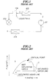
- FIG. 1 shows a refrigeration cycle system using a chlorofluorocarbon as a refrigerant
- FIG. 2 is a Mollier chart of the chlorofluorocarbon.
- Reference numerals (1) to (4) in FIG. 1 correspond to reference numerals (1) to (4) in FIG. 2, respectively.
- the refrigerant in a gaseous state is compressed within a compressor 201 into high-pressure and high-temperature refrigerant gas ((1) to (2) in FIG. 2), which is discharged from the compressor 201 via a discharge port of the same and flows into a condenser 202. Then, the high-pressure and high-temperature refrigerant gas is cooled in the condenser 202 due to a difference in temperature between the refrigerant gas and the air outside the condenser 202, to be transformed from a gaseous state to a liquid state ((2) to (3) in FIG. 2).
- the liquefied refrigerant flows to an expansion valve 203 via a liquid tank 206.
- the expansion valve 203 the liquefied high-pressure refrigerant gas is drastically expanded and changed into atomized low-pressure and low-temperature refrigerant ((3) to (4) in FIG. 2).
- the atomized low-pressure and low-temperature refrigerant gas flows into an evaporator 204 and absorbs heat from air surrounding the evaporator 204 to completely vaporize, followed by returning into the compressor 201 in a gaseous state ((4) to (1) in FIG. 2).
- Lubricating oil contained in the refrigerant gas flows out of the compressor 201 via the discharge port of the same together with the refrigerant gas, and dissolves into the liquefied refrigerant within the condenser 202.
- the liquid mixture of the lubricating oil and the liquefied refrigerant gas is far less viscous than the lubricating oil itself, and the lubricating oil and the liquefied refrigerant are uniformly blended with each other in the mixture, which inhibits the lubricating oil from affecting a flow of the refrigerant within the expansion valve 203. Further, since the lubricating oil and the refrigerant flow into the expansion valve 203 in a state of liquid mixture, it is easy to set a degree of throttling or restriction of the expansion valve 203.
- a transcritical refrigeration cycle system in which e.g. carbon dioxide is used as a refrigerant has a high-pressure line between the discharge port of a compressor and the inlet port of an expansion valve as a transcritical zone in which refrigerant gas is not condensed (see FIG. 6 Mollier chart).
- the lubricating oil having a high viscosity increases resistance to the flow of the refrigerant gas, whereby pressure within the high-pressure line between the discharge port of the compressor and the inlet port of the expansion valve is increased. As a result, discharge pressure/temperature within the compressor is increased, and at the same time, the amount of lubricating oil returned to the compressor becomes insufficient, which causes seizure or wear of sliding contact members within the compressor.
- the pressure level of the refrigerant gas is approximately ten times higher than that of the chlorofluorocarbon used in the typical refrigeration cycle system, so that high pressure acts on surfaces of the sliding contact members within the compressor, and a PV value (quantity of gas) is also increased.
- The is requires the housing of the compressor and the sliding contact members within the same to have high rigidity and strength.
- a further problem is that mechanical seals, which are provided as a shaft seal between the housing and a drive shaft so as to prevent leakage of refrigerant gas into the atmosphere, easily wear out if the supply of lubricating oil to the mechanical seals is insufficient.
- a compressor for use in a transcritical refrigeration cycle system including a housing, a drive shaft, a bearing arranged within the housing, for rotatably supporting the drive shaft, a shaft seal interposed between the housing and the drive shaft so as to prevent a high-pressure fluid essentially consisting of a refrigerant and a lubricating oil from leaking out of the compressor, a space in which are received the bearing and the shaft seal, and a discharge port via which the high-pressure fluid in discharged from the compressor, wherein pressure within the space is lower than discharge pressure.
- the compressor according to the first aspect of the invention is characterized by comprising a lubricating oil return passage formed through the housing, for returning the lubricating oil separated from the high-pressure fluid discharged from the discharge of the compressor port to the space within the compressor.
- the transcritical refrigeration cycle system includes an oil separator for separating out the lubricating oil from the high-pressure fluid, the oil separator having an oil outlet port, and a lubricating oil return line extends from the oil outlet of the oil separator, and the lubricating oil return passage has an inlet port thereof connected to the lubricating oil return line.
- the transcritical refrigeration cycle system including the compressor is not required to have a complicated construction, which makes it possible to prevent manufacturing costs thereof from being increased.
- the lubricating oil return passage is formed through an upper wall of the housing, for communicating with the space.
- the compressor since lubricating oil returned via the lubricating oil return passage is sprayed directly onto the bearing and the shaft seal within the space, the compressor is not required to have a device for drawing up lubricating oil collected in a lower portion within the compressor, so that complication of the construction of the compressor can be avoided.
- a transcritical refrigeration system comprising:
- the compressor includes a drive shaft, a bearing arranged within the housing, for rotatably supporting the drive shaft, a shaft seal interposed between the housing and the drive shaft so as to prevent the high-pressure fluid from leaking out of the compressor, and a space in which are received the bearing and the shaft seal, and the lubricating oil return passage communicates with the space.
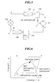
- FIG. 5 shows a transcritical refrigeration cycle system including a compressor according to an embodiment of the invention
- FIG. 6 shows a Mollier chart of carbon dioxide.
- Reference numerals (1) to (4) in FIG. 5 correspond to reference numerals (1) to (4) in FIG. 6.
- the transcritical refrigeration cycle system in which e.g. carbon dioxide (CO 2 ) is used as refrigerant gas includes the compressor 101, an oil separator 106, a cooler 102, an expansion valve 103, an evaporator 104, and a liquid tank (accumulator) 105.
- the oil separator 106 is arranged between the compressor 101 and the cooler 102.
- Refrigerant gas is compressed within the compressor 101 into high-pressure and high-temperature refrigerant gas ((1) to (2) in FIG. 6), and discharged from the compressor 101 as a high-pressure fluid containing lubricating oil via a discharge port 3a of the same to flow into to the oil separator 106.
- lubricating oil is separated from the refrigerant gas.
- the separated lubricating oil is returned to the compressor 101 via a lubricating oil return line C (communicating between an outlet port of the oil separator 106 and an inlet port 50a of a lubricating oil return passage 50 formed in the compressor 101), while the refrigerant gas is delivered to the cooler 102 along a high-pressure line A (extending between the discharge port 3a of the compressor 101 and an inlet port of the expansion valve 103).
- a high-pressure line A extending between the discharge port 3a of the compressor 101 and an inlet port of the expansion valve 103.
- the refrigerant gas is cooled due to the difference in temperature between the refrigerant gas and air outside the cooler. However, since the refrigerant gas is in a transcritical zone, it is not condensed ((2) to (3) in FIG. 2).
- the refrigerant gas flows from the cooler 102 to the expansion valve 103 in a state in which it is not liquefied (i.e. in a state of high-density gas).
- the expansion valve 103 the high-pressure refrigerant gas is drastically expanded and changed into low-pressure and low-temperature refrigerant gas.
- the refrigerant gas becomes saturated and is liquefied for the first time ((3) to (4) in FIG. 6).
- the low-pressure and low-temperature refrigerant gas flows from the expansion valve 103 to the evaporator 104 along a low-pressure line B (extending between the outlet port of the expansion valve 103 and a suction port of the compressor 101) and absorbs heat from air surrounding the evaporator 104 to completely vaporize ((4) to (1) in FIG. 6).
- the evaporator 104 has an outlet port thereof connected to the liquid tank 105.
- the refrigerant gas is separated into gaseous refrigerant and liquid refrigerant in the liquid tank 105, followed by the gaseous refrigerant being drawn into the compressor 101 via the suction port of the same.
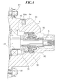
- FIG. 3 shows the whole arrangement of the compressor according to the embodiment of the invention.
- FIG. 4 shows essential parts of the FIG. 3 compressor on an enlarged scale.
- the internal construction of the compressor is schematically shown, and hence component parts such as a swash plate are not illustrated in detail.
- the compressor 101 for use within the transcritical refrigeration cycle system has a cylinder block 1 having one end thereof secured to a rear head 3 via a valve plate 2 and the other end thereof secured to a front head (housing) 4.
- the cylinder block 1, the rear head 3, and the front head 4 are tightened in a longitudinal direction by through bolts 80, 81.
- the cylinder block 1 has a plurality of cylinder bores 6 axially extending therethrough at predetermined circumferential intervals about a drive shaft 5.
- Each cylinder bore 6 has a piston 7 slidably received therein.
- the front head 4 defines a crankcase 8 in which a swash plate 10 is received.
- the swash plate 10 is fixedly fitted on the drive shaft 5.
- the swash plate 10 has an inclined surface 10a which is inclined at a predetermined angle with respect to an imaginary plane orthogonal to the drive shaft 5.
- the length of stroke of each piston 7 is determined according to the predetermined inclination angle of the inclined surface 10a of the swash plate 10.
- the swash plate 10 has a vertical surface 10b orthogonal to the drive shaft 10.
- the vertical surface 10b of the swash plate 10 is rotatably supported on an inner wall surface of the front head 4 by a thrust bearing 33.
- Each connecting rod 11 has one end thereof secured to a corresponding one of the pistons 7 and the other end 11a, spherical in shape, connected to the inclined surface 10a of the swash plate 10 such that it slides on the inclined surface 10a to the swash plate 10.
- the drive shaft 5 has a rear end thereof rotatably supported by a radial bearing 26 within the cylinder block 1, and an intermediate portion thereof rotatably supported by a radial bearing (bearing) 24 within the front head 4.
- Mechanical seals (shaft seal) 30, 31 are interposed between an inner peripheral wall of the front head 4 and a front-end portion of the drive shaft 5.
- a space 40 in which are received the radial bearing 24 and the mechanical seals 30, 31 is communicated with the crankcase 8.
- the mechanical seal 30 is fixed to the front head 4, using dowels 90 for properly positioning the mechanical seal 30, while the mechanical seal 31 is rigidly fitted on the drive shaft 5.
- a rear end face of the mechanical seal 30 and a front end face of the mechanical seal 31 are in intimate contact with each other in an axial direction.
- the front head 4 has an upper wall portion 4a formed therethrough with the lubricating oil return passage 50 which communicates with the space 40.
- the lubricating oil return line C is connected to the inlet port 50a of the passage 50.
- the valve plate 2 is formed with refrigerant outlet ports 16 for each communicating between a compression chamber within a corresponding one of the cylinder bores 6 and the discharge chamber 12, and refrigerant inlet ports 15 for each communicating between a compression chamber within a corresponding one of the cylinder bores 6 and the suction chamber 13.
- the refrigerant outlet ports 16 and the refrigerant inlet ports 15 are arranged at predetermined circumferential intervals about the drive shaft 5.
- Each refrigerant outlet port 16 is opened and closed by a discharge valve 17.
- the discharge valve 17 is fixed to a rear head-side end face of the valve plate 2 by a bolt 19 and a nut 20 together with a valve stopper 18.
- each refrigerant inlet port 15 is opened and closed by a suction valve 21 arranged between the valve plate 2 and the cylinder block 1.
- a communication passage 60 is formed through the cylinder block 1 to connect between the suction chamber 13 and the crankcase 8.
- Torque of an engine, not shown, installed on an automotive vehicle, not shown, is transmitted to the drive shaft 5 to rotate the same.
- the swash plate 10 rotates in unison with the drive shaft 5.
- the rotation of the swash plate 10 causes the spherical end 11a of each of the connecting rods 11 to slide on the inclined surface 10a of the swash plate 10, whereby the torque transmitted from the swash plate 10 is converted into the reciprocating motion of the piston 7.
- the piston 7 reciprocates within the cylinder bore 6, the volume of the compression chamber within the cylinder bore 6 changes.
- suction, compression and delivery of refrigerant gas are sequentially carried out in the compression chamber.
- the suction valve 21 opens to draw low-pressure refrigerant gas from the suction chamber 13 into the compression chamber within the cylinder bore 6, while during the discharge stroke of the same, the discharge valve 17 opens to deliver high-pressure refrigerant gas from the compression chamber to the discharge chamber 12.
- the refrigerant gas delivered to the discharge chamber 12 is discharged from the compressor 101 via the discharge port 3a together with lubricating oil contained therein (i.e. as the high-pressure fluid essentially consisting of refrigerant and lubricating oil), and then flows into the oil separator 106, in which the refrigerant gas and the lubricating oil are separated from each other. After having undergone the oil separation, the refrigerant gas flows to the cooler 102 along the high-pressure line A.
- lubricating oil contained therein i.e. as the high-pressure fluid essentially consisting of refrigerant and lubricating oil
- Pressure (discharge pressure) within the discharge port 3a is higher than pressure within the space 40, so that the lubricating oil separated from the refrigerant gas within the oil separator 106 is returned to the compressor 101 via the lubricating oil return line C.
- the lubricating oil returned to the compressor 101 is supplied to the space 40 via the lubricating oil return passage 50 to lubricate the radial bearing 24 and the mechanical seals 30, 31.
- the degree of throttling or restriction of the expansion valve 103 can be set easily.
- a lubricating oil-feeding device such as a lubricating oil pump (e.g. a trochoid pump) can be dispensed with. Therefore, the transcritical refrigeration cycle system including the compressor is not required to have a complicated construction, which makes it possible to prevent manufacturing costs thereof from being increased.
- the lubricating oil return passage 50 is formed through the upper wall portion 4a of the front head 4 so as to spray lubricating oil directly on the radial bearing 24 and the mechanical seals 30, 31, it is not necessary to provide the compressor with a device for drawing up lubricating oil collected in a portion within the compressor. This advantageously makes it possible to avoid complication of the construction of the compressor to thereby prevent manufacturing costs of the compressor from being increased.
Landscapes
- Engineering & Computer Science (AREA)
- Mechanical Engineering (AREA)
- General Engineering & Computer Science (AREA)
- Compressor (AREA)
- Applications Or Details Of Rotary Compressors (AREA)
- Compressors, Vaccum Pumps And Other Relevant Systems (AREA)
Applications Claiming Priority (2)
| Application Number | Priority Date | Filing Date | Title |
|---|---|---|---|
| JP9076573A JPH10253177A (ja) | 1997-03-12 | 1997-03-12 | 遷臨界冷凍サイクル用圧縮機 |
| JP76573/97 | 1997-03-12 |
Publications (2)
| Publication Number | Publication Date |
|---|---|
| EP0864751A2 true EP0864751A2 (de) | 1998-09-16 |
| EP0864751A3 EP0864751A3 (de) | 1999-04-21 |
Family
ID=13608996
Family Applications (1)
| Application Number | Title | Priority Date | Filing Date |
|---|---|---|---|
| EP98301867A Withdrawn EP0864751A3 (de) | 1997-03-12 | 1998-03-12 | Kompressor zur Verwendung in einem überkritischen Kältekreislaufsystem |
Country Status (2)
| Country | Link |
|---|---|
| EP (1) | EP0864751A3 (de) |
| JP (1) | JPH10253177A (de) |
Cited By (5)
| Publication number | Priority date | Publication date | Assignee | Title |
|---|---|---|---|---|
| EP0942169A3 (de) * | 1998-03-09 | 2000-02-23 | Kabushiki Kaisha Toyoda Jidoshokki Seisakusho | Kurbelkammerdruckregelung für einen Schrägscheibenverdichter |
| EP1795750A1 (de) * | 2005-12-07 | 2007-06-13 | Kabushiki Kaisha Toyoda Jidoshokki | Kolbenverdichter |
| CN107100827A (zh) * | 2017-05-03 | 2017-08-29 | 江苏昊科汽车空调有限公司 | 一种具有自润滑功能的车载空调压缩机 |
| WO2020052141A1 (zh) * | 2018-09-14 | 2020-03-19 | 珠海格力电器股份有限公司 | 喷液环和制冷剂润滑轴承组件 |
| CN115628192A (zh) * | 2022-09-29 | 2023-01-20 | 燕山大学 | 具有监测轴向位移功能的超高压泵泵芯 |
Families Citing this family (6)
| Publication number | Priority date | Publication date | Assignee | Title |
|---|---|---|---|---|
| EP1206656B1 (de) * | 1999-08-06 | 2005-01-05 | LuK Fahrzeug-Hydraulik GmbH & Co. KG | Co 2 - kompressor |
| JP2001107850A (ja) * | 1999-10-12 | 2001-04-17 | Zexel Valeo Climate Control Corp | 斜板式冷媒圧縮機 |
| JP2009257131A (ja) * | 2008-04-14 | 2009-11-05 | Valeo Thermal Systems Japan Corp | 圧縮機の潤滑剤供給構造 |
| WO2010126965A2 (en) | 2009-04-30 | 2010-11-04 | Tsc Offshore Group Limited | Pump liner retention device |
| JP4859952B2 (ja) * | 2009-05-18 | 2012-01-25 | 三菱重工業株式会社 | 開放型圧縮機 |
| JP6758963B2 (ja) * | 2016-07-07 | 2020-09-23 | 三菱重工サーマルシステムズ株式会社 | 冷凍装置 |
Family Cites Families (7)
| Publication number | Priority date | Publication date | Assignee | Title |
|---|---|---|---|---|
| GB191110243A (en) * | 1911-04-27 | 1911-10-26 | Wendelin Voelker | Devices for Continously and Automatically Lubricating all Parts to be Lubricated in Compressors of Frigorific Machines or the like. |
| GB237323A (en) * | 1924-03-28 | 1925-07-28 | Henry Selby Hele Shaw | Improvements in rotary air compressors |
| US3062020A (en) * | 1960-11-18 | 1962-11-06 | Gen Motors Corp | Refrigerating apparatus with compressor output modulating means |
| US3738118A (en) * | 1972-01-31 | 1973-06-12 | Gen Motors Corp | Means for lubricating vehicle air conditioning compressor shaft seals |
| DE2626860A1 (de) * | 1976-06-16 | 1977-12-29 | Frenzel Gmbh & Co | Kolbenverdichter fuer eine anlage zur kaelteerzeugung |
| CA1100319A (en) * | 1979-05-10 | 1981-05-05 | Eugene E. Young | Oil return system and method |
| JPS59180080A (ja) * | 1983-03-29 | 1984-10-12 | Nippon Denso Co Ltd | 自動車空調装置用コンプレツサ |
-
1997
- 1997-03-12 JP JP9076573A patent/JPH10253177A/ja active Pending
-
1998
- 1998-03-12 EP EP98301867A patent/EP0864751A3/de not_active Withdrawn
Non-Patent Citations (1)
| Title |
|---|
| None |
Cited By (7)
| Publication number | Priority date | Publication date | Assignee | Title |
|---|---|---|---|---|
| EP0942169A3 (de) * | 1998-03-09 | 2000-02-23 | Kabushiki Kaisha Toyoda Jidoshokki Seisakusho | Kurbelkammerdruckregelung für einen Schrägscheibenverdichter |
| US6280151B1 (en) | 1998-03-09 | 2001-08-28 | Kabushiki Kaisha Toyoda Jidoshokki Seisakusho | Single-ended swash plate compressor |
| EP1795750A1 (de) * | 2005-12-07 | 2007-06-13 | Kabushiki Kaisha Toyoda Jidoshokki | Kolbenverdichter |
| CN107100827A (zh) * | 2017-05-03 | 2017-08-29 | 江苏昊科汽车空调有限公司 | 一种具有自润滑功能的车载空调压缩机 |
| WO2020052141A1 (zh) * | 2018-09-14 | 2020-03-19 | 珠海格力电器股份有限公司 | 喷液环和制冷剂润滑轴承组件 |
| US11473625B2 (en) | 2018-09-14 | 2022-10-18 | Gree Electric Appliances, Inc. Of Zhuhai | Liquid injection ring and refrigerant lubricated bearing assembly |
| CN115628192A (zh) * | 2022-09-29 | 2023-01-20 | 燕山大学 | 具有监测轴向位移功能的超高压泵泵芯 |
Also Published As
| Publication number | Publication date |
|---|---|
| JPH10253177A (ja) | 1998-09-25 |
| EP0864751A3 (de) | 1999-04-21 |
Similar Documents
| Publication | Publication Date | Title |
|---|---|---|
| US6183211B1 (en) | Two stage oil free air compressor | |
| US6296457B1 (en) | Discharge pulsation damping apparatus for compressor | |
| EP0864751A2 (de) | Kompressor zur Verwendung in einem überkritischen Kältekreislaufsystem | |
| US4019342A (en) | Compressor for a refrigerant gas | |
| US20120234038A1 (en) | Compressor | |
| JP2024059907A (ja) | 非改良スクロールコンプレッサを備えたヘリウムコンプレッサシステム | |
| US5784950A (en) | Single headed swash plate type compressor having a piston with an oil communication hole on a side of the piston remote from the cylinder bore and crank chamber | |
| CA2441052C (en) | Horizontal two stage rotary compressor with improved lubrication structure | |
| US5997257A (en) | Refrigerant compressor | |
| CN106194735B (zh) | 旋转压缩机及具有其的制冷循环装置 | |
| US6095761A (en) | Swash plate compressor | |
| US6019027A (en) | Refrigerant compressor | |
| EP0864787A2 (de) | Kompressordichtung zur Verwendung in einem überkritischen Kältekreislaufsystem | |
| US5152673A (en) | Fluid pumping assembly having a control valve boss fluid by-pass | |
| US5167492A (en) | Fluid pumping assembly having a lubrication circuit functioning independent of the orientation of the fluid pumping assembly | |
| JP6898468B2 (ja) | 往復動圧縮機 | |
| US7178450B1 (en) | Sealing system for a compressor | |
| JP2002005020A (ja) | 冷媒圧縮機 | |
| JP2715553B2 (ja) | 斜板式圧縮機 | |
| JP2641479B2 (ja) | 可変容量式斜板型圧縮機 | |
| US20250320870A1 (en) | Rotary compressor and refrigeration apparatus | |
| JPH10220355A (ja) | 斜板型圧縮機 | |
| JPS593197Y2 (ja) | ピストン式冷媒圧縮機 | |
| JP3666170B2 (ja) | 斜板型圧縮機 | |
| JPH11230032A (ja) | 斜板式圧縮機 |
Legal Events
| Date | Code | Title | Description |
|---|---|---|---|
| PUAI | Public reference made under article 153(3) epc to a published international application that has entered the european phase |
Free format text: ORIGINAL CODE: 0009012 |
|
| AK | Designated contracting states |
Kind code of ref document: A2 Designated state(s): DE FR GB |
|
| AX | Request for extension of the european patent |
Free format text: AL;LT;LV;MK;RO;SI |
|
| PUAL | Search report despatched |
Free format text: ORIGINAL CODE: 0009013 |
|
| AK | Designated contracting states |
Kind code of ref document: A3 Designated state(s): AT BE CH DE DK ES FI FR GB GR IE IT LI LU MC NL PT SE |
|
| AX | Request for extension of the european patent |
Free format text: AL;LT;LV;MK;RO;SI |
|
| 17P | Request for examination filed |
Effective date: 19990813 |
|
| AKX | Designation fees paid |
Free format text: DE FR GB |
|
| RAP1 | Party data changed (applicant data changed or rights of an application transferred) |
Owner name: BOSCH AUTOMOTIVE SYSTEMS CORPORATION |
|
| RAP1 | Party data changed (applicant data changed or rights of an application transferred) |
Owner name: ZEXEL VALEO CLIMATE CONTROL CORPORATION |
|
| 17Q | First examination report despatched |
Effective date: 20030430 |
|
| STAA | Information on the status of an ep patent application or granted ep patent |
Free format text: STATUS: THE APPLICATION IS DEEMED TO BE WITHDRAWN |
|
| 18D | Application deemed to be withdrawn |
Effective date: 20030911 |