EP0864844B1 - Brückenzünder für Explosivstoffe und Verfahren zum Herstellen eines solchen Zünders - Google Patents
Brückenzünder für Explosivstoffe und Verfahren zum Herstellen eines solchen Zünders Download PDFInfo
- Publication number
- EP0864844B1 EP0864844B1 EP98104279A EP98104279A EP0864844B1 EP 0864844 B1 EP0864844 B1 EP 0864844B1 EP 98104279 A EP98104279 A EP 98104279A EP 98104279 A EP98104279 A EP 98104279A EP 0864844 B1 EP0864844 B1 EP 0864844B1
- Authority
- EP
- European Patent Office
- Prior art keywords
- exothermic
- circuit board
- holes
- instrument
- resist layer
- Prior art date
- Legal status (The legal status is an assumption and is not a legal conclusion. Google has not performed a legal analysis and makes no representation as to the accuracy of the status listed.)
- Expired - Lifetime
Links
Images

Classifications
-
- F—MECHANICAL ENGINEERING; LIGHTING; HEATING; WEAPONS; BLASTING
- F42—AMMUNITION; BLASTING
- F42B—EXPLOSIVE CHARGES, e.g. FOR BLASTING, FIREWORKS, AMMUNITION
- F42B3/00—Blasting cartridges, i.e. case and explosive
- F42B3/10—Initiators therefor
- F42B3/12—Bridge initiators
- F42B3/121—Initiators with incorporated integrated circuit
-
- F—MECHANICAL ENGINEERING; LIGHTING; HEATING; WEAPONS; BLASTING
- F42—AMMUNITION; BLASTING
- F42B—EXPLOSIVE CHARGES, e.g. FOR BLASTING, FIREWORKS, AMMUNITION
- F42B3/00—Blasting cartridges, i.e. case and explosive
- F42B3/10—Initiators therefor
- F42B3/195—Manufacture
- F42B3/198—Manufacture of electric initiator heads e.g., testing, machines
-
- Y—GENERAL TAGGING OF NEW TECHNOLOGICAL DEVELOPMENTS; GENERAL TAGGING OF CROSS-SECTIONAL TECHNOLOGIES SPANNING OVER SEVERAL SECTIONS OF THE IPC; TECHNICAL SUBJECTS COVERED BY FORMER USPC CROSS-REFERENCE ART COLLECTIONS [XRACs] AND DIGESTS
- Y10—TECHNICAL SUBJECTS COVERED BY FORMER USPC
- Y10S—TECHNICAL SUBJECTS COVERED BY FORMER USPC CROSS-REFERENCE ART COLLECTIONS [XRACs] AND DIGESTS
- Y10S428/00—Stock material or miscellaneous articles
- Y10S428/901—Printed circuit
-
- Y—GENERAL TAGGING OF NEW TECHNOLOGICAL DEVELOPMENTS; GENERAL TAGGING OF CROSS-SECTIONAL TECHNOLOGIES SPANNING OVER SEVERAL SECTIONS OF THE IPC; TECHNICAL SUBJECTS COVERED BY FORMER USPC CROSS-REFERENCE ART COLLECTIONS [XRACs] AND DIGESTS
- Y10—TECHNICAL SUBJECTS COVERED BY FORMER USPC
- Y10T—TECHNICAL SUBJECTS COVERED BY FORMER US CLASSIFICATION
- Y10T428/00—Stock material or miscellaneous articles
- Y10T428/24—Structurally defined web or sheet [e.g., overall dimension, etc.]
- Y10T428/24802—Discontinuous or differential coating, impregnation or bond [e.g., artwork, printing, retouched photograph, etc.]
- Y10T428/24917—Discontinuous or differential coating, impregnation or bond [e.g., artwork, printing, retouched photograph, etc.] including metal layer
-
- Y—GENERAL TAGGING OF NEW TECHNOLOGICAL DEVELOPMENTS; GENERAL TAGGING OF CROSS-SECTIONAL TECHNOLOGIES SPANNING OVER SEVERAL SECTIONS OF THE IPC; TECHNICAL SUBJECTS COVERED BY FORMER USPC CROSS-REFERENCE ART COLLECTIONS [XRACs] AND DIGESTS
- Y10—TECHNICAL SUBJECTS COVERED BY FORMER USPC
- Y10T—TECHNICAL SUBJECTS COVERED BY FORMER US CLASSIFICATION
- Y10T428/00—Stock material or miscellaneous articles
- Y10T428/24—Structurally defined web or sheet [e.g., overall dimension, etc.]
- Y10T428/24802—Discontinuous or differential coating, impregnation or bond [e.g., artwork, printing, retouched photograph, etc.]
- Y10T428/24926—Discontinuous or differential coating, impregnation or bond [e.g., artwork, printing, retouched photograph, etc.] including ceramic, glass, porcelain or quartz layer
Definitions
- the present invention relates to an exothermic instrument for firing an explosive used to fire a squib loaded, for example, with powder and a circuit board used for such an exothermic instrument as well as to a manufacturing method of the circuit board.
- the gas generator has an squib and gas a generating agent, for example, the mixture of sodium azide and metal oxide with nitrate or perchlorate and reducing agent.
- the squib incorporates an exothermic instrument comprising an exothermic resistance and electrode pins communicating therewith, and an explosive. When an electric current is made to flow into the exothermic resistance from the electrode pins in the squib, the exothermic resistance generates heat, activating the squib to ignite the explosive.
- the combustion of the explosive in the squib thus induces the activation of the gas generating agent, which generates a large amount of gas within an extremely short time to inflate an air bag.
- the gas generating power also drives instantaneously any device that is linked thereto.
- Japanese Patent Provisional Publication No. 5-133699 discloses a conventional squib.
- the squib connects a pair of electrodes formed on a surface of an insulating sheet with an exothermic resistance made of a metal film.
- the exothermic resistance of the metal film is made to contact directly the ceramic substrate of the insulating sheet.
- Patent application No. WO 96 24024 A which forms a basis for the preamble of claim 1, discloses a method of fabricating an electroexplosive device which utilises a semiconductor bridge as an ignition element.
- This semiconductor bridge consists of a circuit board, which contains a substrate with a pair of holes passing through, a heat resist layer thereon and an exothermic resistance on the heat resist layer.
- the heat resist layer on the semiconductor bridge connects to one electrode of the pair of electrodes passing through the pair of holes in the substrate.
- the second electrode of the bridge is connected via wire bonds to one or two conducting pins which penetrate a metal header and are insulated by surrounding glass.
- Patent Application No. US 4 944 225 A Another method and apparatus for firing explosives is disclosed in Patent Application No. US 4 944 225 A, in which the method and apparatus is used in well perforating systems and for firing slapper on exploding foil initiator over relatively lengthly firing lines.
- Specially designed detonators or initiators with a plated through hole conductive electrode are used to connect the electrode pins for the electrical power supply with the exploding metal foil, serving as the exothermic resistance.
- FIGURE 1 is a plane view of an embodiment of a midway-to-manufacturing of the circuit board for being installed into the exothermic instrument of the present invention.
- FIGURE 2 is a perspective view of another embodiment of a midway-to-manufacturing the circuit board for being installed into the exothermic instrument of the present invention.
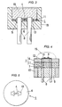
- FIGURE 3 is a cross sectional view of an embodiment of an exothermic instrument for firing explosive of the present invention.
- FIGURE 4 is a cross sectional view of another embodiment of an exothermic instrument for firing explosive of the present invention.
- FIGURE 5 is a plane view of the exothermic instrument for firing explosive as shown in FIGURE 4.
- a punching operation forms simultaneously the grid-like grooves 17 that isolate horizontally and vertically the surface of an alumina green sheet, the raw material of the ceramic substrate 11, into grids, and the round holes 14 centered on the grooves 17. Baking of this green sheet will give the ceramic substrate 11.
- a heat resist layer 6 made of glass ceramics is printed a on the ceramic substrate 11 by a screen printing method and then is baked.
- a silver palladium, the raw material of the conductive electrodes 13 is printed, also by a screen process, in the circumferential periphery of the round holes 14 in the ceramic substrate 11.
- the silver palladium is absorbed from the reverse side of the ceramic substrate 11 into the inner wall of the round holes 14 to form the through hole conductive electrodes 13.
- the conductive electrode 13 has a convex portion 15 to which will be attached a resistance value measuring terminal when trimming the exothermic resistance 4.
- the ceramic substrate 11 with the silver palladium printed will then be baked.
- the exothermic resistance 4 made of ruthenium oxide (RuO 2 ).
- the substrate 11 will be baked again with the mark 16.
- the exothermic resistance 4 will be trimmed, by laser beam, into predetermined resistance value.
- circuit board 1 for the explosive firing exothermic instrument as seen FIGURE 2, a punching operation forms simultaneously the grid-like grooves 17 and round holes 5 on an alumina green sheet, the raw materials of the ceramic substrate 11, to divide the sheet into a hundred 5 mm x 5 mm square grids. This green sheet is baked into the ceramic substrate 11.
- Printed, by the screen process, and baked on the ceramic substrate 11 will be a heat resist layer 6 made of boron-silicate glass.
- a silver palladium, the raw material of the conductive electrodes 13 is printed, also by screen process, in the circumferential periphery of the round holes 5 in the ceramic substrate 11.
- the silver palladium is absorbed from the reverse side of the ceramic substrate 11 into the inner wall of the round holes 5 to form the through hole conductive electrodes 13.
- Printed at the same time on the grooves 17 will be triangular metal marks 9, which will serve as tick marks when dividing the ceramic substrate 11. The ceramic substrate 11 thus printed will then be baked.
- the exothermic resistance 4 made of ruthenium oxide (RuO 2 ).
- the substrate 11 will be baked again. Then, manual splitting and isolation of the ceramic substrate 11 along the grid-like grooves 17 will allow to have the circuit board 1 for explosive firing exothermic instrument.
- the ceramic substrate 11 may have the round holes 5 opened and grooves 17 formed, both by laser beam.
- FIGURE 3 shows an exemplary exothermic instrument for explosive firing that uses the circuit board 1 thus manufactured.
- the exothermic instrument is housed in the insulating container 18.
- a pair of electrode pins 8 pass through the bottom of the insulating container 18 to be inserted into the round hole of the circuit board 1 for explosive igniting exothermic instrument.
- the explosive 19 is loaded into the insulating container 18.
- the explosive igniting exothermic instrument acts as follows.
- the electrode pins 8 are connected to a power supply to flow an electric current
- the exothermic resistance 4 of the circuit board 1 for explosive igniting exothermic instrument gets heated to ignite and combust the explosive 19.
- the heat emanating from the exothermic resistance 4 is kept from dissipating over the ceramic substrate 11 due to the existence of the heat resist layer 6, and is therefore transferred efficiently to the explosive 19, which will thus be ignited assuredly.
- FIGURES 4 and 5 are the cross sectional and plan views, respectively, of another exemplary exothermic instrument for explosive firing to which this invention applies.
- two electrode pins 8 in the exothermic instrument pass through the insulator 9 packed into the metal cylinder 10.
- the base substrate 11 made of ceramics and the heat resist layer 6 made of glass or glass ceramics.
- the tip of the electrode pin 8 is connected with the though hole silver-based electric conductor 7 loaded into the holes opened in the base substrate 11, while the conductor 7 is connected to the through hole silver-based electric conductor 12 loaded into the holes opened in the heat resist layer 6.
- the tip of the conductor 12 is connected with the terminal electrode 13 fixed on the heat resist layer 6, while the terminal electrode 13 is bridged by the exothermic resistance 4 with its neck-formed central part.
- the explosive 19 is applied on the exothermic resistance 4 in such a fashion that the former envelopes the latter.
- the electrode pins 8 are connected to a power supply (not shown).
- the exothermic instrument for firing an explosive comprises a circuit board 1 having a heat resist layer 6 on a substrate 11 and an exothermic resistance 4, which connects to a pair of through hole conductive electrodes 13 passing through the substrate 11, contacting with the explosive 19 on the heat resist layer 6, a pair of electrode pins 8, each one thereof is inserted into each one of the through hole conductive electrodes, and an insulator for holding the circuit board 1 through which the electrode pins 8 pass.
Landscapes
- Engineering & Computer Science (AREA)
- General Engineering & Computer Science (AREA)
- Computer Hardware Design (AREA)
- Microelectronics & Electronic Packaging (AREA)
- Manufacturing & Machinery (AREA)
- Surface Heating Bodies (AREA)
- Manufacturing Of Printed Wiring (AREA)
- Parts Printed On Printed Circuit Boards (AREA)
Claims (7)
- Schaltungsplatine zur Installation in ein exothermes Instrument, mit:dadurch gekennzeichnet, dasseinem Substrat (11), das aus einem keramischen Material gefertigt ist,einem Paar von Durchgangslöchern (5, 14), die durch das Substrat hindurchgehen,einer wärmeresistenten Schicht (6), die an zumindest einem Teil des Substrats (11) zur Verfügung gestellt ist, undeinem exothermen Widerstand (4) an der wärmeresistenten Schicht (6),
die innere Wand und eine Umfangsperipherie jedes der Durchgangslöcher mit einem leitenden Material zur Bildung von jeweils einer leitenden Elektrode (13) bedeckt ist,
der exotherme Widerstand angeordnet ist, um mit dem Paar von leitenden Elektroden zu verbinden, und
die wärmeresistente Schicht (6) aus einem Glas oder einem glaskeramischen Material gefertigt ist und ein Borsilikat-Blei-Glas enthält. - Schaltungsplatine nach Anspruch 1, wobei die wärmeresistente Schicht (6) eine Mischung enthält, die ein Aluminiumoxid-Keramik-Pulver und ein Borsilikat-Blei-Glas umfasst.
- Exothermes Instrument zur Zündung eines Explosivstoffes (19), mit:einer Schaltungsplatine (1) nach Anspruch 1 oder 2, die mit dem Explosivstoff (19) auf der wärmeresistente Schicht (6) in Kontakt steht,einem Paar von Elektrodenanschlussstiften (8), wobei jeder davon jeweils in eines der Durchgangslöcher der Schaltungsplatine (1) eingesetzt ist, undeinem Isolator (9, 18) zum Stützen der Schaltungsplatine (1), durch die die Elektrodenanschlussstifte (8) hindurchgehen.
- Exothermes Instrument nach Anspruch 3, wobei die Schaltungsplatine (1) und der Isolator (9, 18) in einem zylindrischen Gehäuse (10) untergebracht sind, das mit dem Explosivstoff (19) gefüllt ist.
- Herstellungsverfahren einer Schaltungsplatine (1) nach Anspruch 1 oder 2 zur Installation in ein exothermes Instrument, mit:einem Schritt zur Fertigung des Substrats (11) so groß wie eine Vielzahl der gegenständlichen Schaltungsplatinen (1), die das Paar von Durchgangslöchern (5, 14) aufweisen, die durch jedes der gegenständlichen Schaltungsplatinen (1) hindurchgehen,einem Schritt zur Bildung der wärmeresistenten Schicht (6) an einem mittleren Bereich von jedem der Paare von Durchgangslöchern (5, 14) mit einem Abstand der gegenständlichen Schaltungsplatine (1) auf dem Substrat (11),einem Schritt zur Bildung des Paars von leitenden Elektroden (13) an den inneren Wänden und den Umfangsperipherien von jedem der Paare der Löcher (5, 14),einem Schritt zur Bildung des exothermen Widerstands (4) an jeder der wärmeresistenten Schichten (6), undeinem Schritt zur Trennung der vielen Schaltungsplatinen (1) in jede einzelne davon.
- Herstellungsverfahren nach Anspruch 5, wobei in dem keramischen Material des Substrats (11) gitterähnliche Rillen (17) gebildet werden, um die vielen Schaltungsplatinen entlang der Rillen (17) zu trennen.
- Herstellungsverfahren nach Anspruch 5, wobei jedes Loch der Paare von Löchern (5, 14) in einer Rille (17) angeordnet ist, um die vielen Schaltungsplatinen (1) zu trennen.
Applications Claiming Priority (3)
| Application Number | Priority Date | Filing Date | Title |
|---|---|---|---|
| JP9055719A JPH10253059A (ja) | 1997-03-11 | 1997-03-11 | 火薬点火発熱具用回路板の製造方法 |
| JP55719/97 | 1997-03-11 | ||
| JP5571997 | 1997-03-11 |
Publications (3)
| Publication Number | Publication Date |
|---|---|
| EP0864844A2 EP0864844A2 (de) | 1998-09-16 |
| EP0864844A3 EP0864844A3 (de) | 1999-08-04 |
| EP0864844B1 true EP0864844B1 (de) | 2003-06-04 |
Family
ID=13006689
Family Applications (1)
| Application Number | Title | Priority Date | Filing Date |
|---|---|---|---|
| EP98104279A Expired - Lifetime EP0864844B1 (de) | 1997-03-11 | 1998-03-10 | Brückenzünder für Explosivstoffe und Verfahren zum Herstellen eines solchen Zünders |
Country Status (4)
| Country | Link |
|---|---|
| US (1) | US6129976A (de) |
| EP (1) | EP0864844B1 (de) |
| JP (1) | JPH10253059A (de) |
| DE (1) | DE69815184T2 (de) |
Families Citing this family (10)
| Publication number | Priority date | Publication date | Assignee | Title |
|---|---|---|---|---|
| US6321690B1 (en) | 1997-01-17 | 2001-11-27 | North American Industrial Services, Inc. | Device, system and method for on-line explosive deslagging |
| US6755156B1 (en) | 1999-09-13 | 2004-06-29 | Northamerican Industrial Services, Inc. | Device, system and method for on-line explosive deslagging |
| US6431073B1 (en) | 1998-01-14 | 2002-08-13 | North American Industrial Services, Inc. | Device, system and method for on-line explosive deslagging |
| US6363853B1 (en) * | 1999-09-17 | 2002-04-02 | Apti, Inc. | Electrically initiated distributed igniter |
| US6584905B1 (en) * | 2000-11-06 | 2003-07-01 | Richard N. Snyder | Plated through-hole ignitor for detonation cord or shock tube |
| DE102007022071A1 (de) * | 2007-05-08 | 2008-11-13 | Sdi Molan Gmbh & Co. Kg | Zünder für pyrotechnische Wirkmassen |
| JP5450964B2 (ja) * | 2008-02-29 | 2014-03-26 | 三星ダイヤモンド工業株式会社 | スクライブ装置及びスクライブ方法 |
| US7845277B2 (en) * | 2008-05-28 | 2010-12-07 | Autoliv Asp, Inc. | Header assembly |
| RU2473040C1 (ru) * | 2011-08-12 | 2013-01-20 | Российская Федерация, от имени которой выступает государственный заказчик - Государственная корпорация по атомной энергии "Росатом" | Способ изготовления электромеханических инициаторов |
| CN110740569A (zh) * | 2018-07-19 | 2020-01-31 | 鸿富锦精密工业(武汉)有限公司 | 印刷电路板 |
Family Cites Families (18)
| Publication number | Priority date | Publication date | Assignee | Title |
|---|---|---|---|---|
| US2882820A (en) * | 1954-08-11 | 1959-04-21 | American Cyanamid Co | Electric blasting initiator |
| BE540685A (de) * | 1954-08-23 | |||
| JPS5537238Y2 (de) * | 1978-06-30 | 1980-09-01 | ||
| CH643056A5 (de) * | 1978-08-10 | 1984-05-15 | Inventa Ag | Elektrische zuendvorrichtung. |
| DE2945803A1 (de) * | 1979-11-13 | 1981-05-27 | Heko - Elektronik GmbH & Co KG, 2804 Lilienthal | Einrichtung zum zuenden eines spreng-oder treibstoffes |
| ZA852777B (en) * | 1984-05-24 | 1985-11-27 | Inventa Ag | Pole body for an electric fuze,method of manufacturing and method of using the pole body |
| DE3621667A1 (de) * | 1985-06-29 | 1987-01-08 | Toshiba Kawasaki Kk | Mit einer mehrzahl von dickfilmen beschichtetes substrat, verfahren zu seiner herstellung und dieses enthaltende vorrichtung |
| JPS62265796A (ja) * | 1986-05-14 | 1987-11-18 | 株式会社住友金属セラミックス | セラミツク多層配線基板およびその製造法 |
| US4729315A (en) * | 1986-12-17 | 1988-03-08 | Quantic Industries, Inc. | Thin film bridge initiator and method therefor |
| US4944225A (en) * | 1988-03-31 | 1990-07-31 | Halliburton Logging Services Inc. | Method and apparatus for firing exploding foil initiators over long firing lines |
| US5256836A (en) * | 1989-06-09 | 1993-10-26 | Toshiba Lighting & Technology Corporation | Thick film hybrid circuit board device and method of manufacturing the same |
| DE3934971C1 (de) * | 1989-10-20 | 1991-01-24 | Schott Glaswerke, 6500 Mainz, De | |
| JPH05133699A (ja) | 1991-11-11 | 1993-05-28 | Nippon Koki Kk | ガス発生装置用電気式点火具 |
| US5243492A (en) * | 1992-08-27 | 1993-09-07 | Coors Ceramics Company | Process for fabricating a hermetic coaxial feedthrough |
| US5912427A (en) * | 1993-02-26 | 1999-06-15 | Quantic Industries, Inc. | Semiconductor bridge explosive device |
| JPH07221104A (ja) * | 1994-01-28 | 1995-08-18 | Fujitsu Ltd | 半導体装置の製造方法及び半導体装置及び電極ピン形成用マスク及び電極ピン形成用マスクを用いた試験方法 |
| US5543586A (en) * | 1994-03-11 | 1996-08-06 | The Panda Project | Apparatus having inner layers supporting surface-mount components |
| US5847309A (en) * | 1995-08-24 | 1998-12-08 | Auburn University | Radio frequency and electrostatic discharge insensitive electro-explosive devices having non-linear resistances |
-
1997
- 1997-03-11 JP JP9055719A patent/JPH10253059A/ja active Pending
-
1998
- 1998-03-10 EP EP98104279A patent/EP0864844B1/de not_active Expired - Lifetime
- 1998-03-10 US US09/038,257 patent/US6129976A/en not_active Expired - Fee Related
- 1998-03-10 DE DE69815184T patent/DE69815184T2/de not_active Expired - Fee Related
Also Published As
| Publication number | Publication date |
|---|---|
| DE69815184D1 (de) | 2003-07-10 |
| EP0864844A2 (de) | 1998-09-16 |
| EP0864844A3 (de) | 1999-08-04 |
| JPH10253059A (ja) | 1998-09-25 |
| DE69815184T2 (de) | 2003-12-18 |
| US6129976A (en) | 2000-10-10 |
Similar Documents
| Publication | Publication Date | Title |
|---|---|---|
| US4422381A (en) | Igniter with static discharge element and ferrite sleeve | |
| US4307663A (en) | Static discharge disc | |
| KR100390109B1 (ko) | 정전기적 방전에 대해 보호되는 포토에칭된 필라멘트파이로테크닉 시동기 | |
| EP1933108B1 (de) | Halbleiterbrücke, zündvorrichtung und gasgenerator | |
| JP3136144B2 (ja) | 電気式火薬用起爆装置および起爆システム | |
| US7247250B2 (en) | Method for manufacturing a fast heat rise resistor | |
| CN101632000B (zh) | 点火元件搭载电容器、顶盖组件及点火装置 | |
| WO2008050861A1 (en) | Squib and gas generator for air bag and gas generator for seat belt pretensioner | |
| US6129976A (en) | Exothermic instrument for firing explosive | |
| US20050115435A1 (en) | Electro-explosive device with laminate bridge | |
| JP3175051B2 (ja) | 電気発火式イニシエータ | |
| WO2008066174A1 (en) | Header assembly, squib, airbag gas generating device, and seatbelt pretentioner gas generating device | |
| JP2003205823A5 (de) | ||
| JP2979533B2 (ja) | 火薬点火用発熱体 | |
| JP3860900B2 (ja) | 点火用発熱具および点火具 | |
| JPH07167594A (ja) | イグナイター用ヘッダーおよびその製造方法 | |
| JPH10170197A (ja) | 鈍感型スクイブ | |
| JP2003083699A (ja) | 電気発火式イニシエータ |
Legal Events
| Date | Code | Title | Description |
|---|---|---|---|
| PUAI | Public reference made under article 153(3) epc to a published international application that has entered the european phase |
Free format text: ORIGINAL CODE: 0009012 |
|
| AK | Designated contracting states |
Kind code of ref document: A2 Designated state(s): DE FR GB SE |
|
| AX | Request for extension of the european patent |
Free format text: AL;LT;LV;MK;RO;SI |
|
| PUAL | Search report despatched |
Free format text: ORIGINAL CODE: 0009013 |
|
| AK | Designated contracting states |
Kind code of ref document: A3 Designated state(s): AT BE CH DE DK ES FI FR GB GR IE IT LI LU MC NL PT SE |
|
| AX | Request for extension of the european patent |
Free format text: AL;LT;LV;MK;RO;SI |
|
| 17P | Request for examination filed |
Effective date: 20000202 |
|
| AKX | Designation fees paid |
Free format text: DE FR GB SE |
|
| 17Q | First examination report despatched |
Effective date: 20020225 |
|
| GRAH | Despatch of communication of intention to grant a patent |
Free format text: ORIGINAL CODE: EPIDOS IGRA |
|
| GRAH | Despatch of communication of intention to grant a patent |
Free format text: ORIGINAL CODE: EPIDOS IGRA |
|
| GRAA | (expected) grant |
Free format text: ORIGINAL CODE: 0009210 |
|
| AK | Designated contracting states |
Designated state(s): DE FR GB SE |
|
| REG | Reference to a national code |
Ref country code: GB Ref legal event code: FG4D |
|
| REG | Reference to a national code |
Ref country code: SE Ref legal event code: TRGR |
|
| REF | Corresponds to: |
Ref document number: 69815184 Country of ref document: DE Date of ref document: 20030710 Kind code of ref document: P |
|
| ET | Fr: translation filed | ||
| PLBE | No opposition filed within time limit |
Free format text: ORIGINAL CODE: 0009261 |
|
| STAA | Information on the status of an ep patent application or granted ep patent |
Free format text: STATUS: NO OPPOSITION FILED WITHIN TIME LIMIT |
|
| 26N | No opposition filed |
Effective date: 20040305 |
|
| PGFP | Annual fee paid to national office [announced via postgrant information from national office to epo] |
Ref country code: DE Payment date: 20060302 Year of fee payment: 9 |
|
| PGFP | Annual fee paid to national office [announced via postgrant information from national office to epo] |
Ref country code: FR Payment date: 20060308 Year of fee payment: 9 |
|
| PG25 | Lapsed in a contracting state [announced via postgrant information from national office to epo] |
Ref country code: SE Free format text: LAPSE BECAUSE OF NON-PAYMENT OF DUE FEES Effective date: 20070311 |
|
| EUG | Se: european patent has lapsed | ||
| GBPC | Gb: european patent ceased through non-payment of renewal fee |
Effective date: 20070310 |
|
| REG | Reference to a national code |
Ref country code: FR Ref legal event code: ST Effective date: 20071130 |
|
| PG25 | Lapsed in a contracting state [announced via postgrant information from national office to epo] |
Ref country code: DE Free format text: LAPSE BECAUSE OF NON-PAYMENT OF DUE FEES Effective date: 20071002 |
|
| PGFP | Annual fee paid to national office [announced via postgrant information from national office to epo] |
Ref country code: SE Payment date: 20060306 Year of fee payment: 9 |
|
| PG25 | Lapsed in a contracting state [announced via postgrant information from national office to epo] |
Ref country code: GB Free format text: LAPSE BECAUSE OF NON-PAYMENT OF DUE FEES Effective date: 20070310 |
|
| PG25 | Lapsed in a contracting state [announced via postgrant information from national office to epo] |
Ref country code: FR Free format text: LAPSE BECAUSE OF NON-PAYMENT OF DUE FEES Effective date: 20070402 |
|
| PGFP | Annual fee paid to national office [announced via postgrant information from national office to epo] |
Ref country code: GB Payment date: 20060308 Year of fee payment: 9 |