EP0865013A2 - Méthode et système de détection d'incendie - Google Patents
Méthode et système de détection d'incendie Download PDFInfo
- Publication number
- EP0865013A2 EP0865013A2 EP98301886A EP98301886A EP0865013A2 EP 0865013 A2 EP0865013 A2 EP 0865013A2 EP 98301886 A EP98301886 A EP 98301886A EP 98301886 A EP98301886 A EP 98301886A EP 0865013 A2 EP0865013 A2 EP 0865013A2
- Authority
- EP
- European Patent Office
- Prior art keywords
- fire
- gas
- recognising
- sensor
- fire detection
- Prior art date
- Legal status (The legal status is an assumption and is not a legal conclusion. Google has not performed a legal analysis and makes no representation as to the accuracy of the status listed.)
- Granted
Links
Images




Classifications
-
- G—PHYSICS
- G08—SIGNALLING
- G08B—SIGNALLING SYSTEMS, e.g. PERSONAL CALLING SYSTEMS; ORDER TELEGRAPHS; ALARM SYSTEMS
- G08B17/00—Fire alarms; Alarms responsive to explosion
- G08B17/10—Actuation by presence of smoke or gases, e.g. automatic alarm devices for analysing flowing fluid materials by the use of optical means
-
- G—PHYSICS
- G08—SIGNALLING
- G08B—SIGNALLING SYSTEMS, e.g. PERSONAL CALLING SYSTEMS; ORDER TELEGRAPHS; ALARM SYSTEMS
- G08B17/00—Fire alarms; Alarms responsive to explosion
- G08B17/10—Actuation by presence of smoke or gases, e.g. automatic alarm devices for analysing flowing fluid materials by the use of optical means
- G08B17/11—Actuation by presence of smoke or gases, e.g. automatic alarm devices for analysing flowing fluid materials by the use of optical means using an ionisation chamber for detecting smoke or gas
- G08B17/113—Constructional details
Definitions
- the present invention relates to a fire detection method and a fire detection apparatus and to a recording medium recorded with a fire detection program and a fire detection data, particularly to a technology for detecting at an initial stage of a fire which increases in humidity by heating among fires generated by heating some objects such as heat evolution of an apparatus due to overload or heat generation in electric wiring.
- a fire detector In a prior art fire detection method, smoke, heat, burning gas, or organic gas generated by a fire has been sensed.
- a fire detector there is a smoke detector, a heat detector, a carbonic acid gas detector, a chlorine gas detector, or the like.
- the above prior art fire detectors have the following problems which have yet to be solved. Specifically, since the smoke detector, heat detector, and the like sense smoke or heat which is necessarily generated during a fire, they are positive to find a fire, however, are low in sensitivity to find a fire in the stage of smoldering or baking before generating flame or smoke or smokeless burning. Further, the chlorine gas detector is high in sensitivity, however, all combustibles don't generate chlorine gas, and it cannot be a general-purpose fire detector.
- an object of the present invention is to provide a novel fire detection method which detects a fire with a high sensitivity in the stage of initial baking or smokeless burning.
- Another object of the present invention is to provide a highly sensitive, inexpensive fire detection apparatus which can be achieved with an inexpensive quartz crystal microbalance.
- a further object of the present invention is to provide a recording medium recorded with a program for the above fire detection and with a fire detection data.
- a fire detection method comprises the steps of:
- the senor may have a burning gas detection function, and may further comprise a step for recognizing a fire when generation of a burning gas and the humidity increase are detected almost simultaneously.
- a fire detection method comprising the steps of:
- the step for detecting humidity changes in a plurality of places may comprise the steps of:
- the fire detection method may further comprise a step for detecting generation of burning gas due to a fire by matching data of processing result obtained in the processing step with the database continuously, when the detected gas is recognized as a water vapor by the recognizing step.
- the recognizing step may make recognition of the gas type using a pattern recognition method of principal component analysis.
- the fire detection method may further comprise a step which when a humidity increase is detected by the recognizing step and it is highly possible to be a fire, in a gas classification map of principal component analysis as the database, a distance D t between a response Y of the sensor apparatus and the center of cluster of burning gas is calculated, the distance D t and an immediately previous distance D t-1 are compared, if D t ⁇ D t-1 , a flag S is increment by 1, if D t > D t-1 , the flag S is reset to 0, this procedure is repeated several times, and when S exceeds a reference number of times M, response Y of the sensor apparatus is recognized to approach the cluster of burning gas to recognize a fire.
- a fire detection apparatus comprises:
- the sensors may also have a burning gas detection function, and the recognizing means may recognize a fire when detecting generation of the burning gas and the humidity increase are detected almost simultaneously.
- a fire detection apparatus comprises:
- the detection means may cbmprise:
- the recognizing means may detect generation of burning gas due to a fire by matching data of processing result obtained by the second processing means with the database continuously, when the detected gas is recognized as a water vapor by the third processing means.
- the third processing means may make recognition of the gas type using a pattern recognition method of principal component analysis.
- the recognizing means which when a humidity increase is detected by the third processing means and it is recognized as highly possible to be a fire, in a gas classification map of principal component analysis as the database, a distance D t between a response Y of the sensor apparatus and the center of cluster of burning gas is calculated, the distance D t and an immediately previous distance D t-1 are compared, if D t ⁇ D t-1 , a flag S is increment by 1, if D t > D t-1 , the flag S is reset to 0, this procedure is repeated several times, and when S exceeds a reference number of times M, response Y of the sensor apparatus is recognized to approach the cluster of burning gas to recognize a fire.
- the detection means may comprise, by sputtering a sintered polymer formed by hot-pressing granules of hydrocarbon polymers with particle diameters ranging from 50 to 200 micrometers, a chemical sensor probe having a hydrocarbon-based polymer thin film on a piezoelectric mass transducer, the hydrocarbon-based polymer thin film containing carbon, hydrogen, and oxygen, and content of the oxygen is within a range from 2 to 20%.
- the polymer thin film may be formed by, when sputtering a sputtering target in a radio-frequency discharge, using a sintered polymer formed by hot-pressing granules of hydrocarbon polymers having particle diameters ranging from 50 to 200 micrometers as the sputtering target.
- the detection means may comprise, on the surface of a piezoelectric mass transducer, a chemical sensor probe having an organic thin film by spattering with an organic material as a target and with an induction coupled plasma ion source.
- the organic thin film may be formed by a sputtering with an organic material as a target and with an induction coupled plasma ion source.
- a recording medium recorded with a fire detection program for making fire detection by a computer may cause the computer:
- the fire detection program may cause the computer, when detecting humidity changes in the plurality of places:
- the fire detection program may cause the computer to detect generation of burning gas due to a fire by matching data of processing result with the database continuously, when the computer is caused to recognize the detected gas as water vapor.
- the fire detection program may cause the computer to make recognition of the gas type using a pattern recognition method of principal component analysis.
- the fire detection program may cause the computer, in a gas classification map of principal component analysis as the database, to calculate a distance D t between a response Y of the sensor apparatus and the center of cluster of burning gas, compare the distance D t with an immediately previous distance D t-1 , if D t ⁇ D t-1 , increment a flag S by 1, if D t > D t-1 , reset the flag S to 0, repeat this procedure several times, and when S exceeds a reference number of times M, and recognize response Y of the sensor apparatus approaching the cluster of burning gas to recognize a fire.
- a recording medium recorded with data for detecting a fire by a computer the data may be obtained by processing resonance frequency changes of each of a plurality of quartz crystal microbalances, which different films are formed on the surfaces respectively, according to mass changes of the detected burning gases or water vapor on the films.
- the present invention can provide a relatively inexpensive fire detection apparatus by using an inexpensive quartz crystal microbalance. Still further, the present invention can positively sense a fire since it recognizes a fire from humidity changes at a plurality of positions. Yet further, with the present invention, more positive fire detection is possible since it senses generation of a burning gas using sensor response varying with time.
- the present invention has been accomplished through intensive studies of the inventors on adsorption of a detected gas to a film particularly in the initial stage of a fire.
- fluorine-containing polymers and hydrocarbons such as polyethylene, polychlorotrifluoroethylene, or a mixture of polyethylene and polytetrafluoroethylene, or amino acids such as phenylalanine, or sugars such as glucose as a target
- a film is formed on a quartz crystal microbalance by radio-frequency sputtering, and changes in resonance frequency due to adsorption to these films of burning gas of a PVC (polyvinylchloride) cable and burning gas of a circuit board have been investigated.
- PVC polyvinylchloride
- quartz crystal microbalance formed with a film can be regarded as a sensor for detecting a gas.
- these gas sensors are sensitive to gases not contained in normal atmosphere, such as hydrogen chloride contained in burning gas, they are also sensitive to a water vapor. Therefore, by a single sensor, it is impossible to distinguish whether a burning gas is detected or a water vapor is detected.
- the sensor apparatus comprises a set of L units (L being an integer of 2 or more) of quartz crystal microbalances coated with different films, that is, sensors differing in gas adsorption characteristics.
- the L-dimensional data Y is hereinafter referred to as response Y of the sensor apparatus.
- Distribution of response Y of the sensor apparatus as the multidimensional (L-dimensional) data is converted to distribution of low-dimensional data without missing information as possible by principal component analysis (See Okuno, Kume, Haga, and Yoshizawa, "Multivariate Method", NIKKA GIREN, 1971) which is one of pattern recognition methods, and the result is plotted on a gas classification map.
- principal component analysis See Okuno, Kume, Haga, and Yoshizawa, "Multivariate Method", NIKKA GIREN, 1971
- Z ⁇ 1 ⁇ (w 1 /X) + ⁇ 2 ⁇ (w 2 /X) + ... + ⁇ L ⁇ (w L /X).
- One which satisfies formula (1) and non-correlated with the first component and whose dispersion is the maximum is defined as a second principal component.
- response Y of the sensor apparatus when response Y of the sensor apparatus is plotted on a gas classification map, response Y of the sensor apparatus is plotted in cluster form at a specific position on the gas classification map according to the type of the gas and a water vapor.
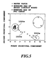
- Fig. 5 is an example of the gas classification map, while detail thereof will be described in a practical example later, a water vapor, burning gas of PVC cable and burning gas of epoxy circuit board are respectively plotted at specific positions. That is, the gas classification map are a database for recognizing gas types.
- the cluster data on the gas classification map can be stored in a recording medium such as a floppy disk or a CD-ROM.
- Response Y of the sensor apparatus to unknown gases including a water vapor can be plotted on the gas classification map to recognize gas types from which plot is close to which cluster.
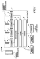
- Fig. 1 shows the structure of an embodiment of fire detection apparatus according to the present invention.
- a sensor for detecting a fire it uses a reference quartz crystal microbalance 1 and a plurality of L units of gas detection quartz crystal microbalances 3 provided with a film 2 on the surface. Resonance frequencies of these quartz crystal microbalances 1 and 3 are 9 MHz as an example.
- the gas detection quartz crystal microbalances 3 can be mounted up to 8 units, and the respective films 2 are different in materials and fabrication conditions to change the adsorption characteristics from each other.
- gas detection quartz crystal microbalances 3 and the reference quartz crystal microbalance 1 are provided with oscillator circuits 4 and 5, respectively, so that the oscillator circuits 4 and 5 oscillate at resonance frequencies of corresponding gas detection quartz crystal microbalances 3 and the reference quartz crystal microbalance 1.
- a multiplexer 6 selects one of the oscillator circuits 4.
- a mixer 7 outputs a signal having a frequency of a frequency difference between outputs of the selected oscillator circuit 4 and the oscillator circuit 5.
- a counter 8 measures frequency of this output signal of the mixer 7.
- a plurality of sensor apparatuses 9 comprising the above elements from 1 to 8 can be connected to a computer 10 using an interface such as RS485 (not shown) which is possible to make long distance communications and monitor humidities in a plurality of areas, followed by data processing.
- a computer 10 a general personal computer or the like can be applied.
- the multiplexer 6 selects any one of the oscillator circuits 4 in a certain period, for example, at every one second, the mixer 7 outputs a signal having a frequency difference between outputs of the selected oscillator circuit 4 and the reference oscillator circuit 5. Since the resonance frequency of the reference quartz crystal microbalance 1 connected to the oscillator circuit 5 is always constant, the mixer 7 outputs a signal having a frequency proportional to the mass of a gas adsorbed to the film 2 on the gas detection quartz crystal microbalance 3.
- the counter 8 Since the counter 8 measures frequency of this output signal, it finally outputs the mass of the gas (specifically, number of counts corresponding to the mass of the gas) adsorbed to the film 2 on the gas detection quartz crystal microbalance 3. By selecting the oscillator circuits 4 periodically by the multiplexer 6, the mass of the gas adsorbed to the film 2 on the respective gas detection quartz crystal microbalances 3 can be outputted.
- These sensor apparatuses 9 are disposed in N areas (N being an integer of 2 or more), and outputs of the respective sensor apparatuses 9 are monitored by the computer 10.
- a distance D t between response Y of the sensor apparatus 9 and the center of gravity of cluster of burning gas are calculated in a gas classification map such as principal component analysis.
- D t and immediately previous distance D t-1 are compared, and if D t ⁇ D t-1 , flag S is incremented by 1. If D t > D t-1 , flag S is reset to 0. This procedure is repeated several times, when S exceeds a reference number of times, response Y of the sensor apparatus 9 is recognized to approach the cluster of burning gas, thereby making more positive fire recognition.
- Recognition criteria of J can be varied depending on the area of the place to be fire detected, or how many false reports due to malfunction of the sensor apparatus are decreased. That is, when the sensor apparatus malfunctions, the flag of the area may be always 0, under which condition normal humidity increase is recognized to be a fire with the recognition criteria of 0 ⁇ J ⁇ N. In such a case, false reports can be reduced by changing the recognition criteria of S11, for example, to 0 ⁇ J ⁇ N-1.
- flag f i may always be 1. In such a case, false reports can be reduced by changing the recognition criteria of S11 to 1 ⁇ J ⁇ N-1. The fire detection sensitivity is, however, decreased.
- recognition criteria of J is determined from even balance of loss due to false report and loss due to a fire.
- a humidity increase occurs in the initial stage of a fire.
- burning gases are generated such as hydrogen chloride gas from a PVC cable.
- the burning gas can be detected to make fire recognition more positive.
- a humidity increase it is possible to recognize that it is a normal humidity increase or a humidity increase due to a fire, by investigating how the response Y of the sensor apparatus 9 varies with time.
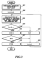
- the move positive five recognition methods will be described below with reference to the flow chart shown in Fig. 3.
- a distance between the response Y of the sensor apparatus 9 and the center of gravity of cluster of a known burning gas or a water vapor on a gas classification map of database previously stored in an internal memory of the computer 10, does not always provide right judgements. If the response Y of the sensor apparatus 9 approaches the cluster of burning gas and it is still closer to the cluster of a water vapor, it is recognized as a water vapor. When it approaches the cluster of burning gas, even if it is close to the cluster of a water vapor, burning gas should be detected.
- the computer 10 detects a humidity increase in a gas classification map such as principal component analysis by executing the steps of S1 to S11 of Fig. 2.
- a gas classification map such as principal component analysis
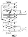
- distance D t between the response Y of the sensor apparatus 9 and the center of the cluster of burning gas is calculated (where t is number of recognition times) (S23).
- D t and immediately previous distance D t-1 are compared, if D t ⁇ D t-1 (S24), flag S is incremented by 1 (S25). If D t > D t-1 , S is reset to 0 (S26). That is, it is recognized as to whether response Y of the sensor apparatus 9 continuously approaches the cluster of burning gas. This procedure is repeated several times. When S exceeds a reference number of times (S27), it is recognized that response Y of the sensor apparatus 9 approaches the cluster of burning gas, and a fire is recognized to generate a fire alarm (S29).
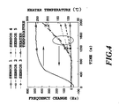
- Fig. 4 shows how frequency change of each quartz crystal microbalance of sensor A varies with time.
- the axis of ordinates indicates a frequency change of the quartz crystal microbalance, which can be regarded as a mass change of gas.
- the time interval of data acquisition is 5 seconds. Temperature change of a heater is also shown.
- Five quartz crystal microbalances are used as sensor 1 to sensor 5.
- Film materials of the respective quartz crystal microbalances are: sensor 1: polychlorotrifluoroethylene, sensor 2: phenylalanine, sensor 3: polychlorotrifluoroethylene and phenylalanine, sensor 4: pyrolytic graphite, and sensor 5: glucose.
- the fire detection apparatus of the present invention is possible to provide more sensitive fire detection than prior art fire detectors, if it is a fire providing a humidity increase at an early stage.
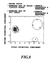
- Fig. 5 shows response to a water vapor, response to gases generated by heating a PVC cable, and response to gases generated by heating an epoxy circuit board, plotted on a gas classification map by principal component analysis. Concentrations of the water vapor are those at relative humidities of 3 % to 70 %.
- the PVC cable and the epoxy circuit board were heated at 200 °C to 260 °C in a test room, and responses to the generated gases were measured.
- Response Y of the sensor apparatus can be plotted on the gas classification map of Fig. 5, and gas be recognized from plot thereof is close to which cluster.
- Time interval of making the gas recognition is 100 seconds. After beginning measurement in Fig. 4, responses Y of the sensor apparatus from 1000 seconds to 2000 seconds are plotted by mark X at every 100 seconds in Fig. 5. Responses Y of the sensor apparatus after 1000 seconds are plotted at the cluster of a water vapor, responses Y of the sensor apparatus after 2000 seconds are plotted at the cluster of burning gas of PVC cable.
- a water vapor is generated from the PVC cable at an initial stage of heating and, as the heating temperature increases, burning gas specific to the PVC cable is generated.
- threshold value of gas detection is set to 20 Hz in an average value of resonance frequency change of the quartz crystal microbalance. Threshold value of gas detection determines the sensitivity of fire detection.
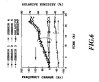
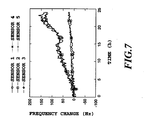
- Fig. 8 shows data exceeding 20 Hz in average value of resonance frequency change of the quartz crystal microbalance sensor, selecting 10 points at the same time for the sensor apparatuses A and B, determined for response Y of the sensor apparatuses for A and B, and plotted on a gas classification map using principal component analysis.
- timing of exceeding an average value 20 Hz was the same.
- X mark is a response of the sensor apparatus A determined from Fig. 6, and ⁇ mark is a response of the sensor apparatus B determined from Fig. 7. Both responses are plotted in water vapor clusters, and thus recognized as a water vapor.
- distance D t between the response of the sensor apparatus and the center of the cluster of PVC cable burning gas and the cluster of epoxy circuit board burning gas was calculated one by one.
- the center of the cluster of epoxy circuit board is the center of gravity (9.5, 4.6) of three points of data of epoxy circuit board burning gas.
- Responses of both the sensor apparatuses did not approach to the cluster of the PVC cable burning gas or the cluster of the epoxy circuit board burning gas.
- a third embodiment of the present invention is a formation method of a polymer thin film used in the above-described detection sensor, and a fourth embodiment relates to a chemical sensor probe, more specifically to a formation technology of a polymer thin film using a hydrocarbon as a basic structure which is superior in adhesiveness to the substrate and film thickness controllability and to a chemical sensor probe using the polymer thin film.
- the polymer thin film according to the third embodiment of the present invention is characterized in that it is formed by a polymer thin film formation method in which a thin film is formed by radio-frequency sputtering of a sputtering target, and a sintered polymer formed by hot-pressed granules of hydrocarbon polymers having particle diameters ranging from 50 to 200 micrometers is used as a sputtering target.
- the chemical sensor probe according to the fourth embodiment of the present invention is formed by sputtering a sintered polymer formed by hot-pressing granules of hydrocarbon polymers having particle diameters ranging from 50 to 200 micrometers, thereby providing a polymeric granularthin film constituting of carbon, hydrogen, and oxygen atoms, and having an oxygen content within a range from 2 to 20% on a piezoelectric mass transducer.
- a sintered polymer having a particle diameter of 50 to 200 ⁇ m is used as a sputtering target.
- the fourth embodiment of the present invention relates to a chemical sensor probe using an organic thin film formed by the aforementioned organic thin film preparation method.
- the sensor probe is composed of the piezoelectric mass transducer coated with a hydrocarbon-based polymer thin film containing C . H . O, and having an O atom content of 2 to 20 %.
- oxygen content of hydrocarbon-based polymer thin film is 2 to 20 %, the thin film exhibits superior adsorption-desorption characteristics as described following embodiments as embodiments which will be shown below.
- a radio-frequency magnetron sputtering apparatus comprises a vacuum chamber 21 in which the high vacuum condition will be attained, a substrate 23, such as a mass detection transducer for chemical sensor to be film-coated, a substrate holder 22 for holding the substrate 23, a sputtering target 24 a raw material to be sputtered, a radio-frequency electrode 26 for mounting the sputtering target 24, a shutter 25 disposed between the substrate 23 and the sputtering target 24, a radio-frequency power generator 28 for applying a radio-frequency voltage to the radio-frequency electrode 26, an impedance-matching controller 27 for adjusting the radio-frequency power generator 28, an oil diffusion pump 29 for evacuating the vacuum chamber 21, an angle valve 32 for opening and closing between the vacuum chamber 21 and the oil diffusion pump 29, an angle valve 33 for evacuation for the oil diffusion pump 29, an oil rotary pump
- a piezoelectric mass transducer for chemical sensor is used as a substrate 23 on the substrate holder 22.
- a quartz crystal microbalance AT-cut, resonance frequency of 9 MHz
- a silicon wafer or a borosilicate glass plate are used for film analysis.
- a sintered polymer is mounted on the radio-frequency electrode 26.
- the sintered polymer is formed by hot-pressing (sintering) granules of hydrocarbon-based polymers having particle diameters ranging from 50 to 200 ⁇ m.
- the sintered polymer is either a sintered polyethylene or a sintered polyvinylidenefluoride. An average porous spacing of these sintered polymer particles is preferred to be about 20 ⁇ m.
- the oil diffusion pump 29 is operated to start up the evacuation system.
- the angle valve 33 for evacuation of the oil diffusion pump is closed, the angle valve 32 is opened to start evacuation.
- the pressure is decreased to about 10 -1 Torr, the angle valve 32 is closed, and the angle valve 33 for evacuation of the oil diffusion pump and the evacuation system main valve 31 are opened to establish high vacuum condition. Baking of the vacuum chamber 21 using the heater 36 or a liquid nitrogen trap attached to the oil diffusion pump 29 is operated to enhance evacuation efficiency, and evacuation is carried out until the gas pressure of about 7 ⁇ 10 -1 Torr is obtained.
- krypton is introduced at a flow rate of 6 cc/min from the krypton gas cylinder 35 through the mass flow controller 34 to adjust gas pressure in the vacuum chamber 21.
- a radio-frequency voltage is applied to the radio-frequency electrode 26 by the radio-frequency power supply 28 to generate a plasma.
- a capacitance in the matching box 27 is adjusted so that a stable plasma condition is obtained, and film preparation is carried out for the intended time.
- the substrate holder 22 is preferably kept at 10 °C by cooling water 36.
- Deposition rate of thin film is 8 ⁇ /min for sintered polyethylene, and 10 ⁇ /min for a sintered polyvinylidenefluoride.
- FTIR Fourier transform infrared
- IR-5M Nippon Bunkosha FT/IR-5M
- HFS-RBS hydrogen forward scattering Rutherford backscattering spectrometer
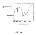
- Fig. 11 shows a FTIR spectrum of polyethylene thin film.
- a signal caused by bending vibration is observed at 1380 and 1450 cm -1 .
- a broad signal caused by O-H stretching vibration is weakly observed at around 3500 cm -1 .
- Resonance frequency of thickness-shear mode of a quartz crystal microbalance (AT-cut, resonance frequency of 9 MHz) is negligible small in temperature coefficient in the vicinity of room temperature, and is thus useful as a piezoelectric mass transducer for chemical sensor. Change in resonance frequency thereof corresponds directly to mass change, and the ratio can be estimated to be 1 ng/Hz [See C. G. Guilbauit and J. M. Jordan, "Analytical Uses of Piezoelectric Crystals: A Review", CRC Critical Reviews in Analytical Chemistry, Vol. 19, No. 1, pp. 1-28 (1988)].
- This quartz crystal microbalance which can be used as a mass detection type chemical probe is coated with polyethylene thin film to a thickness of about 0.5 ⁇ m on both sides of quartz plate.
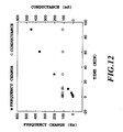
- Fig. 12 shows results of changes in frequency and conductance with time when the chemical sensor probe is exposed to a flow of 100-ppm toluene vapor at 28 °C, using a network analyzer (Hewlett Packard 4195A).
- Hewlett Packard 4195A a network analyzer
- the resonance frequency begins to decrease, and frequency change amount increases with the elapse of time. Because the frequency is measured with an accuracy of 0.1 Hz, gas detection with high sensitivity is possible within short time with low noise.
- the conductance is constant at about 110 mS, it is shown that these frequency changes reflect mass changes, not by softening of the film due to gas-sorption or by phase changes of polymer film.
- results of measuring mass changes induced by gas-sorption for various types of organic vapor are shown in Table 1.
- the concentration of organic vapor is 20 ppm, and the mass change is calculated from frequency shift for three hours.
- the number of absorbed molecules normalized by the film thickness is used as an unit of absorbed gas concentration in the films. Comparing the polar and nonpolar gases, the sorption concentration is higher for the former than for the latter. Among those of organic vapors classified as the same functional group, the greater in molecular weight (the greater in carbon chain), the higher in sorption concentration. It is noteworthy to be mentioned that the organic molecules containing cyclohexane ring is not likely to be sorbed. As shown above, it can be recognized that the present chemical probe has a wide application range.
- Gas-sorption characteristics of the films are closely correlated with the oxygen concentration of the polymer thin film.
- a hydrocarbon polymer thin film having an oxygen ratio of 10% was used, however, the oxygen ratio could be flexibly changed by changing the sputtering condition. It has been found that when the oxygen ratio in the hydrocarbon polymer thin film is in the range from 2 to 20%, the thin film exhibits superior gas-sorption characteristics similar to those shown in the embodiment.
- Table 1 shows the absorption gas-concentration for 20-ppm organic vapors at 28 °C in an AT-cut quartz crystal microbalance (resonance frequency 9 MHz) coated with a polyethylene thin film as described in the present embodiments 3 and 4. Absorbed gas-concentration of 20-ppm organic vapors Organic vapor Absorbed gas-concentration (mmol/l) n-Hexane 53.4 n-Heptane 50.1 n-Octane 70.1 Cyclohexane 2.6 Benzene 47.7 Toluene 90.3 o-Xylene 34.7 m-Xylene 63.3 p-Xylene 85.3 Chlorobenzene 129.1 Acetone 42.8 2-Butanone 90.3 2-Hexanone 121.4 Methyl acetate 32.9 Ethyl acetate 78.4 Cyclohexanol 13.1 Acetaldehyde 38.7 Methylcellosolve 237.2
- Fifth and sixth embodiments of the present invention relate to preparation methods of an organic thin film and a chemical sensor probe. They are especially pertaining to a preparation method of an thickness-controllable organic thin film which has the high adhesiveness to the substrate and has a strong intermolecular interaction, and to a formation method of a chemical sensor probe using the organic thin film.
- the fifth embodiment of the present invention relates to a preparation method of an organic thin film having a strong intermolecular interaction, characterized in that an organic thin film is formed by a sputtering method using an organic material as a target and using an inductively coupled plasma ion source.
- the sixth embodiment of the present invention relates to a preparation method of a chemical sensor probe, characterized by the fact that an organic thin film is coated on the piezoelectric mass transducer by sputtering using an organic material as a target and using an inductively coupled plasma ion source.
- gas-sorption active points can be incorporated in a sputtered polymer thin film with high atomic density by using an inductively coupled plasma capable of generating a high density, and high energy plasma as primary sputtering beam.
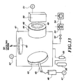
- Fig. 13 shows an example of the schematic diagram of an inductively coupled plasma sputtering apparatus according to the fifth and sixth embodiments.
- the inductively coupled plasma sputtering apparatus comprises a vacuum chamber 41 which is evacuated to the high vacuum-level, a substrate holder 42 mounting a mass detection transducer for chemical sensor and the like, a sputtering target 43 to be a raw material of the film, a target holder 45 holding the sputtering target 43, a capacitively coupled impedance-matching controller 46 used for adjusting the impedance-matching for the sputtering target 43, a 200 KHz target biasing radio-frequency power generator 47 for applying the radio-frequency bias to the sputtering target 43, an inductively coupled plasma ion source 44 for generating an inductively coupled plasma, a quartz window 48 through which radio-frequency is to be biased, an inductively coupled impedance-matching box 50 for the inductively coupled plasma ion source 44, a 13.56 MHz radio-frequency power generator 51 applied to the inductively coupled plasma ion source 44, a copper loop antenna 49 attached to a
- a piezoelectric mass transducer for chemical sensor is mounted on the substrate holder 42. It can typically be a quartz crystal microbalance resonator(AT-cut, resonance frequency of 9 MHz). In some cases, a silicon wafer or a borosilicate glass plate may be used for film analysis. Further, as the sputtering target 43, an organic material as a raw material is set on the target holder 45. A wide-range of polymer material can be used as sputtering target 43 if it is a material having a vapor pressure of less than several Torr at room temperature and at a gas pressure of about 10 -5 Torr.
- PCTFE polychlorotrifluoroethylene
- the oil rotary pump 54 is operated, and the vacuum valve 52 is opened to begin evacuation for vacuum.
- the turbo molecular pump 53 is operated to make high vacuum evacuation. Evacuation is carried out until a gas pressure is reached at the level of 10 -7 Torr.
- helium is introduced from the helium cylinder 56 at a flow rate of 9 cc/min through the mass flow controller 55, and gas pressure in the vacuum chamber 41 is adjusted to about 8 ⁇ 10 -3 Torr by the vacuum valve 52.
- a radio-frequency power of about 200W is applied by 13.56 MHz radio-frequency power generator 51 to generate a plasma in the inductively coupled plasma ion source 44.
- a radio-frequency power of about 50W is applied to the target holder 45 by the 200 KHz target-biasing radio-frequency power generator 47.
- Variable condensers installed in the matching controller (for ion source) 50 and the matching box (for target bias) 46 are adjusted so that a stable plasma condition is obtained, and film formation is carried out for a certain time.
- the substrate holder 42 is preferably water-cooled by circulating cooled water 58.
- the resulting fluoropolymer thin film was analyzed for structure characterization by means of Fourier transform infrared (FTIR) spectrophotometer (Nippon Bunkosha FT/IR-5M) equipped with a mercury-cadmium-tellurium (MCT) detector and X-ray photoelectron spectrometer (XPS, VG Co. ESCALAB. MK-2) using Mg-K ⁇ radiation as an excitation source.
- FTIR Fourier transform infrared
- MCT mercury-cadmium-tellurium
- XPS X-ray photoelectron spectrometer
- the analytical results are shown for the conventionally sputtered PCTFE film obtained by a diode-type capacitively coupled radio-frequency sputtering apparatus which has been widely used as a sputtering coater.
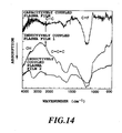
- the sputtered PCTFE films produced by the inductively coupled plasma, as described in the present embodiments 5 and 6, show the different spectra between one which is held on the substrate holder and one which is placed on the peripheral end of the inductively coupled plasma ion source. These are shown as an inductively coupled plasma film 1 and an inductively coupled plasma film 2, respectively.
- Fig. 14 shows the FTIR spectra of the sputtered PCTFE film.
- the capacitively coupled plasma film exhibits the strong signal arisen from the stretching vibration of C-F bond at around 1180 cm -1 .
- the bond dissociation by high-density plasma is promoted, resulting the large number of unsaturated carbons in the film-constituting carbon networks.
- the O-H bonds, which are not observed in the raw material, are considered to be produced by radical reactions with an oxygen source such as water or oxygen remaining in the vacuum chamber.
- Fig. 15 shows the XPS spectra of C 1S region.
- these XPS spectra there is no noticeable difference between the inductively coupled plasma film 1 and the inductively coupled plasma film 2.
- capacitively coupled plasma film there is a main peak in CF 2 region, which indicates that the PCTFE skeleton is not considerably destroyed.
- the signal strength of CF 2 region is reduced, and the signals of the defluorinated moieties, such as CF, C(CFx) or CCl, become to be main peaks.
- oxygen is detected in the inductively coupled plasma film, which has not been detected in the prior art capacitively coupled plasma film, and the film constituting element ratio is: carbon: 41 %, fluorine: 32 %, chlorine: 19 %, and oxygen: 7 %.
- the progressing the defluorination reactions leads to increases the number of radical sites or multiple bond, and the structural changes such as strengthening the carbon networks by crosslinking bonds induced by radical-coupling reaction.
- the oxygen atoms which are confirmed by the formation of O-H bond clarified by the FTIR analysis.
- the oxygen atoms are incorporated in the inductively coupled plasma film and are not in the film. This finding suggests that the bond dissociation is promoted by high-density plasma resulting the large number of the reactive radical sites, which react with an oxygen source remaining in the vacuum chamber.
- the thickness-shear mode of a quartz crystal microbalance (AT-cut, resonance frequency: 9 MHz) has a negligible temperature coefficient near room temperature. This property is useful as a piezoelectric mass transducer for chemical sensor. The changes in resonance frequency corresponds directly to mass change, and its ratio can be converted by 1 ng/Hz [See G. G. Guilbauit and J. M. Jordan, "Analytical Uses of Piezoelectric Crystals: A Review", CRC Critical Reviews in Analytical Chemistry, Vol. 19, No. 1, pp. 1-28 (1988)].
- This quartz crystal microbalance coated with the induction coupled plasma film according to the present embodiments 5 and 6 can be used as a mass-detection-type chemical sensor probe.
- Fig. 16 shows the gas concentrations absorbed in the films for three hours in the gas-flow of 20 ppm (air-diluted) primary alcohols.
- the chemical sensor probe of quartz crystal microbalance coated on both surfaces with sputtered PCTFE films with film thicknesses of about 0.51 ⁇ m is exposed to the gas flow of 20 ppm primary alcohols at 28 °C.
- the molar number of absorbed molecules normalized by the film thickness is represented as an unit of gas concentration in the film, so that the affinities for any types of vapors can be numerically evaluated.
- the inductively coupled plasma film according to the present embodiments 5 and 6 has large sorption concentrations for ranging the increased in mass changes, primary alcohols, showing that sensitivity as a chemical sensor is markedly improved.
- the sorption concentration of the largest carbon chain, heptyl alcohol (C 7 H 5 OH) is small in all cases, however, the dependence of molecular volume with sorption concentration exhibits the reverse tendency between the inductively coupled plasma film 1 and the inductively coupled plasma film 2.
- Table 2 shows that as compared with the prior art capacitively coupled plasma film, the inductively coupled plasma film according to the present embodiments 5 and 6 can absorb various kinds of gases at high concentrations. In particular, the sorption concentrations are quite large for polar gases, indicating that this chemical sensor probe is useful for highly sensitive sensing device.
- Plasma densities applied when the films are formed are responsible for differences in gas-sorption characteristics between the inductively coupled plasma film 1 and the inductively coupled plasma film 2.
- the central position of the substrate holder (for inductively coupled plasma film 1) is higher in plasma density than the peripheral end of he inductively coupled plasma ion source (for inductively coupled plasma film 2).
- the films with different gas-sorption characteristics are obtained depending on their location in the vacuum chamber.
- the higher the plasma densities the higher the density of interactive point is to be produced, as shown in Fig. 16. That is, the respective films with different structures, which can be controlled, may have superior gas-sorption characteristics depending on the solute gas species.
- Plasma density can be varied or equalized in the vacuum chamber by controlling the configuration in the chamber and plasma parameters, such as applied voltage and pressure. Therefore, it is possible to satisfactorily obtain an uniform film having gas-sorption characteristics either one of the resulting two extreme types or one medium characteristics between them. In either of the cases, as shown in the present embodiments, the inductively coupled plasma films having superior absorption characteristics can be obtained compared to the prior art capacitively coupled plasma film. Similarly, we can realize a chemical sensor probe which is a adaptable for the practical purpose, by appropriate controlling the preparation conditions.
- Table 2 shows the absorbed gas-concentration of the sputtered polychlorotrifluoroethylene films exemplified in the present embodiments 5 and 6 for several 20-ppm (air diluted) organic vapors. Absorbed gas-concentration of 20-ppm organic vapors Organic vapor Absorbed gas-concentration of a prior art capacitively coupled plasma film (mmol/l) Absorbed gas-concentration of inductively coupled plasma film (mmol/l) n-Hexane 0.68 1.43 n-Heptane 0.92 1.58 n-Octane 1.25 1.05 Cyclohexane 0 0.50 Benzene 1.65 4.20 Toluene 4.68 6.13 o-Xylene 2.87 2.32 m-Xylene 7.03 4.26 p-Xylene 9.53 7.00 Chlorobenzene 10.91 15.99 Acetone 5.85 23.49 2-Butanone 11.62 28.41 2-Hexanone 18.81 10.69 Methyl acetate 5.06 20
Landscapes
- Chemical & Material Sciences (AREA)
- Analytical Chemistry (AREA)
- Business, Economics & Management (AREA)
- Emergency Management (AREA)
- Physics & Mathematics (AREA)
- General Physics & Mathematics (AREA)
- Fire-Detection Mechanisms (AREA)
- Fire Alarms (AREA)
- Investigating Or Analyzing Materials By The Use Of Electric Means (AREA)
Applications Claiming Priority (9)
| Application Number | Priority Date | Filing Date | Title |
|---|---|---|---|
| JP7890697 | 1997-03-13 | ||
| JP07890597A JP3518576B2 (ja) | 1997-03-13 | 1997-03-13 | 高分子薄膜の作成方法および化学センサプローブ |
| JP78906/97 | 1997-03-13 | ||
| JP78905/97 | 1997-03-13 | ||
| JP9078906A JPH10253518A (ja) | 1997-03-13 | 1997-03-13 | 有機薄膜およびそれを用いた化学センサプローブの作成方法 |
| JP7890597 | 1997-03-13 | ||
| JP191301/97 | 1997-07-16 | ||
| JP19130197 | 1997-07-16 | ||
| JP19130197A JPH1139576A (ja) | 1997-07-16 | 1997-07-16 | 火災検知方法および火災検知装置ならびに火災検知プログラムを記録した記録媒体ならびに火災検知データを記録した記録媒体 |
Publications (3)
| Publication Number | Publication Date |
|---|---|
| EP0865013A2 true EP0865013A2 (fr) | 1998-09-16 |
| EP0865013A3 EP0865013A3 (fr) | 2000-05-03 |
| EP0865013B1 EP0865013B1 (fr) | 2004-04-28 |
Family
ID=27302849
Family Applications (1)
| Application Number | Title | Priority Date | Filing Date |
|---|---|---|---|
| EP98301886A Expired - Lifetime EP0865013B1 (fr) | 1997-03-13 | 1998-03-13 | Méthode et système de détection d'incendie |
Country Status (3)
| Country | Link |
|---|---|
| US (1) | US6111512A (fr) |
| EP (1) | EP0865013B1 (fr) |
| DE (1) | DE69823416T2 (fr) |
Cited By (2)
| Publication number | Priority date | Publication date | Assignee | Title |
|---|---|---|---|---|
| US6222456B1 (en) | 1998-10-01 | 2001-04-24 | Pittway Corporation | Detector with variable sample rate |
| WO2020146927A1 (fr) * | 2019-01-17 | 2020-07-23 | Graham Pole | Dispositif détecteur de braises, système de détection et de gestion de menaces de feux de brousse/incendies, et leurs procédés d'utilisation |
Families Citing this family (16)
| Publication number | Priority date | Publication date | Assignee | Title |
|---|---|---|---|---|
| US6292002B1 (en) * | 1999-08-16 | 2001-09-18 | The B. F. Goodrich Company | Crystal resonant frequency sensor |
| US7034701B1 (en) * | 2000-06-16 | 2006-04-25 | The United States Of America As Represented By The Secretary Of The Navy | Identification of fire signatures for shipboard multi-criteria fire detection systems |
| US6838995B2 (en) * | 2002-04-24 | 2005-01-04 | The United States Of America As Represented By The Administrator Of The National Aeronautics And Space Administration | Method for anticipating problems with electrical wiring |
| US6985083B2 (en) * | 2002-04-24 | 2006-01-10 | The United States Of America As Represented By The Administrator Of The National Aeronautics And Space Administration | Marking electrical wiring with condition indicators |
| JP4213061B2 (ja) * | 2003-03-28 | 2009-01-21 | シチズンホールディングス株式会社 | Qcmセンサーおよびqcmセンサー装置 |
| US7714671B1 (en) * | 2004-06-18 | 2010-05-11 | The United States Of America As Represented By The Secretary Of The Navy | Wideband nonlinear “channelizer” for rapid processing of static and time-varying signals |
| US20100107735A1 (en) * | 2005-09-22 | 2010-05-06 | Igor Pavlovsky | Gas Sensor |
| US8172836B2 (en) * | 2008-08-11 | 2012-05-08 | Tyco Healthcare Group Lp | Electrosurgical system having a sensor for monitoring smoke or aerosols |
| JP7016537B2 (ja) | 2017-01-31 | 2022-02-07 | 国立大学法人東北大学 | プラズマ発生装置、プラズマスパッタリング装置及びプラズマスパッタリング方法 |
| US10746700B2 (en) * | 2017-05-12 | 2020-08-18 | Magee Scientific Corporation | System and method for particulate matter analysis |
| CN113947862B (zh) * | 2021-10-16 | 2022-12-27 | 西北工业大学 | 一种航空器电气火灾预警方法 |
| EP4423476A4 (fr) | 2021-10-28 | 2026-01-14 | Noiseaware Inc | Système et procédé de surveillance et de classification d'événements de fumée dans des espaces surveillés |
| EP4354409A1 (fr) | 2022-10-11 | 2024-04-17 | Carrier Corporation | Système, dispositif et procédé de discrimination et d'identification de fumée d'une source d'incendie |
| CN115439997B (zh) * | 2022-11-07 | 2023-01-31 | 北京中海兴达建设有限公司 | 一种火灾预警方法、装置、设备及可读存储介质 |
| CN117095516B (zh) * | 2023-07-25 | 2026-03-24 | 利晟(杭州)科技有限公司 | 报警灵敏度平衡下的挥发性有机物浓度估算方法 |
| CN117783453B (zh) * | 2024-02-27 | 2024-05-10 | 杨凌职业技术学院 | 一种林业防火用实时监测系统 |
Family Cites Families (14)
| Publication number | Priority date | Publication date | Assignee | Title |
|---|---|---|---|---|
| US4223559A (en) * | 1978-05-09 | 1980-09-23 | Brunswick Corporation | Apparatus and methods for detecting an incipient fire condition |
| US4782334A (en) * | 1987-08-13 | 1988-11-01 | Meaney Thomas A | Vapor or gas detector and alarm system |
| DE68927884T2 (de) * | 1988-10-13 | 1997-09-25 | Nohmi Bosai Ltd | Brandalarmvorrichtung |
| US5189399A (en) * | 1989-02-18 | 1993-02-23 | Hartwig Beyersdorf | Method of operating an ionization smoke alarm and ionization smoke alarm |
| EP0418409B1 (fr) * | 1989-09-19 | 1996-01-03 | Siemens Aktiengesellschaft | Procédé et dispositif pour éviter les influences climatiques de l'environnement sur les indicateurs automatiques d'incendie |
| FR2656925B1 (fr) * | 1990-01-08 | 1992-05-15 | Eg G | Capteur d'humidite et installation de mesure comportant une pluralite de tels capteurs. |
| US5065140A (en) * | 1991-03-08 | 1991-11-12 | Bell Communications Research, Inc. | Early warning reactive gas detection system |
| US5856780A (en) * | 1991-10-24 | 1999-01-05 | Capteur Sensors & Analysers, Ltd. | Semiconductor sensors and method for detecting fires using such sensors |
| US5767776A (en) * | 1996-01-29 | 1998-06-16 | Engelhard Sensor Technologies, Inc. | Fire detector |
| US5486811A (en) * | 1994-02-09 | 1996-01-23 | The United States Of America As Represented By The Secretary Of The Navy | Fire detection and extinguishment system |
| SE504199C2 (sv) * | 1995-05-04 | 1996-12-02 | Bengt Kasemo | Anordning vid mätning av resonansfrekvens och/eller dissipationsfaktor hos en piezoelektrisk kristallmikrovåg |
| GB9512929D0 (en) * | 1995-06-24 | 1995-08-30 | Sun Electric Uk Ltd | Multi-gas sensor systems for automatic emissions measurement |
| US5869763A (en) * | 1995-10-19 | 1999-02-09 | The United States Of America As Represented By The Secretary Of The Army | Method for measuring mass change using a quartz crystal microbalance |
| GB9523812D0 (en) * | 1995-11-21 | 1996-01-24 | Sun Electric Uk Ltd | Method and apparatus for analysis of particulate content of gases |
-
1998
- 1998-03-12 US US09/041,571 patent/US6111512A/en not_active Expired - Fee Related
- 1998-03-13 EP EP98301886A patent/EP0865013B1/fr not_active Expired - Lifetime
- 1998-03-13 DE DE69823416T patent/DE69823416T2/de not_active Expired - Fee Related
Cited By (3)
| Publication number | Priority date | Publication date | Assignee | Title |
|---|---|---|---|---|
| US6222456B1 (en) | 1998-10-01 | 2001-04-24 | Pittway Corporation | Detector with variable sample rate |
| WO2020146927A1 (fr) * | 2019-01-17 | 2020-07-23 | Graham Pole | Dispositif détecteur de braises, système de détection et de gestion de menaces de feux de brousse/incendies, et leurs procédés d'utilisation |
| US11482091B2 (en) | 2019-01-17 | 2022-10-25 | Fire S.A. Pty Ltd | Ember detector device, a bush/wild fire detection and threat management system, and methods of use of same |
Also Published As
| Publication number | Publication date |
|---|---|
| US6111512A (en) | 2000-08-29 |
| EP0865013A3 (fr) | 2000-05-03 |
| DE69823416D1 (de) | 2004-06-03 |
| DE69823416T2 (de) | 2005-05-19 |
| EP0865013B1 (fr) | 2004-04-28 |
Similar Documents
| Publication | Publication Date | Title |
|---|---|---|
| US6111512A (en) | Fire detection method and fire detection apparatus | |
| Raj et al. | Oxide thin films (ZnO, TeO2, SnO2, and TiO2) based surface acoustic wave (SAW) E-nose for the detection of chemical warfare agents | |
| US10453321B2 (en) | Pre-smoke detector and system for use in early detection of developing fires | |
| Sacher | Fluoropolymer metallization for microelectronic applications | |
| EP1841002B1 (fr) | Systeme de detection de fuite dans une batterie | |
| US20110027459A1 (en) | Methods and Devices for Monitoring and Controlling Thin Film Processing | |
| JP3816533B2 (ja) | 改良された厚さモニタリング | |
| US6291821B1 (en) | Method of monitoring the status of the gas drying system in an ion mobility spectrometer | |
| WO2007011404A2 (fr) | Capteurs infrarouge | |
| WO2006137913A2 (fr) | Systeme de detection a distance et de detection in situ permettant une meilleure detection de produits chimiques dans l'atmosphere et procede associe | |
| US5042288A (en) | Method of sensing contamination in the atmosphere | |
| KR20220095938A (ko) | 화재 감지 장치 및 그 화재 감지 장치를 사용하여 화재를 예측하는 방법 | |
| US6628396B1 (en) | Photo expansion gas detector | |
| Amati et al. | Sensitivity and selectivity of surface acoustic wave sensors for organic solvent vapour detection | |
| Todorović et al. | Photoacoustic investigation of thermal and transport properties of amorphous GeSe thin films | |
| USRE35544E (en) | Apparatus for monitoring moisture in a gas stream | |
| US7243548B2 (en) | Surface wave chemical detector using optical radiation | |
| US6894786B1 (en) | Process monitor | |
| Sugimoto et al. | Petroleum pollution sensing at ppb level using quartz crystal resonators sputtered with porous polyethylene under photo-excitation | |
| Faguy et al. | Real-time polarization modulation in situ infrared spectroscopy applied to the study of atmospheric corrosion | |
| US9970902B2 (en) | Method of forming surface acoustic wave tag-based gas sensors | |
| JP3518576B2 (ja) | 高分子薄膜の作成方法および化学センサプローブ | |
| Sugimoto et al. | Chiral-discriminative amino acid films prepared by vacuum vaporization and/or plasma processing | |
| Ishikawa et al. | In vacuo electron-spin-resonance study on amorphous fluorinated carbon films for understanding of surface chemical reactions in plasma etching | |
| JPH1139576A (ja) | 火災検知方法および火災検知装置ならびに火災検知プログラムを記録した記録媒体ならびに火災検知データを記録した記録媒体 |
Legal Events
| Date | Code | Title | Description |
|---|---|---|---|
| PUAI | Public reference made under article 153(3) epc to a published international application that has entered the european phase |
Free format text: ORIGINAL CODE: 0009012 |
|
| 17P | Request for examination filed |
Effective date: 19980327 |
|
| AK | Designated contracting states |
Kind code of ref document: A2 Designated state(s): DE FR GB |
|
| AX | Request for extension of the european patent |
Free format text: AL;LT;LV;MK;RO;SI |
|
| PUAL | Search report despatched |
Free format text: ORIGINAL CODE: 0009013 |
|
| AK | Designated contracting states |
Kind code of ref document: A3 Designated state(s): AT BE CH DE DK ES FI FR GB GR IE IT LI LU MC NL PT SE |
|
| AX | Request for extension of the european patent |
Free format text: AL;LT;LV;MK;RO;SI |
|
| AKX | Designation fees paid |
Free format text: DE FR GB |
|
| 17Q | First examination report despatched |
Effective date: 20021105 |
|
| GRAP | Despatch of communication of intention to grant a patent |
Free format text: ORIGINAL CODE: EPIDOSNIGR1 |
|
| RIC1 | Information provided on ipc code assigned before grant |
Ipc: 7G 08B 17/10 B Ipc: 7G 08B 17/00 A |
|
| RIC1 | Information provided on ipc code assigned before grant |
Ipc: 7G 08B 17/10 B Ipc: 7G 08B 17/00 A |
|
| GRAS | Grant fee paid |
Free format text: ORIGINAL CODE: EPIDOSNIGR3 |
|
| GRAA | (expected) grant |
Free format text: ORIGINAL CODE: 0009210 |
|
| AK | Designated contracting states |
Kind code of ref document: B1 Designated state(s): DE FR GB |
|
| REG | Reference to a national code |
Ref country code: GB Ref legal event code: FG4D |
|
| REF | Corresponds to: |
Ref document number: 69823416 Country of ref document: DE Date of ref document: 20040603 Kind code of ref document: P |
|
| ET | Fr: translation filed | ||
| PLBE | No opposition filed within time limit |
Free format text: ORIGINAL CODE: 0009261 |
|
| STAA | Information on the status of an ep patent application or granted ep patent |
Free format text: STATUS: NO OPPOSITION FILED WITHIN TIME LIMIT |
|
| 26N | No opposition filed |
Effective date: 20050131 |
|
| PGFP | Annual fee paid to national office [announced via postgrant information from national office to epo] |
Ref country code: GB Payment date: 20080218 Year of fee payment: 11 |
|
| PGFP | Annual fee paid to national office [announced via postgrant information from national office to epo] |
Ref country code: FR Payment date: 20080311 Year of fee payment: 11 Ref country code: DE Payment date: 20080306 Year of fee payment: 11 |
|
| GBPC | Gb: european patent ceased through non-payment of renewal fee |
Effective date: 20090313 |
|
| REG | Reference to a national code |
Ref country code: FR Ref legal event code: ST Effective date: 20091130 |
|
| PG25 | Lapsed in a contracting state [announced via postgrant information from national office to epo] |
Ref country code: DE Free format text: LAPSE BECAUSE OF NON-PAYMENT OF DUE FEES Effective date: 20091001 |
|
| PG25 | Lapsed in a contracting state [announced via postgrant information from national office to epo] |
Ref country code: GB Free format text: LAPSE BECAUSE OF NON-PAYMENT OF DUE FEES Effective date: 20090313 Ref country code: FR Free format text: LAPSE BECAUSE OF NON-PAYMENT OF DUE FEES Effective date: 20091123 |