EP0865024A2 - Insert de protection acoustique - Google Patents
Insert de protection acoustique Download PDFInfo
- Publication number
- EP0865024A2 EP0865024A2 EP98810034A EP98810034A EP0865024A2 EP 0865024 A2 EP0865024 A2 EP 0865024A2 EP 98810034 A EP98810034 A EP 98810034A EP 98810034 A EP98810034 A EP 98810034A EP 0865024 A2 EP0865024 A2 EP 0865024A2
- Authority
- EP
- European Patent Office
- Prior art keywords
- beads
- strip
- longitudinal edges
- support part
- longitudinal
- Prior art date
- Legal status (The legal status is an assumption and is not a legal conclusion. Google has not performed a legal analysis and makes no representation as to the accuracy of the status listed.)
- Granted
Links
Images


Classifications
-
- G—PHYSICS
- G10—MUSICAL INSTRUMENTS; ACOUSTICS
- G10K—SOUND-PRODUCING DEVICES; METHODS OR DEVICES FOR PROTECTING AGAINST, OR FOR DAMPING, NOISE OR OTHER ACOUSTIC WAVES IN GENERAL; ACOUSTICS NOT OTHERWISE PROVIDED FOR
- G10K11/00—Methods or devices for transmitting, conducting or directing sound in general; Methods or devices for protecting against, or for damping, noise or other acoustic waves in general
- G10K11/16—Methods or devices for protecting against, or for damping, noise or other acoustic waves in general
Definitions
- the invention relates to a soundproofing insert for mounting rails according to the Preamble of claim 1.
- Mounting rails are often used in installation and building services.
- the mounting rails are usually sheet metal profiles with a C-shaped profile and offer a variety of connecting elements a connection option.
- the advantage of mounting rails is that the connecting elements are everywhere can be mounted along the length of the mounting rails.
- rail systems are put together, for example from the ceiling depend and serve as a support for cable trays, pipes and ventilation ducts.
- At Many applications of mounting rails require the rail and the sound-decoupling components attached to or resting on them. This is the case, for example, with rectangular ventilation ducts based on systems from The mounting rails are at rest. Without soundproofing, the noise in the Air shafts arranged to transmit fans and could within one Cause noise pollution in the building.
- the soundproof rubbers known so far for sound insulation consist of a flexible material and have a flat support part, the longitudinal edges of which Reach over the mounting rail on the side walls. A protruding from the support part The foot section can be inserted into the opening of the C profile rail and engages behind the opening bordering longitudinal edges of the mounting rail.
- On the surface of the support part run in the longitudinal direction of strip-like beads parallel to each other, which act as supports for serve a ventilation duct.
- Two of the strip-like ridges are in the area of Longitudinal edge of the sound insulation rubber arranged and support in the assembled Condition on the longitudinal edges bordering the opening of the mounting rail.
- the other strip-like beads lie over the opening of the C profile rail. All strip-like beads have the same cross-section and have the same Height.
- a mounting rail resting on a soundproof rubber Ventilation duct is essentially only from the two outer, parallel to the Supported, strip-like beads running along the longitudinal edge of the soundproofing rubber, because the beads above the opening when loaded into the interior of the C-profile rail can dodge.
- the ventilation duct is often axially back and forth pushed here. Since the weight of the ventilation duct essentially only on the strip-like beads resting on the longitudinal edges of the soundproofing rubber, it can the transverse displacement of the ventilation duct that the longitudinal edges of the Soundproof rubbers are rolled in the sliding direction and the soundproof rubber detaches from the mounting rail. This can lead to the ventilation duct being without Intermediate layer of soundproofing rubber rests on the mounting rail and the intended sound decoupling becomes ineffective.
- the known soundproofing rubber has a lengthwise one in the foot part Hole on which has an approximately trefoil-shaped cross section. Through the hole the soundproof rubber can be plugged onto a threaded rod. That kind of Sound insulation can be used, for example, for front connections to the Mounting rail may be required.
- the cross section of the hole only allows use a threaded rod, the diameter of which corresponds exactly to the diameter of the bore is coordinated. This means that the user is able to choose the front Connection elements restricted.
- the object of the present invention is therefore to provide a soundproofing insert for To improve mounting rails with a C-shaped profile so that even with one Manipulation of a component supported on the soundproofing insert reliable sound decoupling is guaranteed.
- curling should Longitudinal edges of the soundproofing insert and detachment from the mounting rail on one axial transverse displacement of the component supported on it can be prevented.
- the Sound insulation insert should be easy to mount on the mounting rail. she should be space-saving and easy to use.
- the soundproofing insert for mounting rails especially for C profile rails with a substantially C-shaped cross section, consists of a elastic material and includes a support part that has a bottom and has drawn down longitudinal edges and on its contact surface with strip-like Beading is equipped, which is parallel to each other in the longitudinal direction of the support part run.
- a foot part is integrally formed on the support part, the one on its two Longitudinal flanks each have a shoulder that is the underside of the support part opposite, the foot part in the assembled state within the C-profile rail is arranged and the shoulders bordering the opening of the rail Reach behind the longitudinal edges.
- the foot part has a lengthwise one Provide hole.
- An enveloping surface on the contact surface of the The rest is convex, with the strip-like beads on the longitudinal edges of the support part have a greater height than the one enclosed by them Area.
- the sound insulation insert mounted on the C-profile rail for example a rectangular ventilation duct, not just on the strip-like beads Longitudinal edge but also in the areas in between on the contact surface.
- the domed areas between the strip-like beads on the longitudinal edges are depressed by the weight of the component and against the longitudinal edges of the C profile rail.
- the weight of the component is over the entire Support area distributed. This allows the component to run transversely to the longitudinal direction of the C profile rail be pushed without the longitudinal edges of the Roll up the soundproofing insert. This will inadvertently pull the Soundproof rubbers from the C-profile rail by moving the component occurring thrust prevented.
- the advantageous effect of the inventive design of the sound insulation insert becomes supported by the fact that the contact surface on both sides of the on the longitudinal edges running strip-like ridges fall obliquely to the drawn longitudinal edges. In this way, the longitudinal edges of the soundproofing insert lay down Push the component against the side walls of the C profile rail and act Towards curl up.
- the envelope surface has Cross section about the shape of an ellipse half.
- the axial projection forms the Longitudinal edges of the sound insulation insert the main apex of the ellipse.
- strip-like beads By placing two more parallel between the strip-like beads on the longitudinal edges to these and mutually extending, strip-like beads are arranged, which by a web of material are separated from each other, the height of which is essentially the height corresponds to the strip-like beads on the longitudinal edges, the middle area of the Contact surface of the soundproof rubber when loaded against the opening bounding longitudinal edges of the C-profile rail pressed and braced. This works with a transverse displacement of a component supported by the soundproof rubber against unwanted removal of the soundproofing rubber from the C-profile rail.
- the foot part of the soundproof rubber better be inserted into the opening of the C-profile rail until it is shouldered Reaches behind the longitudinal edges of the rail.
- the cross section of the bore in Foot part essentially in the shape of a three-quarter circle, and the hole is on the side of the foot part facing away from the support part by a flexible wall part edged, which is curved into the bore and can be turned inside out, the opposite side in cross section an essentially circular arc-shaped contour having. Due to the flexible wall part, the hole can be Adjust the need for threaded bolts of different diameters. If it is for a front sound-insulated connection is required, a threaded bolt from Inserting a larger diameter is because of the flexibility of the Part of the wall easily possible within a predetermined diameter.
- the soundproofing insert is on three system areas, which by the longitudinally extending projections and of the arched into the bore flexible wall part are formed, stored. With the largest possible The projections are pressed against the wall of the bore the flexible wall part turned inside out. By making the hole to take is usually formed by threaded bolts of diameter M6 to M10 diameter range used for connections covered.
- Elastomers prove to be special as a material for the soundproofing insert suitable.
- the elastomers can be made according to their special sound absorbing and elastic properties can be selected.
- the support part and the foot part made of elastomers with different properties consist. For example, a somewhat harder material can be selected for the support part be as for the foot part.
- This coating is an advantage at least on the raised areas of the strip-shaped beads on the support part intended. It can consist of a harder elastomer material or a Be lubricating varnish or the like.
- Fig. 1 shows a soundproofing insert of the prior art, on a C-profile rail is attached.
- the soundproofing insert is integrated with the Provided reference number 101, the C-profile rail bears the reference number 115.
- the soundproofing insert 101 comprises a support part 102 which has an underside 107 and has drawn down longitudinal edges 103.
- On his from the rail 115 is the support part 102 with strip-like beads 104, 106 equipped, which run parallel to each other in the longitudinal direction of the support part 102.
- Two of the strip-like beads 104 are on the longitudinal edges of the support part 102 arranged.
- the other two beads 106 are located in the beads on the edge 104 enclosed area 105 of the support part 102.
- a foot part 108 is molded in one piece on the support part 102 its two longitudinal flanks 109 each have a shoulder 110, the bottom 107 of the Rest part 102 opposite.
- the foot part 108 is the Sound insulation insert 101 arranged within the C-profile rail 115.
- the drawn-down longitudinal edges 103 of the support part 102 lie on the side walls 116 of the C-profile rail.
- the foot part 108 is with a Longitudinal, approximately cloverleaf-shaped bore 111 provided for Recording a threaded bolt is provided.
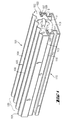
- Fig. 2 and Fig. 3 show an embodiment of the inventive Soundproofing insert, which is provided overall with the reference number 1. it includes a support part 2 and an integrally molded foot part 8.
- the support part 2 has pulled down longitudinal edges 3. Its underside 7 faces the foot part 8.
- the longitudinal edges 3 run on the side of the Support part 2 two strip-like beads 4, which fall obliquely to the longitudinal edges 3.
- the two inner beads 6 are from a material web 61 separated whose height essentially corresponds to the height of the beads 4 near the edge.
- the bearing surface of the beads 4, 6 thus has Support part 2 on a convexly curved envelope surface H.
- the envelope surface H is a track which has approximately the shape of a flat ellipse half, wherein the axial projection of the longitudinal edges 3 represent the main apex of the ellipse.
- the foot part 8 has flanks 9 which are arranged obliquely to one another and which are the underside 7 of the support part 2 are facing away.
- the one enclosed by the flanks 9 The flank angle is denoted by a and is less than 60 °.
- shoulders 10 are provided, the underside 7 of the support part 2 opposite.
- the foot part 8 has a lengthwise direction running bore 11 on.
- the bore 11 is on the support part 2 facing away Side bordered by a flexible wall part 12, which into the bore 11 is arched. Project from the walls opposite the material web 12 Projections 13 extending in the longitudinal direction into the bore 11.
- Fig. 4 shows a C-rail 15 mounted sound insulation insert 1, which a component 19 is loaded.
- the weight force exerted by the component 19 is G designated. Due to the weight G, the rim 4 is bordered by the beads 4 Center area 5 pressed into the interior of the C-profile rail 15. It is immediate can be seen that the component 19 of a large part of the bearing surface of the Sound insulation insert 1 is supported.
- the arrows T indicate that the material the soundproofing insert 1 against the edge of the opening of the rail 15 Longitudinal edges 17 is pressed. With a transverse displacement of the component 19 by the arrow S is indicated, the contact pressure of the material acts against the Longitudinal edges 17 of the rail prevent the sound insulation insert 1 from detaching.
- Fig. 5 and Fig. 6 show the soundproofing insert according to the invention in the Bore 11 located threaded bolts 20 and 21.
- Fig. 5 is a threaded bolt 20th with a smaller diameter, for example M6, held in the bore 11.
- Threaded bolt 20 is from the longitudinally extending projections 13 and the inwardly curved flexible wall part 12 held.
- Fig. 6 shows the Conditions with a threaded bolt 21, the diameter of which is as large as possible, corresponds to the diameter of the bore 11.
- the projections 13 are pressed into the wall and the flexible wall part 12 is outward turned inside out.
- the foot part 8 has an approximately circular arc-shaped outer contour.
- the coating can be applied to the entire Support area may be provided. However, as shown, for example, it can only be attached to the raised areas of the strip-shaped beads.
Landscapes
- Physics & Mathematics (AREA)
- Engineering & Computer Science (AREA)
- Acoustics & Sound (AREA)
- Multimedia (AREA)
- Railway Tracks (AREA)
- Vehicle Interior And Exterior Ornaments, Soundproofing, And Insulation (AREA)
- Cable Accessories (AREA)
- Soundproofing, Sound Blocking, And Sound Damping (AREA)
- Passenger Equipment (AREA)
- Building Environments (AREA)
Applications Claiming Priority (2)
| Application Number | Priority Date | Filing Date | Title |
|---|---|---|---|
| DE19710759A DE19710759A1 (de) | 1997-03-14 | 1997-03-14 | Schallschutzeinlage |
| DE19710759 | 1997-03-14 |
Publications (3)
| Publication Number | Publication Date |
|---|---|
| EP0865024A2 true EP0865024A2 (fr) | 1998-09-16 |
| EP0865024A3 EP0865024A3 (fr) | 2001-02-14 |
| EP0865024B1 EP0865024B1 (fr) | 2003-07-30 |
Family
ID=7823462
Family Applications (1)
| Application Number | Title | Priority Date | Filing Date |
|---|---|---|---|
| EP98810034A Expired - Lifetime EP0865024B1 (fr) | 1997-03-14 | 1998-01-22 | Insert de protection acoustique |
Country Status (4)
| Country | Link |
|---|---|
| EP (1) | EP0865024B1 (fr) |
| AT (1) | ATE246388T1 (fr) |
| DE (2) | DE19710759A1 (fr) |
| ES (1) | ES2205425T3 (fr) |
Cited By (1)
| Publication number | Priority date | Publication date | Assignee | Title |
|---|---|---|---|---|
| CN116486771A (zh) * | 2022-01-13 | 2023-07-25 | 喜利得股份公司 | 用于安装支架的隔音插件 |
Families Citing this family (1)
| Publication number | Priority date | Publication date | Assignee | Title |
|---|---|---|---|---|
| GB2590217B (en) * | 2018-06-19 | 2022-11-30 | Studco Building Systems Uk Ltd | Acoustic mount |
Family Cites Families (4)
| Publication number | Priority date | Publication date | Assignee | Title |
|---|---|---|---|---|
| GB592755A (en) * | 1943-09-14 | 1947-09-29 | Adel Prec Products Corp | Cushion for conduit and wire supporting clips |
| US3865358A (en) * | 1972-11-29 | 1975-02-11 | Jeff A Butters | Dent deflector for mobile homes |
| DE2311057B2 (de) * | 1973-03-06 | 1980-09-18 | Franz 6200 Wiesbaden Mueller | Geräuschdämmende Isoliereinlagen für Rohrschellen, Rohraufhängungen u.dgl |
| DD294667A5 (de) * | 1990-05-31 | 1991-10-10 | Paedagogische Hochschule "Dr. Theodor Neubauer" Erfurt/Muehlhausen,De | Wischerblatt fuer scheibenwischer |
-
1997
- 1997-03-14 DE DE19710759A patent/DE19710759A1/de not_active Withdrawn
-
1998
- 1998-01-22 AT AT98810034T patent/ATE246388T1/de active
- 1998-01-22 DE DE59809116T patent/DE59809116D1/de not_active Expired - Lifetime
- 1998-01-22 EP EP98810034A patent/EP0865024B1/fr not_active Expired - Lifetime
- 1998-01-22 ES ES98810034T patent/ES2205425T3/es not_active Expired - Lifetime
Cited By (1)
| Publication number | Priority date | Publication date | Assignee | Title |
|---|---|---|---|---|
| CN116486771A (zh) * | 2022-01-13 | 2023-07-25 | 喜利得股份公司 | 用于安装支架的隔音插件 |
Also Published As
| Publication number | Publication date |
|---|---|
| DE59809116D1 (de) | 2003-09-04 |
| ATE246388T1 (de) | 2003-08-15 |
| EP0865024A3 (fr) | 2001-02-14 |
| ES2205425T3 (es) | 2004-05-01 |
| DE19710759A1 (de) | 1998-09-17 |
| EP0865024B1 (fr) | 2003-07-30 |
Similar Documents
| Publication | Publication Date | Title |
|---|---|---|
| DE10142556A1 (de) | Profilierte Montageschiene | |
| EP0060567A1 (fr) | Support insonorisant | |
| EP0750090A2 (fr) | Raccord rectiligne en matière plastique pour profilés intercalaires creux de vitrages isolants | |
| EP2035635B1 (fr) | Élément d'assemblage pour profilés en c présentant un moyen de compensation et ensemble associé | |
| EP0865024B1 (fr) | Insert de protection acoustique | |
| WO2013174839A1 (fr) | Cadre d'insertion conçu pour un échangeur thermique | |
| EP1866492B1 (fr) | Profile en c et cloison de séparation à profile en c | |
| DE2702765C2 (de) | Schalldämmendes Befestigungselement | |
| EP0742404A1 (fr) | Collier de serrage avec chemise élastique | |
| EP2899392B1 (fr) | Amortisseur d'oscillations travaillant selon le principe masse-ressort | |
| DE10324160B4 (de) | Vorrichtung zum Verbinden von Flansche aufweisende Luftkanalabschnitte | |
| DE10014050C1 (de) | Vorrichtung zur Befestigung von Rohren | |
| DE202005007835U1 (de) | Rohr | |
| AT401542B (de) | Schalldämmrohr, insbesondere schalldämmrohrbogen | |
| EP2267263A2 (fr) | Joint d'étanchéité pour porte | |
| DE10213064A1 (de) | Elastomere Dichtung | |
| DE102017007324A1 (de) | Fassadenkonstruktionseinheit | |
| DE3503572C2 (fr) | ||
| DE202021102165U1 (de) | System zur Befestigung | |
| DE102009031325A1 (de) | Filterwand für raumlufttechnische Anlagen in Gebäuden | |
| DE2917350A1 (de) | Vorrichtung zum befestigen eines elementes an einem rohr | |
| EP1591597A1 (fr) | Cloison avec panneaux de gypse et montants | |
| DE102012012356A1 (de) | Verfahren zum Anbringen einer Abdeckung an einem Bauelement, sowie ein Konstruktionselement | |
| DE19953992B4 (de) | Funktionselement für Reinräume | |
| WO2007112773A1 (fr) | Dispositif de fixation d'elements de construction pour pose a sec |
Legal Events
| Date | Code | Title | Description |
|---|---|---|---|
| PUAI | Public reference made under article 153(3) epc to a published international application that has entered the european phase |
Free format text: ORIGINAL CODE: 0009012 |
|
| AK | Designated contracting states |
Kind code of ref document: A2 Designated state(s): AT CH DE ES FR GB LI NL SE |
|
| AX | Request for extension of the european patent |
Free format text: AL;LT;LV;MK;RO;SI |
|
| PUAL | Search report despatched |
Free format text: ORIGINAL CODE: 0009013 |
|
| AK | Designated contracting states |
Kind code of ref document: A3 Designated state(s): AT BE CH DE DK ES FI FR GB GR IE IT LI LU MC NL PT SE |
|
| AX | Request for extension of the european patent |
Free format text: AL;LT;LV;MK;RO;SI |
|
| RIC1 | Information provided on ipc code assigned before grant |
Free format text: 7G 10K 11/16 A, 7F 16F 1/44 B |
|
| 17P | Request for examination filed |
Effective date: 20010814 |
|
| AKX | Designation fees paid |
Free format text: AT CH DE ES FR GB LI NL SE |
|
| 17Q | First examination report despatched |
Effective date: 20020725 |
|
| GRAH | Despatch of communication of intention to grant a patent |
Free format text: ORIGINAL CODE: EPIDOS IGRA |
|
| GRAH | Despatch of communication of intention to grant a patent |
Free format text: ORIGINAL CODE: EPIDOS IGRA |
|
| GRAA | (expected) grant |
Free format text: ORIGINAL CODE: 0009210 |
|
| AK | Designated contracting states |
Designated state(s): AT CH DE ES FR GB LI NL SE |
|
| REG | Reference to a national code |
Ref country code: GB Ref legal event code: FG4D Free format text: NOT ENGLISH |
|
| REG | Reference to a national code |
Ref country code: CH Ref legal event code: EP |
|
| REG | Reference to a national code |
Ref country code: SE Ref legal event code: TRGR |
|
| REF | Corresponds to: |
Ref document number: 59809116 Country of ref document: DE Date of ref document: 20030904 Kind code of ref document: P |
|
| GBT | Gb: translation of ep patent filed (gb section 77(6)(a)/1977) |
Effective date: 20031114 |
|
| REG | Reference to a national code |
Ref country code: ES Ref legal event code: FG2A Ref document number: 2205425 Country of ref document: ES Kind code of ref document: T3 |
|
| ET | Fr: translation filed | ||
| PLBE | No opposition filed within time limit |
Free format text: ORIGINAL CODE: 0009261 |
|
| STAA | Information on the status of an ep patent application or granted ep patent |
Free format text: STATUS: NO OPPOSITION FILED WITHIN TIME LIMIT |
|
| 26N | No opposition filed |
Effective date: 20040504 |
|
| REG | Reference to a national code |
Ref country code: FR Ref legal event code: PLFP Year of fee payment: 19 |
|
| PGFP | Annual fee paid to national office [announced via postgrant information from national office to epo] |
Ref country code: FR Payment date: 20151208 Year of fee payment: 19 Ref country code: ES Payment date: 20151214 Year of fee payment: 19 |
|
| PGFP | Annual fee paid to national office [announced via postgrant information from national office to epo] |
Ref country code: NL Payment date: 20160111 Year of fee payment: 19 |
|
| PGFP | Annual fee paid to national office [announced via postgrant information from national office to epo] |
Ref country code: DE Payment date: 20160119 Year of fee payment: 19 Ref country code: CH Payment date: 20160111 Year of fee payment: 19 |
|
| PGFP | Annual fee paid to national office [announced via postgrant information from national office to epo] |
Ref country code: GB Payment date: 20160120 Year of fee payment: 19 Ref country code: AT Payment date: 20151223 Year of fee payment: 19 Ref country code: SE Payment date: 20160112 Year of fee payment: 19 |
|
| REG | Reference to a national code |
Ref country code: DE Ref legal event code: R119 Ref document number: 59809116 Country of ref document: DE |
|
| REG | Reference to a national code |
Ref country code: CH Ref legal event code: PL |
|
| REG | Reference to a national code |
Ref country code: NL Ref legal event code: MM Effective date: 20170201 |
|
| REG | Reference to a national code |
Ref country code: AT Ref legal event code: MM01 Ref document number: 246388 Country of ref document: AT Kind code of ref document: T Effective date: 20170122 |
|
| GBPC | Gb: european patent ceased through non-payment of renewal fee |
Effective date: 20170122 |
|
| REG | Reference to a national code |
Ref country code: FR Ref legal event code: ST Effective date: 20170929 |
|
| PG25 | Lapsed in a contracting state [announced via postgrant information from national office to epo] |
Ref country code: FR Free format text: LAPSE BECAUSE OF NON-PAYMENT OF DUE FEES Effective date: 20170131 Ref country code: LI Free format text: LAPSE BECAUSE OF NON-PAYMENT OF DUE FEES Effective date: 20170131 Ref country code: CH Free format text: LAPSE BECAUSE OF NON-PAYMENT OF DUE FEES Effective date: 20170131 Ref country code: AT Free format text: LAPSE BECAUSE OF NON-PAYMENT OF DUE FEES Effective date: 20170122 |
|
| PG25 | Lapsed in a contracting state [announced via postgrant information from national office to epo] |
Ref country code: NL Free format text: LAPSE BECAUSE OF NON-PAYMENT OF DUE FEES Effective date: 20170201 Ref country code: GB Free format text: LAPSE BECAUSE OF NON-PAYMENT OF DUE FEES Effective date: 20170122 Ref country code: DE Free format text: LAPSE BECAUSE OF NON-PAYMENT OF DUE FEES Effective date: 20170801 Ref country code: SE Free format text: LAPSE BECAUSE OF NON-PAYMENT OF DUE FEES Effective date: 20170123 |
|
| REG | Reference to a national code |
Ref country code: ES Ref legal event code: FD2A Effective date: 20180507 |
|
| PG25 | Lapsed in a contracting state [announced via postgrant information from national office to epo] |
Ref country code: ES Free format text: LAPSE BECAUSE OF NON-PAYMENT OF DUE FEES Effective date: 20170123 |