EP0865139B1 - Leistungsflussregler mit Drehtransformatoren - Google Patents
Leistungsflussregler mit Drehtransformatoren Download PDFInfo
- Publication number
- EP0865139B1 EP0865139B1 EP98301775A EP98301775A EP0865139B1 EP 0865139 B1 EP0865139 B1 EP 0865139B1 EP 98301775 A EP98301775 A EP 98301775A EP 98301775 A EP98301775 A EP 98301775A EP 0865139 B1 EP0865139 B1 EP 0865139B1
- Authority
- EP
- European Patent Office
- Prior art keywords
- phase shifting
- winding
- shifting transformer
- rotary phase
- transformer
- Prior art date
- Legal status (The legal status is an assumption and is not a legal conclusion. Google has not performed a legal analysis and makes no representation as to the accuracy of the status listed.)
- Expired - Lifetime
Links
Images


Classifications
-
- H—ELECTRICITY
- H01—ELECTRIC ELEMENTS
- H01F—MAGNETS; INDUCTANCES; TRANSFORMERS; SELECTION OF MATERIALS FOR THEIR MAGNETIC PROPERTIES
- H01F38/00—Adaptations of transformers or inductances for specific applications or functions
- H01F38/18—Rotary transformers
-
- H—ELECTRICITY
- H02—GENERATION; CONVERSION OR DISTRIBUTION OF ELECTRIC POWER
- H02J—ELECTRIC POWER NETWORKS; CIRCUIT ARRANGEMENTS OR SYSTEMS FOR SUPPLYING OR DISTRIBUTING ELECTRIC POWER; SYSTEMS FOR STORING ELECTRIC ENERGY
- H02J3/00—Circuit arrangements for AC mains or AC distribution networks
- H02J3/04—Arrangements for connecting networks of the same frequency but supplied from different sources
- H02J3/06—Controlling the transfer of power between connected networks; Controlling load sharing between connected networks
-
- H—ELECTRICITY
- H02—GENERATION; CONVERSION OR DISTRIBUTION OF ELECTRIC POWER
- H02J—ELECTRIC POWER NETWORKS; CIRCUIT ARRANGEMENTS OR SYSTEMS FOR SUPPLYING OR DISTRIBUTING ELECTRIC POWER; SYSTEMS FOR STORING ELECTRIC ENERGY
- H02J3/00—Circuit arrangements for AC mains or AC distribution networks
- H02J3/18—Arrangements for adjusting, eliminating or compensating reactive power in networks
- H02J3/1821—Arrangements for adjusting, eliminating or compensating reactive power in networks using shunt compensators
- H02J3/1828—Arrangements for adjusting, eliminating or compensating reactive power in networks using shunt compensators with stepwise control, e.g. switched capacitor banks
-
- H—ELECTRICITY
- H02—GENERATION; CONVERSION OR DISTRIBUTION OF ELECTRIC POWER
- H02J—ELECTRIC POWER NETWORKS; CIRCUIT ARRANGEMENTS OR SYSTEMS FOR SUPPLYING OR DISTRIBUTING ELECTRIC POWER; SYSTEMS FOR STORING ELECTRIC ENERGY
- H02J3/00—Circuit arrangements for AC mains or AC distribution networks
- H02J3/34—Arrangements for transfer of electric power between networks of substantially different frequency
-
- H—ELECTRICITY
- H02—GENERATION; CONVERSION OR DISTRIBUTION OF ELECTRIC POWER
- H02K—DYNAMO-ELECTRIC MACHINES
- H02K47/00—Dynamo-electric converters
- H02K47/18—AC/AC converters
- H02K47/22—Single-armature frequency converters with or without phase-number conversion
-
- H—ELECTRICITY
- H02—GENERATION; CONVERSION OR DISTRIBUTION OF ELECTRIC POWER
- H02P—CONTROL OR REGULATION OF ELECTRIC MOTORS, ELECTRIC GENERATORS OR DYNAMO-ELECTRIC CONVERTERS; CONTROLLING TRANSFORMERS, REACTORS OR CHOKE COILS
- H02P9/00—Arrangements for controlling electric generators for the purpose of obtaining a desired output
- H02P9/48—Arrangements for obtaining a constant output value at varying speed of the generator, e.g. on vehicle
-
- H—ELECTRICITY
- H02—GENERATION; CONVERSION OR DISTRIBUTION OF ELECTRIC POWER
- H02P—CONTROL OR REGULATION OF ELECTRIC MOTORS, ELECTRIC GENERATORS OR DYNAMO-ELECTRIC CONVERTERS; CONTROLLING TRANSFORMERS, REACTORS OR CHOKE COILS
- H02P2101/00—Special adaptation of control arrangements for generators
- H02P2101/10—Special adaptation of control arrangements for generators for water-driven turbines
-
- Y—GENERAL TAGGING OF NEW TECHNOLOGICAL DEVELOPMENTS; GENERAL TAGGING OF CROSS-SECTIONAL TECHNOLOGIES SPANNING OVER SEVERAL SECTIONS OF THE IPC; TECHNICAL SUBJECTS COVERED BY FORMER USPC CROSS-REFERENCE ART COLLECTIONS [XRACs] AND DIGESTS
- Y02—TECHNOLOGIES OR APPLICATIONS FOR MITIGATION OR ADAPTATION AGAINST CLIMATE CHANGE
- Y02E—REDUCTION OF GREENHOUSE GAS [GHG] EMISSIONS, RELATED TO ENERGY GENERATION, TRANSMISSION OR DISTRIBUTION
- Y02E40/00—Technologies for an efficient electrical power generation, transmission or distribution
- Y02E40/10—Flexible AC transmission systems [FACTS]
-
- Y—GENERAL TAGGING OF NEW TECHNOLOGICAL DEVELOPMENTS; GENERAL TAGGING OF CROSS-SECTIONAL TECHNOLOGIES SPANNING OVER SEVERAL SECTIONS OF THE IPC; TECHNICAL SUBJECTS COVERED BY FORMER USPC CROSS-REFERENCE ART COLLECTIONS [XRACs] AND DIGESTS
- Y02—TECHNOLOGIES OR APPLICATIONS FOR MITIGATION OR ADAPTATION AGAINST CLIMATE CHANGE
- Y02E—REDUCTION OF GREENHOUSE GAS [GHG] EMISSIONS, RELATED TO ENERGY GENERATION, TRANSMISSION OR DISTRIBUTION
- Y02E40/00—Technologies for an efficient electrical power generation, transmission or distribution
- Y02E40/30—Reactive power compensation
Definitions
- This invention pertains to the transmission of power between electrical systems or electrical areas, and particularly to power flow apparatus and method for controlling the transmission of power.
- a conventional phase shifting transformer has been utilized to inject a voltage, with the voltages in the two electrical areas being shifted in phase but having the same amplitude.
- a conventional phase shifting transformer typically comprises a series transformer connected between the two electrical areas, a regulating transformer (having an exciting winding coil connected to a series winding of the series transformer), and a switching network (connected to a regulating winding of the regulating transformer and to an excited winding of the series transformer).
- the switching network comprises tap changers which have a number of discrete values.
- US Patent 5,166,597 to Larsen et al. shows various techniques for improving conventional phase shifting transformers.
- the switching network is augmented with thyristor valves to overcome problems with mechanical switches.
- reactive components are included to provide some additional control over the injected voltage.
- the series injected voltage remains in quadrature with the regulating voltage such that the effective turns ratio V 2 /V 1 equals 1.00.
- US Patent 5,343,139 to Gyugyi et al. discloses a universal power flow controller which utilizes large power-electronic converters to inject a series voltage of arbitrary magnitude and angle with respect to the regulating voltage. The net result is an effective phase shift and magnitude ratio between the two sides of the device which can be set at any value within a circle shown as Fig. 2 of that patent.
- controllers with large power-electronic converters are complex, have large physical size, and present issues of harmonics.
- What is needed therefore, and an object of the present invention is a simplified and effective technique for regulating power flow on a transmission path between two electrical areas, and which provides a desired voltage magnitude ratio as well as a desired phase shift.
- a power flow controller connected on a transmission path between a first electrical area and a second electrical area, a first side of the transmission path being connected to the first electrical area
- the apparatus comprising: a series transformer having a series winding and an excited winding, the series winding connected on the transmission path between the first electrical area and the second electrical area; a regulating transformer having an exciting winding and a regulating winding, the exciting winding connected between the series winding of the series transformer and ground; and a first rotary phase shifting transformer having a first rotary phase shifting transformer first winding and a first rotary phase shifting transformer second winding; a second rotary phase shifting transformer having a second rotary phase shifting transformer first winding and a second rotary phase shifting transformer second winding; wherein the regulating winding of the regulation transformer is connected in parallel to the first rotary phase shifting transformer first winding and the second rotary phase shifting transformer first winding and wherein the first rotary phase shifting transformer second winding, the second rotary phase shifting transformer second winding and the
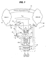
- Fig. 1 shows a power flow controller 20 on a transmission path or line 22 between a first electrical area or network 24 and a second electrical area or network 26.
- Transmission path 22 can be just one of a plurality of transmission paths connecting areas 24 and 26, other (parallel) transmission paths 23 being also shown in Fig. 1 .
- Network 24 has a voltage V 1 ; network 26 has a voltage V 2 .
- power flow controller 20 allows an operator to select both the real and reactive power flow into network 26 by injecting a voltage V ser in series on transmission path 22.
- Transmission line 22 is a three-phase line.
- Voltage transducer 36 senses the voltage V 2 in network 26.
- Current transducer 38 measures current I 2 flowing to network 26.
- a current I 1 flows from network 24 to power flow controller 20.
- power flow controller 20 comprises a series transformer 40; a regulating transformer 42; a rotary phase shifting transformer network 44; and, a control system 46, each of which are described in more detail below.
- Series transformer 40 includes a series winding 50 in series with transmission line 22 and an excited winding 52. Excited winding 52 is connected in a rotated delta configuration, as indicated by the triangle with curved arrow 54 appearing proximate winding 52.
- a connection 56 is illustrated as being situated on an input side of series winding 50, although connection 56 could be on either side or center connected to series winding 50. Alternatively, connection 56 could be to some point in first electrical area 24 or in second electrical area 26. In any of these configurations, connection 56 is said to occur on a first side of transmission path 22 and has the voltage V 1 , and thus the first side is said to be connected to the first electrical area.
- Regulating transformer 42 includes an exciting winding 60 and a regulating winding 62. Exciting winding 60 is connected between connection 56 of series transformer 40 and ground and carries a current I R . Regulating winding 62 is connected to rotary phase shifting transformer network 44 in the manner discussed below.
- Rotary phase shifting transformer network 44 comprises first rotary phase shifting transformer 102 1 and second rotary phase shifting transformer 102 2 .
- first terminals of each of first rotary phase shifting transformer 102 1 and second rotary phase shifting transformer 102 2 are connected in parallel to regulating winding 62 of regulating transformer 42.
- Second terminals of each of first rotary phase shifting transformer 102 1 and second rotary phase shifting transformer 102 2 are connected in series with excited winding 52 of series transformer 40.
- a discussion of a rotary phase shifting transformer is first provided.
- An exemplary one of the rotary phase shifting transformers referenced generically in unsubscripted manner simply as transformer 102 for convenience, is shown in Fig. 2 for describing details of each of transformers 102 1 and 102 2 .
- rotary phase shifting transformer 102 includes both a rotary transformer assembly 105 and a torque control unit 106 (also known as the rotor drive section).
- Rotary transformer assembly 105 includes both a rotor subassembly 110 and a stator 112.
- Rotor subassembly 110 includes collector rings 114 (also known as slip rings) and rotor cage section 116.
- Three-phase lines RA, RB, RC are connected to collector rings 114;
- three-phase lines SA, SB, and SC are connected to stator 112 (the A, B, and C representing corresponding one of the three phase lines; the "R” referring to rotor and the "S” referring to stator).
- Rotary phase shifting transformer 102 has a torque control amplifier 150. Power is supplied to torque control amplifier 150 by torque control power source 152.
- rotary transformer assembly 105 is wound with sixty degree phase belts, with rotor windings being labeled as RA+, RC-, RB+, RA-, RC+, and RB- and stator windings labeled as SA+, SC-, SB+, SA-, SC+, and SB-. It should be understood that the invention is not limited to a sixty degree phase belt-wound system, rather the principles of the invention are applicable for rotary transformer assemblies of pole number two and greater.
- Rotor assembly 110 is rotatable about its axis RX in both clockwise direction CW and counter-clockwise direction CCW. Rotation of rotor assembly 110 is effected by rotor drive section 106.
- Rotor drive section 106 is shown symbolically in Fig. 2 as a cylindrical section mounted on rotor assembly 110. Thus, rotor drive section 106 of Fig. 2 generally depicts various alternative and different types of drive mechanisms for causing rotation of rotor assembly 110.
- the rotary phase shifting transformer 102 has a current flow and voltage across each illustrated winding, as follows. For example, a current I RA flows in winding RA+; current I SA flows in winding SA+. A voltage V RA is across winding RA+; and a voltage V SA is across winding SA+.
- Rotor subassembly 110 has a torque T M about axis RX. At the time shown in Fig. 2 , rotor 110 and stator 112 are offset by a phase angle ⁇ RM related to the angular position of rotor 110.
- the magnitude of the rotor voltage V R and stator voltage Vs is fixed and independent of the angular position of rotor 110.
- the phase angle between rotor voltage V R and stator voltage V s is equal to the angular position ⁇ RM of rotor 110 relative to stator 112 for a single rotary phase shifting transformer 102.
- each of transformer windings (including excited winding 52 and regulating winding 62) are connected to three phase lines. Further, these three phase lines are connected to appropriate and corresponding ones of the A, B, or C windings of either rotor 110 or stator 112, as the case may be.
- first terminals of each of first rotary phase shifting transformer 102 1 and second rotary phase shifting transformer 102 2 are connected in parallel to regulating winding 62 of regulating transformer 42.
- the first terminals of transformers 102 1 and 102 2 are the stators (i.e., the windings of stator 112) of each of the transformers. That is, the three phase line connected to regulating winding 62 is connected so that the phase A line is connected to the stator windings A of both transformers 102 1 and 102 2 , so that the phase B line is connected to the stator windings B of both transformers 102 1 and 102 2 , and so forth.
- Fig. 1 only one line of the three phase line is shown, and only one winding is depicted about the stator and rotor, although it should be understood that six windings occur for each of the stator and rotor.
- Second terminals of transformers 102 1 and 102 2 are connected in series with excited winding 52 of series transformer 40.
- the second terminals are the rotors of transformers 102 1 and 102 2 . Therefore, the three phase line connected to excited winding 52 has its three lines connected to respective ones of the rotor windings of transformer 102 2 , with the rotor windings of transformer 102 2 being in turn connected to respective ones of the rotor windings of transformer 102 1 , with the rotor windings of transformer 102 1 being connected by the respective three lines back to excited winding 52 of series transformer 40.
- Fig. 1 shows the stator windings as being the first terminals of transformers 102 1 and 102 2 and the rotor windings as being the second terminals, it should be appreciated that such terminal assignment can be reversed. That is, in an alternate embodiment, the rotor windings can be connected in parallel to regulating winding 62 of regulating transformer 42 and the stator windings can be connected in series with excited winding 52 of series transformer 40.
- control system 46 includes both a high-level controller 200 and a position controller 202.
- High-level controller 200 is connected to voltage transducer 36 (to receive the value of V 2 ) and to current transducer 38 (to receive the value of current I 2 ). Further, high-level controller 200 receives two operator set point input signals, specifically a real power order signal P 0 and a reactive power order signal Q 0 indicative of the real and reactive power requirements of second electrical area 26.
- Setting order (input) signals P 0 and Q 0 can be accomplished by adjusting a knob or inputting data at an operator control panel or operator workstation, which may be proximate or remote to controller 200.
- control system 46 is to regulate real and reactive power flow into area 26.
- real power order signal P 0 and the reactive power order signal Q 0 as well as the transduced values of V 2 and I 2 , high-level controller 200 generates the signals T PFC and ⁇ PFC which are applied on lines 214 and 216, respectively, to position controller 202.
- Signals T PFC and ⁇ PFC are the desired effective voltage magnitude ratio and phase shift ⁇ PFC between first electrical area 24 and second electrical area 26, generated by the power flow controller 20. It is well known in the art that operating on these two components will permit effective regulation of real and reactive power flow, respectively.
- Fig. 5 One embodiment of high-level controller 200 is shown in Fig. 5 .
- the controller 200 of Fig. 5 receives the inputs V 2 and I 2 at power transducer 300, and generates signals Q 2 and P 2 .
- Signal Q 2 is applied to a negative terminal of error-summing element 302; the operator input signal Q 0 is applied to a positive terminal of error-summing element 302.
- Error-summing element 302 outputs a value indicative of the sum of Q 0 - Q 2 to proportional-plus-integral (P-I) regulator 304, which in turn outputs the signal T PFC on line 214 in the manner aforedescribed.
- P-I proportional-plus-integral
- signal P 2 is applied to a negative terminal of error-summing element 312; the operator input signal Q 0 is applied to a positive terminal of error-summing element 312.
- Error-summing element 312 outputs a value indicative of the sum of Po - P 2 to P-I regulator 314, which in turn outputs the signal O PFC on line 216 in the manner aforedescribed.
- real and reactive power flow is transduced via well-known prior art element 300 based on a measure of voltage and current on one side of the rotary phase frequency transformer network 44 (e.g, in network 26). These measured flow signals are compared to the setpoints, e.g., the order signals Q 0 , P 0 , established by the system operator in error-summing elements. The errors are then amplified by conventional regulator function, such as a proportional-integral type regulators 304, 314, which adjusts the commands for phase shift ( ⁇ PFC ) and magnitude ratio (T PFC ) of the rotary phase frequency transformers 102.
- ⁇ PFC phase shift
- T PFC magnitude ratio
- position controller 202 uses signals T PFC and ⁇ PFC , position controller 202 computes the corresponding ratio of V E /V 1 and the relative angle ⁇ E between the regulating voltage V RR and the exciting voltage V E , and then determines the necessary phase angle ⁇ E1 for transformer 102 1 and phase angle ⁇ EZ for transformer 102 2 to meet the desired values of ratio V E /V 1 and relative angle ⁇ E .
- Fig. 3 and Fig. 4 together with the equations hereinafter discussed, explain e.g., how position controller 202 determines the phase angles ⁇ E1 and ⁇ E2 for transformers 102 1 and 102 2 , respectively.
- Fig. 4 is an overall phasor diagram for power flow controller 20. The voltage V ser across power flow controller 20 is illustrated both in Fig. 1 and in Fig 4 . In Fig. 4 it is assumed that series transformer 40 has unity turns ratio and a 90° electrical rotation between V and V E .
- T PFC and ⁇ PFC on lines 214 and 216 are defined in the following manner T PFC is the magnitude of the ratio of V 2 /V 1 ; ⁇ PFC is the phase angle by which V 2 leads V 1 .
- V ser / V 1 ( T PFC ⁇ cos ⁇ PFC - 1 ) + j T PFC ⁇ sin ⁇ PFC
- V E / V 1 ( T PFC ⁇ sin ⁇ PFC ) + j ⁇ 1 - T PFC ⁇ cos ⁇ PFC
- the above phasor between V E and V 1 (Eqn. 2) is readily converted to polar form yielding a magnitude and angle to form the signals ratio V E /V 1 , and relative angle ⁇ E .
- Fig. 6 is a phasor diagram for the two rotary transformers 102 1 and 102 2 .
- V RR is the voltage across regulating winding 62 of regulating transformer 42.
- the magnitudes of the voltages V E1 and V E2 are constant, by changing the phase angles ⁇ E1 and ⁇ EZ , the magnitude of the resultant voltage vector V E as well as its phase ⁇ E can be selectively changed to meet the demands of the inputted order signals.
- Regulating transformer 42 and the rotary phase shifting transformers 102 have non-unity turns ratios T 1R and T RE , respectively, in accordance with Equation 3 and Equation 4:
- T 1 ⁇ R V RR / V 1
- phase angles ⁇ E1 and ⁇ E2 that are applied to torque control amplifers 150 of transformers 102, and 102 2 , respectively (see Fig. 2 ).
- torque control amplifier 150 outputs three phase signals TA, TB, and TC to torque control unit 106.
- TA refers collectively to TA+ and TA-
- TB refers collectively to TB+ and TB-, and so forth.
- control system 46 sets the values of phase angles ⁇ E1 and ⁇ E2 for transformers 102 1 and 102 2 , respectively, in order to obtain the desired effective phase shift ⁇ PFC and voltage magnitude ratio T PFC between the first electrical area 24 and the second electrical area 26 in accordance with the operator input signals Po and Q 0 .
- high-level controller 200 may perform many different functions, depending upon the needs of the overall power system. A likely use is to regulate real and reactive power flow through the line which includes the power flow converter 20 described above.
- controllers 200 and 202 of Fig. 1 can be performed in various ways and elements, e.g., by microprocessors. Further, it should be understood that one microprocessor or circuit can perform both the functions of controller 200 and 202, although in the foregoing the functions have been illustrated as being performed by two separate controllers.
- Fig. 1A shows another embodiment of a power flow controller 20', also situated on transmission path or line 22 between first electrical area or network 24 and second electrical area or network 26.
- power flow controller 20' of Fig. 1A also has two rotary transformers 102 1 and 102 2 .
- Power flow controller 20' has first terminals of the rotary transformers 102 1 and 102 2 connected in parallel and second terminals of rotary transformers 102 1 and 102 2 connected in series.
- the power flow controller 20' does not require series transformer 40 and regulating transformer 42. Rather, second terminals of second terminals of rotary transformers 102 1 and 102 2 connected in series along transmission path or line 22. First terminals of the rotary transformers 102 1 and 102 2 are connected in parallel to connection node 56, node 56 being on a first side of transmission path 22 and being at voltage magnitude V 1 of first electrical area 24.
- connection node 56 node 56 being on a first side of transmission path 22 and being at voltage magnitude V 1 of first electrical area 24.
- the first side of transmission path 22 can refer to a connection such as that shown for node 56, or connection to or internal to first electrical area 24 or second electrical area 26.
- control system 46 of power flow controller 20' is essentially identical to that aforedescribed with respect to power flow controller 20 of Fig. 1 .
- rotor drive section 106 includes an actuator and some type of linkage (e.g., gearing) which interfaces with rotor assembly 110.
- rotor drive section 106 comprises a worm gear drive arrangement.
- rotor drive section 106 comprises an actuator such as a stepper motor acting through a radial (e.g, spur) gear, a direct drive arrangement, a hydraulic actuator turning a gear on rotor assembly 110, or a pneumatic actuator turning a gear on rotor assembly 110.
- the function of the torque control unit is accomplished by providing two sets of windings on both the rotor and the stator, a first set of windings on the rotor and stator having a different number of poles (e.g., 2 poles) than a second set of windings on the rotor and stator (e.g., 4 or more poles).
- a first set of windings on the rotor and stator having a different number of poles (e.g., 2 poles) than a second set of windings on the rotor and stator (e.g., 4 or more poles).
- connection to rotor subassembly 110 has been described in connection with what is presently considered to be the most practical and preferred embodiment, it is to be understood that the invention is not to be limited to the disclosed embodiment.
- connection to rotor subassembly 110 has shown connection to rotor subassembly 110 as being accomplished using collector rings 114, it should also be understood that other forms of connection, including flexible wiring, may instead by utilized.
Landscapes
- Engineering & Computer Science (AREA)
- Power Engineering (AREA)
- Supply And Distribution Of Alternating Current (AREA)
- Ac-Ac Conversion (AREA)
- Control Of Eletrric Generators (AREA)
- Incineration Of Waste (AREA)
- Control Of Electrical Variables (AREA)
Claims (10)
- Leistungsflussregler, der mit einem Übertragungsweg zwischen einem ersten elektrischen Bereich (1) und einem zweiten elektrischen Bereich (2) verbunden ist, wobei eine erste Seite des Übertragungsweges (22) mit dem ersten elektrischen Bereich verbunden ist, und die Vorrichtung aufweist:einen Reihentransformator (40) mit einer Reihenwicklung (50) und einer erregten Wicklung (52), wobei die Reihenwicklung (50) in den Übertragungsweg zwischen dem ersten elektrischen Bereich und dem zweiten elektrischen Bereich geschaltet ist;einen Regelungstransformator (42) mit einer Erregungswicklung (60) und einer Regelungswicklung (62), wobei die Erregungswicklung (60) zwischen die Reihenwicklung (50) des Reihentransformators (42) und Erde geschaltet ist; undeinen ersten Drehphasenschiebertransformator (1021) mit einer ersten Wicklung des ersten Drehphasenschiebertransformators und einer zweiten Wicklung des ersten Drehphasenschiebertransformators;einen zweiten Drehphasenschiebertransformator (1022) mit einer ersten Wicklung des zweiten Drehphasenschiebertransformators und einer zweiten Wicklung des zweiten Drehphasenschiebertransformators;wobei die Regelungswicklung (62) des Regelungstransformators (42) zu der ersten Wicklung des ersten Drehphasenschiebertransformators und der ersten Wicklung des zweiten Drehphasenschiebertransformators parallel geschaltet ist und wobei die zweite Wicklung des ersten Drehphasenschiebertransformators, die zweite Wicklung des zweiten Drehphasenschiebertransformators und die erregte Wicklung (52) des Reihentransformators (40) alle in Reihe geschaltet sind; undein Regelsystem (46) zum Anlegen von Regelsignalen an den ersten Drehphasenschiebertransformator (1021) und den zweiten Drehphasenschiebertransformator (1022), wodurch eine effektive Phasenverschiebung (θPFC) und ein Spannungsgrößenverhältnis (TPFC) zwischen dem ersten elektrischen Bereich und dem zweiten elektrischen Bereich erzeugt werden.
- Leistungsflussregler nach Anspruch 1, wobei das Regelsystem (46) die Regelsignale anlegt, um unabhängig eine effektive Phasenverschiebung und ein Spannungsgrößenverhältnis zwischen dem ersten elektrischen Bereich (1) und dem zweiten elektrischen Bereich (2) zu erzeugen.
- Leistungsflussregler, der mit einem Übertragungsweg zwischen einem ersten elektrischen Bereich (1) und einem zweiten elektrischen Bereich (2) verbunden ist, wobei eine erste Seite des Übertragungsweges (22) mit dem ersten elektrischen Bereich verbunden ist, und die Vorrichtung aufweist:einen ersten Drehphasenschiebertransformator (1021) mit einer ersten Wicklung des ersten Drehphasenschiebertransformators und einer zweiten Wicklung des ersten Drehphasenschiebertransformators;einen zweiten Drehphasenschiebertransformator (1022) mit einer ersten Wicklung des zweiten Drehphasenschiebertransformators und einer zweiten Wicklung des zweiten Drehphasenschiebertransformators;wobei die erste Wicklung des ersten Drehphasenschiebertransformators und die erste Wicklung des zweiten Drehphasenschiebertransformators parallel geschaltet sind und wobei die zweite Wicklung des ersten Drehphasenschiebertransformators und die zweite Wicklung des zweiten Drehphasenschiebertransformators Reihe in den Übertragungsweg geschaltet sind; undein Regelsystem (46) zum Anlegen von Regelsignalen an den ersten Drehphasenschiebertransformator (1021) und den zweiten Drehphasenschiebertransformator (1022), wodurch eine effektive Phasenverschiebung (θPFC) und ein Spannungsgrößenverhältnis (TPFC) zwischen dem ersten elektrischen Bereich und dem zweiten elektrischen Bereich erzeugt werden.
- Leistungsflussregler nach Anspruch 1 oder 3, wobei sowohl der erste Drehphasenschiebertransformator (1021) als auch der zweite Drehphasenschiebertransformator (1022) einen Rotor und einen Stator besitzen, ein Spannungszeiger des Rotors und Stators des ersten Drehphasenschiebertransformators (1021) um einen Phasenwinkel θE1 in Bezug auf eine Winkelposition des Rotors des ersten Drehphasenschiebertransformators (1021) verschoben ist, ein Spannungszeiger des Rotors und Stators des zweiten Drehphasenschiebertransformators (1022) um einen Phasenwinkel θE2 in Bezug auf eine Winkelposition des Rotors des ersten Drehphasenschiebertransformators (1021) verschoben ist, und wobei Sollwerte des Phasenwinkels θE1 und des Phasenwinkels θE2 jeweils durch das Regelsystem an den ersten Drehphasenschiebertransformator (1021) und den zweiten Drehphasenschiebertransformator (1022) angelegt werden.
- Verfahren zum Regeln des Leistungsflusses auf einem Übertragungsweg zwischen einem ersten elektrischen Bereich (1) und einem zweiten elektrischen Bereich (2), wobei eine erste Seite des Übertragungsweges (22) mit dem ersten elektrischen Bereich verbunden ist, und das Verfahren die Schritte aufweist:Verbinden eines Reihentransformators (40) mit einer Reihenwicklung (50) und einer erregten Wicklung (52) mit der Reihenwicklung (50) in dem Übertragungsweg zwischen dem ersten elektrischen Bereich und dem zweiten elektrischen Bereich;Verbinden eines Regelungstransformators (42) mit einer Erregungswicklung (60) und einer Regelungswicklung (62) mit der Erregungswicklung (60) zwischen der Reihenwicklung (50) des Reihentransformators (42) und Erde; undBereitstellen eines ersten Drehphasenschiebertransformators (1021) mit einer ersten Wicklung des ersten Drehphasenschiebertransformators und einer zweiten Wicklung des ersten Drehphasenschiebertransformators und eines zweiten Drehphasenschiebertransformators (1022) mit einer ersten Wicklung des zweiten Drehphasenschiebertransformators und einer zweiten Wicklung des zweiten Drehphasenschiebertransformators;Parallelschalten der Regelungswicklung (62) des Regelungstransformators (42) zu der ersten Wicklung des ersten Drehphasenschiebertransformators und der ersten Wicklung des zweiten Drehphasenschiebertransformators und in Reihe schalten der zweiten Wicklung des ersten Drehphasenschiebertransformators, der zweiten Wicklung des zweiten Drehphasenschiebertransformators und der erregten Wicklung (52) des Reihentransformators (40); undAnlegen von Regelsignalen an den ersten Drehphasenschiebertransformator (1021) und den zweiten Drehphasenschiebertransformator (1022), wodurch eine effektive Phasenverschiebung (θPFC) und ein Spannungsgrößenverhältnis (TPFC) zwischen dem ersten elektrischen Bereich und dem zweiten elektrischen Bereich erzeugt werden.
- Verfahren nach Anspruch 5, wobei der Schritt der Verbindung der Regelungswicklung (62) des Regelungstransformators (42) mit der ersten Wicklung des Drehphasenschiebertransformators (1021) eine Parallelschaltung der Regelungswicklung des Regelungstransformators zu ersten Wicklungen von wenigstens zwei Drehphasenschiebertransformatoren, einer zweiten Wicklung des ersten Drehphasenschiebertransformators und einer zweiten Wicklung des zweiten Drehphasenschiebertransformators, die mit der erregten Wicklung (52) des Reihentransformators (40) in Reihe geschaltet ist, beinhaltet.
- Verfahren zum Regeln des Leistungsflusses auf einem Übertragungsweg zwischen einem ersten elektrischen Bereich (1) und einem zweiten elektrischen Bereich (2), wobei eine erste Seite des Übertragungsweges (22) mit dem ersten elektrischen Bereich verbunden ist, und das Verfahren die Schritte aufweist:Bereitstellen eines ersten Drehphasenschiebertransformators (1021) mit einer ersten Wicklung des ersten Drehphasenschiebertransformators und einer zweiten Wicklung des ersten Drehphasenschiebertransformators und eines zweiten Drehphasenschiebertransformators (1022) mit einer ersten Wicklung des zweiten Drehphasenschiebertransformators und einer zweiten Wicklung des zweiten Drehphasenschiebertransformators;Parallelschalten der ersten Wicklung des ersten Drehphasenschiebertransformators und der ersten Wicklung des zweiten Drehphasenschiebertransformators und in Reihe schalten der zweiten Wicklung des ersten Drehphasenschiebertransformators, der zweiten Wicklung des zweiten Drehphasenschiebertransformators in dem Übertragungsweg; undAnlegen von Regelsignalen an den ersten Drehphasenschiebertransformator (1021) und den zweiten Drehphasenschiebertransformator (1022), wodurch eine effektive Phasenverschiebung (θPFC) und ein Spannungsgrößenverhältnis (TPFC) zwischen dem ersten elektrischen Bereich und dem zweiten elektrischen Bereich erzeugt werden.
- Verfahren nach Anspruch 7, wobei die Regelsignale angelegt werden, um unabhängig die effektive Phasenverschiebung und das Spannungsgrößenverhältnis zwischen dem ersten elektrischen Bereich (1) und dem zweiten elektrischen Bereich (2) zu erzielen.
- Verfahren nach Anspruch 7, wobei sowohl der erste Drehphasenschiebertransformator (1021) als auch der zweite Drehphasenschiebertransformator (1022) einen Rotor und einen Stator besitzen, ein Spannungszeiger des Rotors und Stators des ersten Drehphasenschiebertransformators (1021) um einen Phasenwinkel θE1 in Bezug auf eine Winkelposition des Rotors des ersten Drehphasenschiebertransformators (1021) verschoben ist, ein Spannungszeiger des Rotors und Stators des zweiten Drehphasenschiebertransformators (1022) um einen Phasenwinkel θE2 in Bezug auf eine Winkelposition des Rotors des ersten Drehphasenschiebertransformators (1021) verschoben ist, und wobei Sollwerte des Phasenwinkels θE1 und des Phasenwinkels θE2 jeweils durch das Regelsystem an den ersten Drehphasenschiebertransformator (1021) und den zweiten Drehphasenschiebertransformator (1022) angelegt werden, und wobei das Verfahren ferner die Schritte aufweist:Anlegen von die Sollwerte des Phasenwinkels θE1 und des Phasenwinkels θE2 anzeigenden Regelsignalen durch das Regelsystem an den ersten Drehphasenschiebertransformator (1021) bzw. den zweiten Drehphasenschiebertransformator (1022), um die effektive Phasenverschiebung und das Spannungsgrößenverhältnis zwischen dem ersten elektrischen Bereich (1) und dem zweiten elektrischen Bereich (2) zu erzeugen.
- Verfahren nach Anspruch 9, welches ferner den Schritt des Einsatzes eines Reglers auf höherer Ebene aufweist, um ein Signal, das eine effektive Sollphasenverschiebung anzeigt und ein Signal, das ein Sollspannungsgrößenverhältnis anzeigt, an einen Positionsregler anzulegen, wobei der Regler auf höherer Ebene die nachstehenden Eingangssignale empfängt: ein Eingangssignal in Bezug auf die Spannungsgröße V2 und ein Eingangssignal in Bezug auf den Strom I2, der zwischen dem zweiten elektrischen Bereich (2) und dem Leistungsflussregler fließt,
und der Verwendung des Positionsreglers, um die Sollwerte des Phasenwinkels θE1 und des Phasenwinkels θE2 zu erzeugen.
Applications Claiming Priority (2)
| Application Number | Priority Date | Filing Date | Title |
|---|---|---|---|
| US08/814,374 US5841267A (en) | 1995-04-21 | 1997-03-11 | Power flow control with rotary transformers |
| US814374 | 1997-03-11 |
Publications (3)
| Publication Number | Publication Date |
|---|---|
| EP0865139A2 EP0865139A2 (de) | 1998-09-16 |
| EP0865139A3 EP0865139A3 (de) | 2000-01-05 |
| EP0865139B1 true EP0865139B1 (de) | 2008-12-03 |
Family
ID=25214878
Family Applications (1)
| Application Number | Title | Priority Date | Filing Date |
|---|---|---|---|
| EP98301775A Expired - Lifetime EP0865139B1 (de) | 1997-03-11 | 1998-03-11 | Leistungsflussregler mit Drehtransformatoren |
Country Status (6)
| Country | Link |
|---|---|
| US (1) | US5841267A (de) |
| EP (1) | EP0865139B1 (de) |
| JP (1) | JP3829007B2 (de) |
| AT (1) | ATE416506T1 (de) |
| CA (1) | CA2226537C (de) |
| DE (1) | DE69840284D1 (de) |
Cited By (2)
| Publication number | Priority date | Publication date | Assignee | Title |
|---|---|---|---|---|
| CN106300362A (zh) * | 2016-09-22 | 2017-01-04 | 中国能源建设集团江苏省电力设计院有限公司 | 一种用于upfc控制四回线路潮流的类三分之四接线型式 |
| CN106329532A (zh) * | 2016-09-14 | 2017-01-11 | 中国能源建设集团江苏省电力设计院有限公司 | 用于upfc控制四回线路潮流的类二分之三接线型式 |
Families Citing this family (21)
| Publication number | Priority date | Publication date | Assignee | Title |
|---|---|---|---|---|
| CA2174568C (en) | 1995-04-21 | 2009-11-17 | Mark A. Runkle | Interconnection system for transmitting power between electrical systems |
| JP4002763B2 (ja) * | 1999-09-13 | 2007-11-07 | アロイス・ヴォベン | 電気ネットワークにおける電気エネルギを生成するための装置及び無効電力の調整方法 |
| US6465926B2 (en) | 2000-06-30 | 2002-10-15 | General Electric Company | Cleaning/cooling of high-power rotary current collector system |
| CA2351895C (en) | 2000-06-30 | 2009-12-15 | General Electric Company | Slip-ring mounting assembly for high-power rotary current collector system |
| US6469414B2 (en) | 2000-06-30 | 2002-10-22 | General Electric Company | Slip-ring mounting assembly for high-power rotary current collector system |
| US6456021B1 (en) | 2000-06-30 | 2002-09-24 | General Electric Company | Rotating variable frequency transformer with high voltage cables |
| JP4118531B2 (ja) * | 2001-05-10 | 2008-07-16 | 株式会社東芝 | 電力調整装置 |
| CA2377849C (en) * | 2002-03-21 | 2012-01-03 | General Electric Canada Inc. | High power rotary transformer with bus duct assembly |
| EP1573878B1 (de) * | 2002-11-04 | 2016-03-23 | Jovan Bebic | Hybrid-leistungsflussregler und verfahren |
| JP5485524B2 (ja) * | 2008-08-19 | 2014-05-07 | 中部電力株式会社 | 電力潮流制御装置 |
| US8054011B2 (en) * | 2009-06-25 | 2011-11-08 | General Electric Company | Variable frequency transformer having multiple horizontal rotary transformers with common controls and voltage infrastructure and method |
| EP2577831B1 (de) * | 2010-06-03 | 2019-03-06 | Vestas Wind Systems A/S | Verfahren und steueranordnung zur steuerung der zentralen kondensatoren bei windenergieanlagen |
| US8648499B2 (en) | 2011-01-27 | 2014-02-11 | General Electric Company | Systems, methods, and apparatus for accelerating volt/VAR load flow optimization |
| US8816531B2 (en) | 2011-01-27 | 2014-08-26 | General Electric Company | Systems, methods, and apparatus for integrated volt/VAR control in power distribution networks |
| CN102801160B (zh) * | 2012-08-15 | 2014-06-25 | 上海交通大学 | 基于电压幅值与相角控制的动态潮流控制器及其控制方法 |
| US9639104B2 (en) * | 2012-10-16 | 2017-05-02 | Varentec, Inc. | Methods and systems of network voltage regulating transformers |
| CN103904675B (zh) * | 2014-02-20 | 2016-05-25 | 中国科学院电工研究所 | 一种馈线互联变流器 |
| CN104466960B (zh) * | 2015-01-06 | 2017-04-12 | 武汉大学 | 基于rpfc的特高压电网互动式潮流控制方法 |
| RU2655922C1 (ru) * | 2017-02-01 | 2018-05-30 | Дмитрий Иванович Панфилов | Фазоповоротное устройство |
| CN114142537B (zh) * | 2021-08-20 | 2023-08-25 | 华北电力大学(保定) | 一种基于旋转潮流控制器有功和无功功率解耦控制方法 |
| CN114977834A (zh) * | 2022-06-15 | 2022-08-30 | 华北电力大学(保定) | 一种具备电压双向调节的双旋转电压调节器相量合成拓扑结构及控制方法 |
Family Cites Families (39)
| Publication number | Priority date | Publication date | Assignee | Title |
|---|---|---|---|---|
| CA812934A (en) * | 1965-07-19 | 1969-05-13 | Cuny Robert | Rotary transformer for coupling multi-phase systems having a small frequency difference |
| DE2014375C3 (de) * | 1970-03-25 | 1978-11-30 | Brown, Boveri & Cie Ag, 6800 Mannheim | Anordnung zur richtungsgebundenen Beeinflussung der Stromverteilung in einem Hochspannungs-Gleichstrom-Maschennetz |
| US3701938A (en) * | 1971-08-09 | 1972-10-31 | Gen Electric | Minimum valve voltage method and control apparatus for hvdc power converters |
| CH545032A (de) * | 1972-05-12 | 1973-11-30 | Bbc Brown Boveri & Cie | Rotierender Phasenumformer zwischen einem Mehr- und Einphasensystem |
| DE2435755A1 (de) * | 1974-07-25 | 1976-02-05 | Bbc Brown Boveri & Cie | Energieuebertragungssystem mit sammelleitung fuer gleichstrom |
| DE2709681C2 (de) * | 1977-03-05 | 1979-04-19 | Walter Dr. 4270 Dorsten Schade | Elektrisch gesteuerte, kollektorlose elektrische Maschine |
| US4179729A (en) * | 1977-04-15 | 1979-12-18 | The Charles Stark Draper Laboratory, Inc. | Rotary electric machine and power conversion system using same |
| US4249237A (en) * | 1979-04-09 | 1981-02-03 | Ronk Electrical Industries, Inc. | Rotary phase converter |
| US4251736A (en) * | 1979-07-23 | 1981-02-17 | United Technologies Corporation | Method for controlling power flow between an electrochemical cell and a power grid |
| GB2055515A (en) * | 1979-07-27 | 1981-03-04 | English Electric Co Ltd | Frequency Converting Arrangement |
| DE3129928A1 (de) * | 1981-07-29 | 1983-02-24 | Anton Piller GmbH & Co KG, 3360 Osterode | Rotierende umformermaschine |
| CH644478A5 (fr) * | 1981-12-18 | 1984-07-31 | Cerac Inst Sa | Procede et moyens pour alimenter en energie electrique un outil portatif. |
| US4445049A (en) * | 1981-12-28 | 1984-04-24 | General Electric Company | Inverter for interfacing advanced energy sources to a utility grid |
| JPS59129558A (ja) * | 1983-01-14 | 1984-07-25 | Hitachi Ltd | 可変速回転電機 |
| JPS6090991A (ja) * | 1983-10-26 | 1985-05-22 | Hitachi Ltd | 可変速発電電動装置 |
| DE3443428A1 (de) * | 1984-11-29 | 1985-06-27 | Werner Prof. Dr.-Ing. 2100 Hamburg Droste | Anordnung zur versorgung von verbrauchern oder verbrauchergruppen mit annaehernd konstanter frequenz aus einem schiffsbordnetz mit variabler frequenz |
| CA1273695A (en) * | 1985-09-25 | 1990-09-04 | Eiji Haraguchi | Control system for variable speed hydraulic turbine generator apparatus |
| JPH0683584B2 (ja) * | 1985-11-13 | 1994-10-19 | 山本電気株式会社 | 同期電動機制御装置 |
| DE3770332D1 (de) * | 1986-04-30 | 1991-07-04 | Hitachi Ltd | Energiegeneratorsystem vom pumpen-aufschlagstyp mit veraenderlicher geschwindigkeit. |
| JPS62282172A (ja) * | 1986-05-12 | 1987-12-08 | Hitachi Ltd | 可変速水車発電装置 |
| US4753827A (en) * | 1986-10-03 | 1988-06-28 | Ppg Industries, Inc. | Abrasion-resistant organosiloxane/metal oxide coating |
| JP2585233B2 (ja) * | 1986-10-17 | 1997-02-26 | 株式会社日立製作所 | 可変速水車発電装置 |
| US4794544A (en) * | 1987-03-26 | 1988-12-27 | Woodward Governor Company | Method and apparatus for automatically index testing a kaplan turbine |
| DE3855290T2 (de) * | 1987-08-14 | 1996-11-21 | Hitachi Ltd | Kontrollsystem für eine Hydrokraftanlage mit veränderlicher Geschwindigkeit |
| JP2645045B2 (ja) * | 1987-12-28 | 1997-08-25 | 株式会社東芝 | 電力変換装置 |
| US4870558A (en) * | 1988-05-06 | 1989-09-26 | Luce John W | Moving magnetic field electric power converter |
| CA1313219C (en) * | 1988-10-07 | 1993-01-26 | Boon-Teck Ooi | Pulse width modulation high voltage direct current transmission system and converter |
| US4994684A (en) * | 1989-01-30 | 1991-02-19 | The State Of Oregon Acting By And Through The State Board Of Higher Education On Behalf Of Oregon State University | Doubly fed generator variable speed generation control system |
| US5239251A (en) * | 1989-06-30 | 1993-08-24 | The State Of Oregon Acting By And Through The State Board Of Higher Education On Behalf Of Oregon State University | Brushless doubly-fed motor control system |
| US4992721A (en) * | 1990-01-26 | 1991-02-12 | Sundstrand Corporation | Inverter for starting/generating system |
| JPH03256533A (ja) * | 1990-03-02 | 1991-11-15 | Shikoku Sogo Kenkyusho:Kk | 系統連系システム |
| US5166597A (en) * | 1991-08-08 | 1992-11-24 | Electric Power Research Institute | Phase-shifting transformer system |
| US5341280A (en) * | 1991-09-27 | 1994-08-23 | Electric Power Research Institute | Contactless coaxial winding transformer power transfer system |
| US5343139A (en) * | 1992-01-31 | 1994-08-30 | Westinghouse Electric Corporation | Generalized fast, power flow controller |
| EP0665637B1 (de) * | 1994-01-31 | 2000-08-30 | Denso Corporation | Vorrichtung zur Leistungserzeugung für Fahrzeuge |
| US5469044A (en) * | 1995-01-05 | 1995-11-21 | Westinghouse Electric Corporation | Transmission line power flow controller with unequal advancement and retardation of transmission angle |
| CA2174568C (en) * | 1995-04-21 | 2009-11-17 | Mark A. Runkle | Interconnection system for transmitting power between electrical systems |
| CA2170686A1 (en) * | 1995-04-21 | 1996-10-22 | Mark A. Runkle | Interconnection system for electrical systems having differing electrical characteristic |
| US5608615A (en) * | 1996-03-11 | 1997-03-04 | Luce; John W. | Asynchronous intergrid transfer apparatus |
-
1997
- 1997-03-11 US US08/814,374 patent/US5841267A/en not_active Expired - Fee Related
-
1998
- 1998-01-08 CA CA002226537A patent/CA2226537C/en not_active Expired - Fee Related
- 1998-03-06 JP JP05406398A patent/JP3829007B2/ja not_active Expired - Lifetime
- 1998-03-11 AT AT98301775T patent/ATE416506T1/de active
- 1998-03-11 EP EP98301775A patent/EP0865139B1/de not_active Expired - Lifetime
- 1998-03-11 DE DE69840284T patent/DE69840284D1/de not_active Expired - Lifetime
Cited By (4)
| Publication number | Priority date | Publication date | Assignee | Title |
|---|---|---|---|---|
| CN106329532A (zh) * | 2016-09-14 | 2017-01-11 | 中国能源建设集团江苏省电力设计院有限公司 | 用于upfc控制四回线路潮流的类二分之三接线型式 |
| CN106329532B (zh) * | 2016-09-14 | 2018-09-11 | 中国能源建设集团江苏省电力设计院有限公司 | 用于upfc控制四回线路潮流的二分之三接线型式 |
| CN106300362A (zh) * | 2016-09-22 | 2017-01-04 | 中国能源建设集团江苏省电力设计院有限公司 | 一种用于upfc控制四回线路潮流的类三分之四接线型式 |
| CN106300362B (zh) * | 2016-09-22 | 2018-09-11 | 中国能源建设集团江苏省电力设计院有限公司 | 一种用于upfc控制四回线路潮流的三分之四接线型式 |
Also Published As
| Publication number | Publication date |
|---|---|
| US5841267A (en) | 1998-11-24 |
| DE69840284D1 (de) | 2009-01-15 |
| ATE416506T1 (de) | 2008-12-15 |
| EP0865139A3 (de) | 2000-01-05 |
| JP3829007B2 (ja) | 2006-10-04 |
| CA2226537C (en) | 2005-03-22 |
| CA2226537A1 (en) | 1998-09-11 |
| JPH10322910A (ja) | 1998-12-04 |
| EP0865139A2 (de) | 1998-09-16 |
Similar Documents
| Publication | Publication Date | Title |
|---|---|---|
| EP0865139A2 (de) | Leistungsflussregler mit Drehtransformatoren | |
| EP0801833B2 (de) | Steuereinrichtung des leistungsflusses einer übertragungsleitung mit ungleicher phasenvoreilung und phasenverspätung des übertragungswinkels | |
| EP0566320B1 (de) | Rekonfigurierbarer Wechselstrom-Induktionsmotor für ein mit Batterie angetriebenes Fahrzeug | |
| KR100286496B1 (ko) | 비동기식 모터 제어장치 | |
| US6731095B2 (en) | Controller for multiplex winding motor | |
| US6741485B1 (en) | Interconnection system for transmitting power between electrical systems | |
| JPS61236393A (ja) | 負荷転流式インバ−タを用いた誘導電動機駆動装置の制御方式 | |
| CA2248399C (en) | Compensation for power transfer systems using variable rotary transformer | |
| EP0067886B1 (de) | Antriebssystem eines induktionsmotors | |
| EP1312156B1 (de) | Regler mit schwimmendem referenzsystem | |
| US4742288A (en) | Control system for AC motor/generator of secondary AC excitation type | |
| WO2008073034A1 (en) | An induction regulator and use of such regulator | |
| KR20050044584A (ko) | 제어가능 임피던스를 갖는 디바이스 | |
| JP2001157365A (ja) | 電力潮流制御装置及び電力潮流調整方法 | |
| WO1997016885A1 (en) | Interconnection system for transmitting power between electrical systems | |
| US5982650A (en) | Intra-grid power director | |
| SU809462A2 (ru) | Устройство дл ограничени возбуждени СиНХРОННОгО гЕНЕРАТОРА | |
| SU739687A1 (ru) | Устройство дл поперечного регулировани напр жени в замкнутой электрической сети | |
| SU1356134A1 (ru) | Автономна система электрооборудовани с вентильным электродвигателем | |
| JP2903336B2 (ja) | 電力制御システム | |
| SU900398A1 (ru) | Устройство дл управлени синхронной машиной | |
| JP2006050756A (ja) | 電力調整装置 | |
| JPH08111999A (ja) | 交流励磁同期機の2次励磁制御方法と系統安定化装置 | |
| Eisenhaure et al. | Development of a dual-field heteropoplar power converter |
Legal Events
| Date | Code | Title | Description |
|---|---|---|---|
| PUAI | Public reference made under article 153(3) epc to a published international application that has entered the european phase |
Free format text: ORIGINAL CODE: 0009012 |
|
| AK | Designated contracting states |
Kind code of ref document: A2 Designated state(s): AT CH DE IT LI |
|
| AX | Request for extension of the european patent |
Free format text: AL;LT;LV;MK;RO;SI |
|
| PUAL | Search report despatched |
Free format text: ORIGINAL CODE: 0009013 |
|
| AK | Designated contracting states |
Kind code of ref document: A3 Designated state(s): AT BE CH DE DK ES FI FR GB GR IE IT LI LU MC NL PT SE |
|
| AX | Request for extension of the european patent |
Free format text: AL;LT;LV;MK;RO;SI |
|
| 17P | Request for examination filed |
Effective date: 20000705 |
|
| AKX | Designation fees paid |
Free format text: AT CH DE IT LI |
|
| 17Q | First examination report despatched |
Effective date: 20050222 |
|
| GRAP | Despatch of communication of intention to grant a patent |
Free format text: ORIGINAL CODE: EPIDOSNIGR1 |
|
| GRAS | Grant fee paid |
Free format text: ORIGINAL CODE: EPIDOSNIGR3 |
|
| GRAA | (expected) grant |
Free format text: ORIGINAL CODE: 0009210 |
|
| AK | Designated contracting states |
Kind code of ref document: B1 Designated state(s): AT CH DE IT LI |
|
| REG | Reference to a national code |
Ref country code: CH Ref legal event code: NV Representative=s name: SERVOPATENT GMBH Ref country code: CH Ref legal event code: EP |
|
| REF | Corresponds to: |
Ref document number: 69840284 Country of ref document: DE Date of ref document: 20090115 Kind code of ref document: P |
|
| PLBE | No opposition filed within time limit |
Free format text: ORIGINAL CODE: 0009261 |
|
| STAA | Information on the status of an ep patent application or granted ep patent |
Free format text: STATUS: NO OPPOSITION FILED WITHIN TIME LIMIT |
|
| 26N | No opposition filed |
Effective date: 20090904 |
|
| PGFP | Annual fee paid to national office [announced via postgrant information from national office to epo] |
Ref country code: CH Payment date: 20140327 Year of fee payment: 17 |
|
| PGFP | Annual fee paid to national office [announced via postgrant information from national office to epo] |
Ref country code: AT Payment date: 20140219 Year of fee payment: 17 Ref country code: IT Payment date: 20140324 Year of fee payment: 17 |
|
| PGFP | Annual fee paid to national office [announced via postgrant information from national office to epo] |
Ref country code: DE Payment date: 20140327 Year of fee payment: 17 |
|
| REG | Reference to a national code |
Ref country code: DE Ref legal event code: R119 Ref document number: 69840284 Country of ref document: DE |
|
| REG | Reference to a national code |
Ref country code: CH Ref legal event code: PL |
|
| REG | Reference to a national code |
Ref country code: AT Ref legal event code: MM01 Ref document number: 416506 Country of ref document: AT Kind code of ref document: T Effective date: 20150311 |
|
| PG25 | Lapsed in a contracting state [announced via postgrant information from national office to epo] |
Ref country code: IT Free format text: LAPSE BECAUSE OF NON-PAYMENT OF DUE FEES Effective date: 20150311 |
|
| PG25 | Lapsed in a contracting state [announced via postgrant information from national office to epo] |
Ref country code: LI Free format text: LAPSE BECAUSE OF NON-PAYMENT OF DUE FEES Effective date: 20150331 Ref country code: DE Free format text: LAPSE BECAUSE OF NON-PAYMENT OF DUE FEES Effective date: 20151001 Ref country code: CH Free format text: LAPSE BECAUSE OF NON-PAYMENT OF DUE FEES Effective date: 20150331 |
|
| PG25 | Lapsed in a contracting state [announced via postgrant information from national office to epo] |
Ref country code: AT Free format text: LAPSE BECAUSE OF NON-PAYMENT OF DUE FEES Effective date: 20150311 |