EP0865196A2 - Appareil de lecture d'images en couleurs - Google Patents
Appareil de lecture d'images en couleurs Download PDFInfo
- Publication number
- EP0865196A2 EP0865196A2 EP98104613A EP98104613A EP0865196A2 EP 0865196 A2 EP0865196 A2 EP 0865196A2 EP 98104613 A EP98104613 A EP 98104613A EP 98104613 A EP98104613 A EP 98104613A EP 0865196 A2 EP0865196 A2 EP 0865196A2
- Authority
- EP
- European Patent Office
- Prior art keywords
- color
- diffraction grating
- blazed diffraction
- light
- light beams
- Prior art date
- Legal status (The legal status is an assumption and is not a legal conclusion. Google has not performed a legal analysis and makes no representation as to the accuracy of the status listed.)
- Withdrawn
Links
Images




Classifications
-
- H—ELECTRICITY
- H04—ELECTRIC COMMUNICATION TECHNIQUE
- H04N—PICTORIAL COMMUNICATION, e.g. TELEVISION
- H04N1/00—Scanning, transmission or reproduction of documents or the like, e.g. facsimile transmission; Details thereof
- H04N1/46—Colour picture communication systems
- H04N1/48—Picture signal generators
- H04N1/486—Picture signal generators with separate detectors, each detector being used for one specific colour component
- H04N1/488—Picture signal generators with separate detectors, each detector being used for one specific colour component using beam-splitters
Definitions
- the present invention relates to a color image reading apparatus and, more particularly, to a color image reading apparatus, which can read color image information on an original surface with high precision using a simple monolithic 3-line sensor by correcting the asymmetric spacings of a plurality of color-separated light beams in the sub scanning direction on the surface of a light-receiving means caused by different focusing positions (imaging positions) arising from different wavelengths of diffracted light beams color-separated by a color-separation means comprising a reflection or transmission type linear blazed diffraction grating, and is suitable for, e.g., a color scanner, color facsimile, and the like.
- Fig. 1 is a schematic view showing principal part of an optical system of a conventional color image reading apparatus.
- a light beam originating from a color image on an original surface 64 is focused and imaged by an imaging lens 69 on the surface of a line sensor (to be described below)
- the light beam is color-separated into three colors, i.e., red (R), green (G), and blue (B) via a 3P prism 60, and these color-separated light beams are respectively guided onto the surfaces of line sensors 61, 62, and 63.
- Color images formed on the surfaces of the line sensors 61, 62, and 63 are line-scanned in the sub scanning direction, thus reading images in units of colors.
- Fig. 2 is a schematic view showing principal part of an optical system of another conventional color image reading apparatus.
- a light beam originating from a color image on an original surface 64 is focused and imaged by an imaging lens 79 on the surface of a line sensor (to be described later), the light beam is split into three light beams corresponding to the three colors via two color-separation beam splitters 70 and 71 each added with a wavelength selective transmission film having dichroism.
- Color images based on the three color light beams are respectively imaged on the surface of a so-called monolithic 3-line sensor 72 arranged on a single substrate surface.
- the color images are line-scanned in the sub scanning direction to read images in units of colors.
- Fig. 3A is an explanatory view of the monolithic 3-line sensor 72 shown in Fig. 2.
- the monolithic 3-line sensor 72 has three parallel line sensors (CCDs) 65, 66, and 67 which are placed on a single substrate surface and are spaced by a finite distance.
- Color filters (not shown) based on the respective color light beams are mounted on the surfaces of these line sensors.
- Spacings S 1 and S 2 between adjacent line sensors 65, 66, and 67 are normally set to fall within the range of about 0.064 to 0.2 mm under various manufacturing conditions.
- pixel widths W 1 and W 2 of one pixel 68 are set to be, e.g., in the neighborhood of 7 ⁇ m ⁇ 7 ⁇ m or 10 ⁇ m ⁇ 10 ⁇ m (see Fig. 3B).
- the color image reading apparatus shown in Fig. 1 requires three independent line sensors, and requires high precision.
- the apparatus shown in Fig. 1 requires the 3P prism which is hard to manufacture. Hence, the entire apparatus becomes complicated and expensive. Furthermore, alignment between the imaging light beams and line sensors must be independently done three times, resulting in cumbersome assembly and adjustment.
- the distance between adjacent lines of the line sensors is 2 ⁇ 2x . If the preferred distance between adjacent lines of the line sensors in terms of manufacture is about 0.1 to 0.2 mm, the thickness x of the beam splitter 70 or 71 becomes about 35 to 70 ⁇ m.
- the distances S 1 and S 2 between lines of the two line sensors 65 and 67 with respect to the central line sensor 66 of the monolithic 3-line sensor are normally set to be equal to each other in the opposite directions and to be integer multiples of the pixel size W 2 (see Fig. 4B) in the sub scanning direction for the reason given below.
- the monolithic 3-line sensor reads color images using a normal imaging optical system 89 alone
- the reading positions on the original surface 64 that can be simultaneously read by the three line sensors 65, 66, and 67 are three different positions 65', 66', and 67', as shown in Fig. 4A.
- the G and R signals (signal components based on the G and R color light beams) are delayed with respect to the B signal (a signal component based on the B color light beam), thereby relatively easily obtaining a synthesized signal component of three colors.
- the distances S 1 and S 2 of the two line sensors 65 and 67 with respect to the central line sensor 66 of the 3-line sensor are set to become integer multiples of the pixel size W 2 in the sub scanning direction.
- the distances S 1 and S 2 between adjacent lines of the three line sensors preferably assume equal values to attain easy semiconductor processes.
- a monolithic 3-line sensor is used as a light-receiving means (light-receiving element) 104, and a reflection type linear blazed diffraction grating 103 serving as a color-separation means is inserted in the imaging optical path to be spaced from the exit pupil of an imaging lens (projection lens) 109 in the direction of the surface of the light-receiving means 104.
- Color separation is attained using reflection and diffraction, and color image information for one line on the original surface 64 is color-separated and imaged on the surface of the 3-line color sensor 104, thereby reading the color image information.
- the color image reading apparatus using the reflection type linear blazed diffraction grating as the color-separation means suffers the following problem.
- the conventional apparatus requires manufacture of a special sensor which has asymmetric line spacings (sensor spacings) in the sub scanning direction of the monolithic 3-line sensor, i.e., does not have general equal line spacings.
- Japanese Patent Application Laid-Open No. 8-223359 (corresponding to US Application No. 596,623 and EP Publication No. 0731598) has proposed an apparatus in which a dichroic mirror having at least two reflection surfaces is inserted in the optical path between a blazed diffraction grating and light-receiving means.
- the R and B color light beams are reflected by the first reflection surface of the dichroic mirror, and the G color light beam is reflected by the second reflection surface of the dichroic mirror, thereby producing optical path differences between the R and B color light beams, and the G color light beam, and shifting the imaging positions of the three color light beams on the light-receiving means.
- a color image reading apparatus upon reading a color image using a light-receiving means having a plurality of line sensors arranged on a single substrate surface by imaging an incoming light beam onto the surface of the light-receiving means via a color-separation means comprising a linear blazed diffraction grating for color-separating the incoming light beam into a plurality of color light beams,
- the color image reading apparatus is characterized in that: the correction means comprises a plane-parallel glass which has a tilt with respect to the optical axis of the imaging optical system; the correction means comprises a prism; the linear blazed diffraction grating comprises a transmission type linear blazed diffraction grating; the linear blazed diffraction grating comprises a reflection type linear blazed diffraction grating; the correction means comprises a plane-parallel glass, the linear blazed diffraction grating comprises a transmission type linear blazed diffraction grating, and the plane-parallel glass and linear blazed diffraction grating are integrated and are obliquely disposed with respect to the optical axis of the imaging optical system; the correction means comprises a prism, the linear blazed diffraction grating comprises a reflection type linear blazed diffraction grating, and the prism and linear blazed diffraction grating are integrated
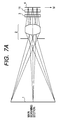
- Figs. 7A and 7B are respectively a plan view (main scanning section) and a side view (sub scanning section) of principal part of an optical system according to the first embodiment of a color image reading apparatus of the present invention.
- the sub scanning section includes an optical axis and is perpendicular to the main scanning section.
- a color image is formed on an original surface 1 as an object to be sensed.
- An imaging optical system 2 images a light beam based on the color image on the surface of a light-receiving means (monolithic 3-line sensor) via a transmission type linear blazed diffraction grating (to be described below).
- a color-separation means 3 comprises a transmission type linear blazed diffraction grating, and separates by transmission and diffraction an incoming light beam into predetermined color light beams, e.g., R (red), G (green), and B (blue), three primary color light beams in a direction (sub scanning direction) perpendicular to the arrangement direction (main scanning direction) of pixels on the line sensor.
- B color light is obtained by -1st-order diffracted light 5, R color light by 0-order diffracted light 6, and G color light by +1st-order diffracted light 7.
- a light-receiving means 4 comprises a so-called monolithic 3-line sensor (to be also referred to as a "3-line sensor” hereinafter) on which three parallel line sensors (CCDs) 8, 9, and 10 are mounted on a single substrate surface to be spaced by equal spacings in the sub scanning direction.
- One pixel has a size of 8 ⁇ m ⁇ 8 ⁇ m, and adjacent sensors are spaced by a spacing corresponding to eight lines.
- a correction means 11 comprises a plane-parallel glass which consists of S-TIH11 (tradename: available from OHARA Corp.) has a tilt with respect to the optical axis of the imaging optical system 2.
- the correction means 11 corrects different imaging positions (focusing positions) in the sub scanning direction produced due to different wavelengths of diffracted light beams by changing (shifting) the optical paths of the color light beams using different refractive indices caused by different wavelengths (colors), so that spacings S 1 and S 2 between adjacent ones of a plurality of color light beams color-separated in the sub scanning direction become equal to each other on the surface of the 3-line sensor 4.
- the color image on the original surface 1 is line-scanned in the sub scanning direction by a scanning means comprising a mirror and the like (not shown), and a light beam coming from the color image illuminated by an illumination light source (not shown) is focused by the imaging optical system 2.
- the focused light beam is color-separated into three color light beams (R, G, and B) via the transmission type linear blazed diffraction grating 3, and color images are then formed on the surfaces of the corresponding line sensors 8, 9, and 10.
- the diffracted light beams of the respective orders color-separated by the linear blazed diffraction grating 3 are corrected by passing them through the plane-parallel glass 11 using different refractive indices (dispersion) of the color light beams produced upon transmitting through the plane-parallel glass 11, so that the spacings S 1 and S 2 between adjacent color beams color-separated in the sub-scanning direction become equal to each other on the surface of the 3-line sensor 4.
- the 3-line sensor digitally reads color images based on these color light beams.
- the line sensors 8, 9, and 10 extend in the main scanning direction agreeing with a direction M in Fig. 7A.
- the transmission type linear blazed diffraction grating serving as the color-separation means separates an incoming light beam mainly into three directions by transmission and diffraction, as disclosed in Applied Optics, Vol. 17, No. 15, pp. 2273 - 2279 (August 1, 1978).
- the transmission type linear blazed diffraction grating separates a light beam, which enters the grating, and transmitted and diffracted, into three directions, i.e., the -1st-order diffracted light 5, 0-order diffracted light 6, and +1st-order diffracted light 7, and images them on the surface of the 3-line sensor 4 as light beams of focused spherical waves by the imaging optical system 2.
- B color light is obtained by the -1st-order diffracted light 5, R color light by the 0-order diffracted light 6, and G color light by the +1st-order diffracted light 7.
- Figs. 8A and 8B are explanatory views showing the relationship of the shift amounts of the respective wavelengths due to different refractive indices (dispersion) caused by different wavelengths (colors). Either when the plane-parallel glass 11 is obliquely disposed with respect to the optical axis, as shown in Fig. 8A, or when a prism 12 is used, as shown in Fig. 8B, a B light ray having the largest refractive index has the largest shift amount, and then G and R light rays come next.
- Figs. 9A, 9B, and 9C are explanatory views showing the relationship between the orders of light rays separated by the blazed diffraction grating, and the wavelengths, and basically, only three patterns illustrated in these figures are available.
- Type A shown in Fig. 9A uses a G light ray (G color light) as 0-order diffracted light, an R light ray (R color light) as 1st-order diffracted light, and a B light ray (B color light) as -1st-order diffracted light, and the diffraction angle of the R light ray having a longer wavelength is larger than that of the B light ray, thus causing asymmetry.
- the asymmetry is corrected by shifting light rays using different refractive indices (dispersion) caused by different wavelength.
- Type B show in Fig. 9B uses an R light ray (R color light) as 0-order diffracted light, a G light ray (G color light) as 1st-order diffracted light, and a B light ray (B color light) as -1st-order diffracted light, and the diffraction angle of the G light ray having a longer wavelength is larger than that of the B light ray, thus causing asymmetry.
- R color light R color light
- G color light G color light
- B color light B color light
- B color light is obtained by the -1st-order diffracted light 5
- R color light is obtained by the 0-order diffracted light 6
- G color light is obtained by the +1st-order diffracted light 7.
- a tilt angle ⁇ the plane-parallel glass 11 inserted in the optical path between the blazed diffraction grating and 3-line sensor 4 makes with the optical axis is set to be 8.32°
- a thickness d is set to be 5 mm
- a grating pitch P of the blazed diffraction grating 3 is set to be 263.90 ⁇ m.
- the simple 3-line sensor 4 can read color image information with high precision by a simple arrangement without requiring high-precision adjustment.
- the tilt angle ⁇ the plane-parallel glass 11 makes with the optical axis is preferably set to fall within the range from 1° to 40°.
- the thickness d of the plane-parallel glass 11 is preferably set to fall within the range from 1 mm to 25 mm.
- B color light is obtained by the -1st-order diffracted light 5
- R color light is obtained by the 0-order diffracted light 6
- G color light is obtained by the +1st-order diffracted light 7.
- R color light may be obtained by the -1st-order diffracted light 5
- B color light by the 0-order diffracted light 6, and G color light by the +1st-order diffracted light 7.
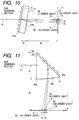
- Fig. 10 is a sectional view of principal part in the sub scanning direction of the second embodiment of the present invention.
- the same reference numerals in Fig. 10 denote the same parts as in Figs. 7A and 7B.
- the difference from the first embodiment described above is that a transmission type blazed diffraction grating and plane-parallel glass are integrated, and are obliquely disposed with respect to the optical axis.
- Other arrangements and optical effects are substantially the same as those in the first embodiment, thus obtaining the same effect.
- an optical member 41 is formed by integrating a transmission type blazed diffraction grating 3 and plane-parallel glass 11, and is disposed to make a predetermined angle with the optical axis of an imaging optical system (not shown).
- B color light is obtained by -1st-order diffracted light 5, R color light by 0-order diffracted light 6, and G color light by +1st-order diffracted light 7, as in the first embodiment described above.
- a grating pitch P of the blazed diffraction grating 3 is set to be 226.26 ⁇ m
- a thickness d 1 of the plane-parallel glass 11 consisting of S-TIH11 (tradename) is set to be 5 mm
- a distance d 2 from an exit surface 41b where 0-order diffracted light (R color light) exits the plane-parallel glass 11 to the surface of a 3-line sensor 4 is set to be 25 mm.
- the optical member 41 obtained by integrating the transmission type blazed diffraction grating 3 and plane-parallel glass 11 is inserted in the optical path to make a predetermined angle with the optical axis of the imaging optical system, the number of components can be reduced, and the simple 3-line sensor 4 can read color image information with high precision by a simple arrangement without requiring high-precision adjustment.
- Fig. 11 is a sectional view of principal part in the sub scanning direction of the third embodiment of the present invention.
- the same reference numerals in Fig. 11 denote the same parts as in Figs. 7A and 7B.
- the difference from the first embodiment described above is that a reflection type blazed diffraction grating is used as a color-separation means, a prism is used as a correction means, and the reflection type blazed diffraction grating and prism are integrated.
- Other arrangements and optical effects are substantially the same as those in the first embodiment, thus obtaining the same effect.
- an optical member 51 is obtained by integrating a reflection type blazed diffraction grating 53 and a prism 52 consisting of S-TIH11 (tradename).
- B color light is obtained by -1st-order diffracted light 5, R color light by 0-order diffracted light 6, and G color light by +1st-order diffracted light 7, as in the first embodiment described above.
- the optical member 51 obtained by integrating the blazed diffraction grating 53 and prism 52 is inserted in the optical path.
- a grating pitch P of the blazed diffraction grating 53 is set to be 314.82 ⁇ m
- a distance d 3 from a diffraction surface (reflection surface) 52b where a chief ray A of a light beam coming from the imaging optical system is reflected and diffracted by the blazed diffraction grating to the exit surface 52c where 0-order diffracted light (R color light) exits the prism 52 is set to be 6 mm
- a distance d 4 from that exit surface 52c to the surface of a 3-line sensor 4 is set to be 24 mm.
- the reflection type blazed diffraction grating 53 and prism 52 are integrated, the number of components can be reduced, and the simple 3-line sensor 4 can read color image information with high precision by a simple arrangement without requiring high-precision adjustment.
- the reflection type blazed diffraction grating 53 and prism 52 are integrated.
- the present invention is not limited to such specific arrangement, and these components may be independently arranged.
- the plane-parallel glass or prism is used as the correction means.
- the present invention can use any other optical elements that can change the optical paths of color light beams using different refractive indices caused by different wavelengths, as in the above embodiments.
- a correction means inserted in the optical path between the diffraction grating and light-receiving means corrects different imaging positions caused by different wavelengths of the color light beams (diffracted light beams) color-separated by the diffraction grating using different refractive indices due to different wavelengths (colors) upon transmitting through the correction means, thus making spacings between adjacent light beams color-separated in the sub scanning direction equal to each other on the surface of the surface of the light-receiving means.
- a color image reading apparatus which can digitally read a color image with high precision using three, R, G,
- a plurality of line sensors are arranged on a same substrate and an image of an object is formed on the sensors by an imaging optical system.
- a blazed diffraction grating is disposed in an optical path between the imaging optical system and the sensors so as to color-separate a light beam from the object into a plurality of color light beams.
- a correction element such as a plane-parallel glass, prism or the like is disposed in an optical path between the blazed diffraction grating and the sensors so as to correct different imaging positions on the surfaces of the sensors caused by different wavelengths of the plurality of color light beams color-separated by the blazed diffraction grating.
- respective optical paths of the color light beams are changed utilizing different refractive indices due to different wavelengths upon being transmitted through the correction element so as to make spacing between adjacent color light beams color-separated in a sub scanning direction equal to each other on the surfaces of the sensors.
Landscapes
- Engineering & Computer Science (AREA)
- Multimedia (AREA)
- Signal Processing (AREA)
- Facsimile Scanning Arrangements (AREA)
- Facsimile Heads (AREA)
Applications Claiming Priority (3)
| Application Number | Priority Date | Filing Date | Title |
|---|---|---|---|
| JP8198097 | 1997-03-14 | ||
| JP08198097A JP3432106B2 (ja) | 1997-03-14 | 1997-03-14 | カラー画像読取装置 |
| JP81980/97 | 1997-03-14 |
Publications (2)
| Publication Number | Publication Date |
|---|---|
| EP0865196A2 true EP0865196A2 (fr) | 1998-09-16 |
| EP0865196A3 EP0865196A3 (fr) | 2000-02-23 |
Family
ID=13761641
Family Applications (1)
| Application Number | Title | Priority Date | Filing Date |
|---|---|---|---|
| EP98104613A Withdrawn EP0865196A3 (fr) | 1997-03-14 | 1998-03-13 | Appareil de lecture d'images en couleurs |
Country Status (3)
| Country | Link |
|---|---|
| US (1) | US6064057A (fr) |
| EP (1) | EP0865196A3 (fr) |
| JP (1) | JP3432106B2 (fr) |
Cited By (1)
| Publication number | Priority date | Publication date | Assignee | Title |
|---|---|---|---|---|
| DE10037701C2 (de) * | 1999-08-10 | 2002-11-21 | Hewlett Packard Co | Farbbilderfassungssystem mit Antialiasing |
Families Citing this family (13)
| Publication number | Priority date | Publication date | Assignee | Title |
|---|---|---|---|---|
| US20010026399A1 (en) * | 1998-09-24 | 2001-10-04 | Masaaki Nakabayashi | Diffractive optical element and method of manufacture of the same |
| JP3376351B2 (ja) | 1999-11-29 | 2003-02-10 | キヤノン株式会社 | 光学系及び原稿読取装置 |
| JP2002062417A (ja) | 2000-06-07 | 2002-02-28 | Canon Inc | 回折光学素子、該回折光学素子を有する光学系及び光学機器、回折光学素子の製造方法、回折光学素子製造用の金型 |
| US6731432B1 (en) * | 2000-06-16 | 2004-05-04 | Mem Optical, Inc. | Off-axis diffractive beam shapers and splitters for reducing sensitivity to manufacturing tolerances |
| JP2002014145A (ja) * | 2000-06-29 | 2002-01-18 | Hamamatsu Photonics Kk | 半導体デバイス検査装置及び半導体デバイス検査方法 |
| JP2002156580A (ja) | 2000-09-05 | 2002-05-31 | Canon Inc | 結像素子及び画像読取装置 |
| US7214926B2 (en) * | 2004-11-19 | 2007-05-08 | Micron Technology, Inc. | Imaging systems and methods |
| JP5030517B2 (ja) * | 2006-09-20 | 2012-09-19 | 株式会社リコー | 光走査装置および画像形成装置およびカラー画像形成装置 |
| JP2011049774A (ja) * | 2009-08-26 | 2011-03-10 | Fuji Xerox Co Ltd | 画像読取装置 |
| TW201115183A (en) * | 2009-10-20 | 2011-05-01 | Ind Tech Res Inst | Stereovision system and calculation method for the distance between object and diffractive optical element |
| JP5945338B2 (ja) * | 2012-03-20 | 2016-07-05 | ノキア テクノロジーズ オーユー | イメージング |
| JP2017049555A (ja) * | 2015-09-04 | 2017-03-09 | シャープ株式会社 | 光学装置及びそれを備えた投影装置 |
| JP7729182B2 (ja) * | 2021-10-29 | 2025-08-26 | セイコーエプソン株式会社 | 画像処理方法、及び分光カメラシステム |
Family Cites Families (9)
| Publication number | Priority date | Publication date | Assignee | Title |
|---|---|---|---|---|
| DE2645075C2 (de) * | 1976-10-06 | 1985-06-20 | Philips Patentverwaltung Gmbh, 2000 Hamburg | Optische Anordnung zur Erzeugung von spektral zerlegten Abbildungen |
| JPS6232765A (ja) * | 1985-08-06 | 1987-02-12 | Hitachi Ltd | コピ−装置 |
| JPS6281871A (ja) * | 1985-10-04 | 1987-04-15 | Oki Electric Ind Co Ltd | 画像読み取り装置 |
| JPH03132252A (ja) * | 1989-10-18 | 1991-06-05 | Konica Corp | カラー画像のライン読取り装置 |
| JPH03226067A (ja) * | 1990-01-30 | 1991-10-07 | Canon Inc | カラー画像読取り装置 |
| JPH0611662A (ja) * | 1992-06-25 | 1994-01-21 | Canon Inc | カラー画像読取装置 |
| JPH0818728A (ja) * | 1994-06-24 | 1996-01-19 | Canon Inc | カラー画像読取装置 |
| JPH0846748A (ja) * | 1994-07-27 | 1996-02-16 | Canon Inc | カラー画像読取装置 |
| JP3240870B2 (ja) * | 1995-02-09 | 2001-12-25 | キヤノン株式会社 | カラー画像読取装置 |
-
1997
- 1997-03-14 JP JP08198097A patent/JP3432106B2/ja not_active Expired - Fee Related
-
1998
- 1998-03-13 EP EP98104613A patent/EP0865196A3/fr not_active Withdrawn
- 1998-03-13 US US09/041,692 patent/US6064057A/en not_active Expired - Fee Related
Cited By (2)
| Publication number | Priority date | Publication date | Assignee | Title |
|---|---|---|---|---|
| DE10037701C2 (de) * | 1999-08-10 | 2002-11-21 | Hewlett Packard Co | Farbbilderfassungssystem mit Antialiasing |
| US6650795B1 (en) | 1999-08-10 | 2003-11-18 | Hewlett-Packard Development Company, L.P. | Color image capturing system with antialiazing |
Also Published As
| Publication number | Publication date |
|---|---|
| EP0865196A3 (fr) | 2000-02-23 |
| JP3432106B2 (ja) | 2003-08-04 |
| US6064057A (en) | 2000-05-16 |
| JPH10257276A (ja) | 1998-09-25 |
Similar Documents
| Publication | Publication Date | Title |
|---|---|---|
| JP3604844B2 (ja) | カラー画像読取装置 | |
| US6064057A (en) | Color image reading apparatus | |
| EP0383307A2 (fr) | Appareil de lecture d'image | |
| US5221835A (en) | Image reading apparatus having a reflective blazed diffraction grating with varied pitch | |
| EP0457281B1 (fr) | Lecteur d'image | |
| US6028705A (en) | Image reading apparatus with reflection type blazed diffraction grating for color separation | |
| EP0731598B1 (fr) | Lecteur pour les images en couleurs | |
| JPH02214370A (ja) | カラー画像読取り装置 | |
| US6738164B1 (en) | Color image reading apparatus | |
| US6930807B1 (en) | Color image reading apparatus | |
| JPH0563909A (ja) | カラー画像読取装置 | |
| JPH0553080A (ja) | カラー画像読取装置 | |
| JP3559658B2 (ja) | カラー画像読取装置 | |
| JPH0870371A (ja) | カラー画像読取装置 | |
| JPH0818728A (ja) | カラー画像読取装置 | |
| JPH04361471A (ja) | カラー画像読取装置 | |
| JP2001111774A (ja) | カラー画像読取装置 | |
| JPH1079834A (ja) | カラー画像読取装置 | |
| JP2002209056A (ja) | カラー画像読み取り装置 | |
| JP2001189829A (ja) | カラー画像読取装置 | |
| JPH04369613A (ja) | カラー画像読取装置 | |
| JP2001127960A (ja) | 画像読取装置 | |
| JPH11220579A (ja) | カラー画像読取装置 | |
| JPH10107952A (ja) | カラー画像読取装置 | |
| JPH06326833A (ja) | カラー画像読取装置 |
Legal Events
| Date | Code | Title | Description |
|---|---|---|---|
| PUAI | Public reference made under article 153(3) epc to a published international application that has entered the european phase |
Free format text: ORIGINAL CODE: 0009012 |
|
| AK | Designated contracting states |
Kind code of ref document: A2 Designated state(s): DE FR GB IT NL |
|
| AX | Request for extension of the european patent |
Free format text: AL;LT;LV;MK;RO;SI |
|
| PUAL | Search report despatched |
Free format text: ORIGINAL CODE: 0009013 |
|
| AK | Designated contracting states |
Kind code of ref document: A3 Designated state(s): AT BE CH DE DK ES FI FR GB GR IE IT LI LU MC NL PT SE |
|
| AX | Request for extension of the european patent |
Free format text: AL;LT;LV;MK;RO;SI |
|
| 17P | Request for examination filed |
Effective date: 20000706 |
|
| AKX | Designation fees paid |
Free format text: DE FR GB IT NL |
|
| 17Q | First examination report despatched |
Effective date: 20050204 |
|
| STAA | Information on the status of an ep patent application or granted ep patent |
Free format text: STATUS: THE APPLICATION HAS BEEN WITHDRAWN |
|
| 18W | Application withdrawn |
Effective date: 20091214 |