EP0865208A2 - Dispositif de codage d'images et méthode associée - Google Patents
Dispositif de codage d'images et méthode associée Download PDFInfo
- Publication number
- EP0865208A2 EP0865208A2 EP98301766A EP98301766A EP0865208A2 EP 0865208 A2 EP0865208 A2 EP 0865208A2 EP 98301766 A EP98301766 A EP 98301766A EP 98301766 A EP98301766 A EP 98301766A EP 0865208 A2 EP0865208 A2 EP 0865208A2
- Authority
- EP
- European Patent Office
- Prior art keywords
- coding
- image
- image data
- picture
- circuit
- Prior art date
- Legal status (The legal status is an assumption and is not a legal conclusion. Google has not performed a legal analysis and makes no representation as to the accuracy of the status listed.)
- Withdrawn
Links
- 238000000034 method Methods 0.000 title claims abstract description 30
- 230000008569 process Effects 0.000 claims abstract description 17
- 230000008859 change Effects 0.000 claims abstract description 7
- 238000013139 quantization Methods 0.000 claims description 31
- 230000003287 optical effect Effects 0.000 claims description 7
- 238000012545 processing Methods 0.000 claims description 7
- 238000010586 diagram Methods 0.000 description 9
- 230000015572 biosynthetic process Effects 0.000 description 8
- 238000010276 construction Methods 0.000 description 7
- 239000004065 semiconductor Substances 0.000 description 7
- 230000006835 compression Effects 0.000 description 6
- 238000007906 compression Methods 0.000 description 6
- 238000001514 detection method Methods 0.000 description 6
- 101000969688 Homo sapiens Macrophage-expressed gene 1 protein Proteins 0.000 description 3
- 102100021285 Macrophage-expressed gene 1 protein Human genes 0.000 description 3
- 238000009825 accumulation Methods 0.000 description 2
- 238000012937 correction Methods 0.000 description 2
- 230000001131 transforming effect Effects 0.000 description 2
- 230000003044 adaptive effect Effects 0.000 description 1
- 230000004075 alteration Effects 0.000 description 1
- 238000013459 approach Methods 0.000 description 1
- 239000002131 composite material Substances 0.000 description 1
- 230000006866 deterioration Effects 0.000 description 1
- 230000002542 deteriorative effect Effects 0.000 description 1
- 230000000694 effects Effects 0.000 description 1
- 239000004973 liquid crystal related substance Substances 0.000 description 1
- 230000004048 modification Effects 0.000 description 1
- 238000012986 modification Methods 0.000 description 1
- 238000012544 monitoring process Methods 0.000 description 1
- 230000009467 reduction Effects 0.000 description 1
- 230000009466 transformation Effects 0.000 description 1
- 238000009966 trimming Methods 0.000 description 1
Images


Classifications
-
- H—ELECTRICITY
- H04—ELECTRIC COMMUNICATION TECHNIQUE
- H04N—PICTORIAL COMMUNICATION, e.g. TELEVISION
- H04N5/00—Details of television systems
- H04N5/76—Television signal recording
- H04N5/765—Interface circuits between an apparatus for recording and another apparatus
- H04N5/77—Interface circuits between an apparatus for recording and another apparatus between a recording apparatus and a television camera
- H04N5/772—Interface circuits between an apparatus for recording and another apparatus between a recording apparatus and a television camera the recording apparatus and the television camera being placed in the same enclosure
-
- H—ELECTRICITY
- H04—ELECTRIC COMMUNICATION TECHNIQUE
- H04N—PICTORIAL COMMUNICATION, e.g. TELEVISION
- H04N19/00—Methods or arrangements for coding, decoding, compressing or decompressing digital video signals
- H04N19/10—Methods or arrangements for coding, decoding, compressing or decompressing digital video signals using adaptive coding
- H04N19/102—Methods or arrangements for coding, decoding, compressing or decompressing digital video signals using adaptive coding characterised by the element, parameter or selection affected or controlled by the adaptive coding
- H04N19/103—Selection of coding mode or of prediction mode
- H04N19/105—Selection of the reference unit for prediction within a chosen coding or prediction mode, e.g. adaptive choice of position and number of pixels used for prediction
-
- H—ELECTRICITY
- H04—ELECTRIC COMMUNICATION TECHNIQUE
- H04N—PICTORIAL COMMUNICATION, e.g. TELEVISION
- H04N19/00—Methods or arrangements for coding, decoding, compressing or decompressing digital video signals
- H04N19/10—Methods or arrangements for coding, decoding, compressing or decompressing digital video signals using adaptive coding
- H04N19/102—Methods or arrangements for coding, decoding, compressing or decompressing digital video signals using adaptive coding characterised by the element, parameter or selection affected or controlled by the adaptive coding
- H04N19/124—Quantisation
-
- H—ELECTRICITY
- H04—ELECTRIC COMMUNICATION TECHNIQUE
- H04N—PICTORIAL COMMUNICATION, e.g. TELEVISION
- H04N19/00—Methods or arrangements for coding, decoding, compressing or decompressing digital video signals
- H04N19/10—Methods or arrangements for coding, decoding, compressing or decompressing digital video signals using adaptive coding
- H04N19/134—Methods or arrangements for coding, decoding, compressing or decompressing digital video signals using adaptive coding characterised by the element, parameter or criterion affecting or controlling the adaptive coding
- H04N19/162—User input
-
- H—ELECTRICITY
- H04—ELECTRIC COMMUNICATION TECHNIQUE
- H04N—PICTORIAL COMMUNICATION, e.g. TELEVISION
- H04N19/00—Methods or arrangements for coding, decoding, compressing or decompressing digital video signals
- H04N19/10—Methods or arrangements for coding, decoding, compressing or decompressing digital video signals using adaptive coding
- H04N19/169—Methods or arrangements for coding, decoding, compressing or decompressing digital video signals using adaptive coding characterised by the coding unit, i.e. the structural portion or semantic portion of the video signal being the object or the subject of the adaptive coding
- H04N19/17—Methods or arrangements for coding, decoding, compressing or decompressing digital video signals using adaptive coding characterised by the coding unit, i.e. the structural portion or semantic portion of the video signal being the object or the subject of the adaptive coding the unit being an image region, e.g. an object
- H04N19/172—Methods or arrangements for coding, decoding, compressing or decompressing digital video signals using adaptive coding characterised by the coding unit, i.e. the structural portion or semantic portion of the video signal being the object or the subject of the adaptive coding the unit being an image region, e.g. an object the region being a picture, frame or field
-
- H—ELECTRICITY
- H04—ELECTRIC COMMUNICATION TECHNIQUE
- H04N—PICTORIAL COMMUNICATION, e.g. TELEVISION
- H04N19/00—Methods or arrangements for coding, decoding, compressing or decompressing digital video signals
- H04N19/10—Methods or arrangements for coding, decoding, compressing or decompressing digital video signals using adaptive coding
- H04N19/169—Methods or arrangements for coding, decoding, compressing or decompressing digital video signals using adaptive coding characterised by the coding unit, i.e. the structural portion or semantic portion of the video signal being the object or the subject of the adaptive coding
- H04N19/17—Methods or arrangements for coding, decoding, compressing or decompressing digital video signals using adaptive coding characterised by the coding unit, i.e. the structural portion or semantic portion of the video signal being the object or the subject of the adaptive coding the unit being an image region, e.g. an object
- H04N19/176—Methods or arrangements for coding, decoding, compressing or decompressing digital video signals using adaptive coding characterised by the coding unit, i.e. the structural portion or semantic portion of the video signal being the object or the subject of the adaptive coding the unit being an image region, e.g. an object the region being a block, e.g. a macroblock
-
- H—ELECTRICITY
- H04—ELECTRIC COMMUNICATION TECHNIQUE
- H04N—PICTORIAL COMMUNICATION, e.g. TELEVISION
- H04N19/00—Methods or arrangements for coding, decoding, compressing or decompressing digital video signals
- H04N19/60—Methods or arrangements for coding, decoding, compressing or decompressing digital video signals using transform coding
- H04N19/61—Methods or arrangements for coding, decoding, compressing or decompressing digital video signals using transform coding in combination with predictive coding
-
- H—ELECTRICITY
- H04—ELECTRIC COMMUNICATION TECHNIQUE
- H04N—PICTORIAL COMMUNICATION, e.g. TELEVISION
- H04N23/00—Cameras or camera modules comprising electronic image sensors; Control thereof
- H04N23/60—Control of cameras or camera modules
-
- H—ELECTRICITY
- H04—ELECTRIC COMMUNICATION TECHNIQUE
- H04N—PICTORIAL COMMUNICATION, e.g. TELEVISION
- H04N19/00—Methods or arrangements for coding, decoding, compressing or decompressing digital video signals
- H04N19/10—Methods or arrangements for coding, decoding, compressing or decompressing digital video signals using adaptive coding
- H04N19/102—Methods or arrangements for coding, decoding, compressing or decompressing digital video signals using adaptive coding characterised by the element, parameter or selection affected or controlled by the adaptive coding
- H04N19/103—Selection of coding mode or of prediction mode
- H04N19/107—Selection of coding mode or of prediction mode between spatial and temporal predictive coding, e.g. picture refresh
-
- H—ELECTRICITY
- H04—ELECTRIC COMMUNICATION TECHNIQUE
- H04N—PICTORIAL COMMUNICATION, e.g. TELEVISION
- H04N19/00—Methods or arrangements for coding, decoding, compressing or decompressing digital video signals
- H04N19/10—Methods or arrangements for coding, decoding, compressing or decompressing digital video signals using adaptive coding
- H04N19/134—Methods or arrangements for coding, decoding, compressing or decompressing digital video signals using adaptive coding characterised by the element, parameter or criterion affecting or controlling the adaptive coding
- H04N19/146—Data rate or code amount at the encoder output
- H04N19/152—Data rate or code amount at the encoder output by measuring the fullness of the transmission buffer
-
- H—ELECTRICITY
- H04—ELECTRIC COMMUNICATION TECHNIQUE
- H04N—PICTORIAL COMMUNICATION, e.g. TELEVISION
- H04N5/00—Details of television systems
- H04N5/76—Television signal recording
- H04N5/907—Television signal recording using static stores, e.g. storage tubes or semiconductor memories
-
- H—ELECTRICITY
- H04—ELECTRIC COMMUNICATION TECHNIQUE
- H04N—PICTORIAL COMMUNICATION, e.g. TELEVISION
- H04N9/00—Details of colour television systems
- H04N9/79—Processing of colour television signals in connection with recording
- H04N9/80—Transformation of the television signal for recording, e.g. modulation, frequency changing; Inverse transformation for playback
- H04N9/804—Transformation of the television signal for recording, e.g. modulation, frequency changing; Inverse transformation for playback involving pulse code modulation of the colour picture signal components
- H04N9/8042—Transformation of the television signal for recording, e.g. modulation, frequency changing; Inverse transformation for playback involving pulse code modulation of the colour picture signal components involving data reduction
Definitions
- the invention relates to image coding apparatus and method for efficiently coding image data.
- An MPEG (Moving Picture Experts Group) system is widely known as a system for highly efficiently compressing and coding motion image data.
- the MPEG system is a coding system in which a discrete cosine transformation (DCT), an adaptive quantization, and a variable length coding are used as fundamental techniques and an interframe (or interfield) predictive coding with motion compensation based on a frame (or field) correlation is adaptively combined.
- DCT discrete cosine transformation
- an adaptive quantization an adaptive quantization
- variable length coding used as fundamental techniques
- an interframe (or interfield) predictive coding with motion compensation based on a frame (or field) correlation is adaptively combined.
- an I picture in which each frame is coded in a picture plane, a P picture which is interframe (or interfield) motion compensation predictive coded from the I picture that is preceding with respect to the time, and a B picture which is interframe (or interfield) motion compensation predictive coded from both of the preceding I picture (or P picture) and the subsequent I picture (or P picture) are arranged in accordance with a proper order, thereby accomplishing a high compression ratio.
- a recent image coding system has a construction which can be also called a set of various coding techniques.
- various coding methods there are advantages and disadvantages depending on a photographing situation or an object.
- which coding method is used is proper can be discriminated for the first time by analyzing an image signal inputted to a compression processing circuit.
- the MPEG system is what is called a collective method of those composite coding methods.
- a camera integrated type recording and reproducing apparatus using the MPEG system has already been manufactured as an article of commerce.
- a compression ratio is higher than that of a compression coding system of a conventional digital VCR for industrial use, a longer time recording can be performed with a smaller recording capacity, and it is suitable for a portable camera apparatus.
- the MPEG system is not suitable to form a predictive coding image for a period of time of the camera operation such as zoom-in (enlargement), zoom-out (reduction), or the like. That is, since it is difficult to obtain a correlation between the picture planes during the zooming operation, a large amount of unnecessary data is generated due to prediction errors. Not only a coding efficiency deteriorates but also a picture quality deteriorates.
- an image coding apparatus comprising: input means for inputting image data; image changing means for giving a continuous change to the image data; coding means for coding the image data; and control means for controlling coding conditions of the coding means in accordance with an output of the changing means.
- an image coding method comprising: an image changing step of giving a continuous change to input image data; a coding step of coding the image data; and a control step of controlling a coding condition of the coding means in accordance with a process in the changing step.
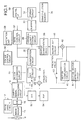
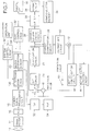
- Fig. 1 is a block diagram showing a construction of a digital video camera of the first embodiment according to the invention.
- Reference numeral 10 denotes a photographing lens constructed by a plurality of lens groups; 12 a zoom drive circuit for zooming the photographing lens 10; 14 an image pickup for converting an optical image obtained by the photographing lens 10 into an electric signal; 16 an A/D converter for converting an analog output of the image pickup 14 into a digital signal; and 18 a camera signal processing circuit for performing well-known camera signal processes such as gamma correction, color balance correction, and, the like to output data of the A/D converter 16.
- Reference numeral 22 denotes a switch for selecting image data (a contact) of a block unit from a block formation circuit 20 or a prediction error (b contact) between the actual picture plane and a predictive picture plane; 24 a DCT circuit for discrete cosine transforming an output of the switch 22 and outputting DCT coefficient data; 26 a quantization circuit for quantizing the DCT coefficient data outputted from the DCT circuit 24 by a designated quantization step size; 28 a variable length coding circuit for variable length coding an output of the quantization circuit 26; 30 a buffer for storing an output of the variable length coding circuit 28; and 32 a rate control circuit for controlling a quantization step of the quantization circuit 26 in accordance with a data amount in the buffer 30.
- Reference numeral 34 denotes a format circuit for converting data from the buffer 30 into a recording format in a semiconductor memory 36.
- Reference numeral 38 denotes an inverse quantization circuit for inversely quantizing the output of the quantization circuit 26; 40 an inverse DCT circuit for inversely discrete cosine transforming an output of the inverse quantization circuit 38.
- Reference numeral 42 denotes an adder for adding a predictive value to an output of the inverse DCT circuit 40 and outputting a resultant value in an inter-picture plane predictive coding mode (inter-coding mode) [P picture (forward prediction) and B picture (two-way prediction)] or for outputting the output of the inverse DCT circuit 40 as it is in an intra-picture plane coding mode (intra-coding mode) (I picture).
- inter-coding mode inter-coding mode
- I picture intra-picture plane coding mode
- Reference numeral 44 denotes a motion vector detection circuit for comparing an output of the adder 42 with image data of the present picture plane from the block formation circuit 20 and detecting a motion on a block unit basis of a predetermined size.
- Reference numeral 46 denotes a motion compensation circuit for moving image data of a predictive picture plane in the picture plane so as to set off the motion in accordance with a motion vector detected by the motion vector detection circuit 44.
- An output of the motion compensation circuit 46 is supplied as a prediction value to the adder 42 through a subtractor 48 and a switch 50.
- the subtractor 48 calculates a difference between the output of the block formation circuit 20 and the output (prediction value) of the motion compensation circuit 46, namely, a prediction error and supplies to a b contact of the switch 22.
- Reference numeral 52 denotes a D/A converter for converting the digital output of the camera signal processing circuit 18 into an analog signal; and 54 an electronic view finder for displaying a video image according to an output signal of the D/A converter 52.
- the user can observe the video image during the photographing or during the photographing preparation.
- Reference numeral 56 denotes a system control circuit for controlling the whole apparatus; 58 an operation unit comprising operation keys for the user to input various instructions to the system control circuit 56; and 59 a digital interface (for example, IEEE1394).
- the image pickup 14 converts the optical image obtained by the photographing lens 10 into the electric signal.
- the output signal of the image pickup 14 is converted into the digital signal by the A/D converter 16 and is subjected to well-known camera signal processes by the camera signal processing circuit 18.
- the block formation circuit 20 divides the image data outputted from the camera signal processing circuit 18 into blocks of (8 pixels ⁇ 8 pixels).
- An output of the block formation circuit 20 is supplied to the a contact of the switch 22, subtractor 48, and motion vector detection circuit 44.
- the subtractor 48 calculates a difference (prediction error) between the pixel data from the block formation circuit 20 and the prediction value outputted from the motion compensation circuit 46 and supplies to the b contact of the switch 22.
- the switch 22 is connected to the a contact in the I picture [intra-picture plane coding mode (intra-coding mode)] and is connected to the b contact in the B picture [inter-picture plane coding mode (inter-coding mode)]. Therefore, in the I picture, the output of the block formation circuit 20 is supplied to the DCT circuit 24. In the P picture or the B picture, the output (prediction error) of the subtractor 48 is supplied.
- the DCT circuit 24 discrete cosine (DCT) transforms the data from the switch 22 on a block unit basis and outputs DCT coefficient data to the quantization circuit 26.
- the quantization circuit 26 quantizes the DCT coefficient data from the DCT circuit 24 by a quantization step size designated by the rate control circuit 32.
- the variable length coding circuit 28 variable length codes the output of the quantization circuit 26.
- the rate control circuit 32 monitors a data accumulation amount in the buffer 30 and controls the quantization step size of the quantization circuit 26 so that the data accumulation amount does not overflow.
- the inverse quantization circuit 38 inversely quantizes the output of the quantization circuit 26 by the same quantization step size as that selected in the quantization circuit 26 and outputs a representative value of a DCT coefficient.
- the inverse DCT circuit 40 inversely discrete cosine transforms the output of the inverse quantization circuit 38.
- the switch 50 is opened in the intra-coding mode (I picture) and is closed in the inter-coding mode (P picture or B picture). Therefore, the adder 42 adds a prediction value (output of the motion compensation circuit 46) to the output of the inverse DCT circuit 40 in the inter-coding mode and outputs the output of the inverse DCT circuit 40 as it is in the intra-coding mode.
- the motion vector detection circuit 44 compares the pixel data of the present frame from the block formation circuit 20 with the pixel data of the prediction frame from the adder 42, thereby detecting a motion of the image.
- the motion compensation circuit 46 moves the pixel data of the prediction frame from the adder 42 in the picture plane so as to set off the motion in accordance with the motion vector detected by the motion vector detection circuit 42.
- the output of the motion compensation circuit 46 is supplied as a prediction value to the adder 42 through the subtractor 48 and switch 50.
- the output of the variable length coding circuit 28 is rate adjusted by the buffer 30 and is supplied to the format circuit 34.
- the format circuit 34 formats the data from the buffer 30 into a recording format of the semiconductor memory 36 and supplies the resultant data to the semiconductor memory 36. Specifically speaking, the format circuit 34 adds various headers such as slice header, sequence header, and the like in the data structure of MPEG1 to the coding data and forms MPEG image data corresponding to the MPEG1 system and writes into the semiconductor memory 36.
- the output of the camera signal processing circuit 18 is converted into the analog signal by the D/A converter 52 and is supplied to the electronic view finder 54.
- the user can monitor the image during the photographing preparation or the image to be recorded.
- the coding data outputted from the buffer 30 can be outputted to an external apparatus via the digital interface 59.
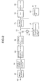
- Fig. 2 shows a schematic constructional block diagram of the reproducing system for reproducing the image recorded in the semiconductor memory 36 as mentioned above.
- Reference numeral 60 denotes an input terminal of the coding data read out from the semiconductor memory 36; 62 an input buffer; 64 a variable length decoding circuit; 66 an inverse quantization circuit; 68 an inverse DCT circuit; 70 an adder for adding the prediction value to an output of the inverse DCT circuit 68; 72 a switch for selecting the output (a contact) of the inverse DCT circuit 68 in case of the I picture and selecting an output (b contact) of the adder 70 in case of the P picture or the B picture on the basis of identification information of the coding system; 74 a motion compensation circuit for outputting a prediction value which is motion compensated from an output of the switch 72; 76 an output buffer for storing the output of the switch 72; 78 a D/A converter for converting an output of the output buffer 76 into an analog signal; 80 a monitor for displaying a video image from an output
- the coding data inputted to the input terminal 60 is supplied to the variable length decoding circuit 64 through the input buffer 62 and is variable length decoded.
- An output of the variable length decoding circuit 64 is inversely quantized by the inverse quantization circuit 66 and is inversely DCT transformed by the inverse DCT circuit 68.
- An output of the inverse DCT circuit 68 of the I picture is transferred as it is to the output buffer 76 and motion compensation circuit 74 through the switch 72.
- An output of the inverse DCT circuit 68 of the P picture or the B picture is a differential signal between the picked-up frame and the prediction frame.
- a resultant value is sent to the output buffer 76 and motion compensation circuit 74 through the switch 72.
- the motion compensation circuit 74 calculates the prediction value to be added by the adder 70 from the data (reconstructed image data) from the switch 72 and supplies to the adder 70.
- the output buffer 76 converts the image data according to the block order for compression coding in accordance with the raster order and generates the converted data.
- the output of the output buffer 76 is supplied to the D/A converter 78 and digital interface 82.
- the D/A converter 78 converts the output of the output buffer 76 into the analog signal and supplies to the monitor 80 such as a liquid crystal display apparatus or the like. Thus, a reproduction image is displayed.
- the digital interface 82 outputs the data from the buffer 76 to the digital output terminal 84 in a predetermined format.
- the operator when an object image is optically zoomed in/out (enlarged/reduced), the operator operates a zoom lever of the operation unit 58 while monitoring the image.
- the system control circuit 56 moves a lens for zooming of the photographing lens 10 in the optical axis direction through the zoom drive circuit 12, thereby changing to a desired angle of view.
- the system control circuit 56 also forcedly connects the switch 22 to the contact for a zooming period of time.
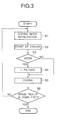
- a coding mode control during the zooming operation will now be described in detail with reference to Fig. 3.
- the camera integrated type recording and reproducing apparatus of the embodiment is set into a photographing mode and the photographing operation is started.
- a parameter which is used for coding is initialized (step S1).
- any one of the I picture, P picture, and B picture can be used.
- the recording of the photographed image namely, a coding process of the photographed image is started (S2).
- the presence or absence of the zooming operation is always monitored (S3).
- the apparatus is fixed to a coding mode of only the I picture (S4) and the photographed image is coded (S5).
- the photographed image is coded in a coding mode using the I picture, P picture, and B picture in the ordinary manner (S6).
- step S1 The processes after step S1 are repeated (S6) until the operation to finish the photographing (recording) is performed.
- the photographing is finished by the photographing finishing operation.
- the embodiment is suitable, particularly, for a case where the zoom can be controlled at an extremely high speed.
- the invention can be obviously applied to an electronic zoom besides the optical zoom.
- a magnetic tape, a magnetic disk, or a magnetooptic disk can be also used as a recording medium.
- the image compressing system is not limited to the MPEG1 system but can also use an MPEG2 system, or further, another coding system using both of the inter-picture plane coding and the intra-picture plane coding.
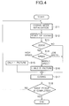
- Fig. 4 shows a flowchart for the coding mode selection according to a modification.
- the parameter which is used for coding is initialized (S11). At this stage, any one of the I picture, P picture, and B picture can be used.
- the recording of the photographed image namely, a coding process of the photographed image is started (S12).
- the presence or absence of the zooming operation is always monitored (S13).
- the zooming operation zoom-in or zoom-out
- the zooming speed is examined (S14).
- the apparatus is fixed to the coding mode of only the I picture (S15) and the photographed image is coded (S17).
- the zooming speed is middle, the apparatus is set into the coding mode using the I picture and the P picture (S16).
- the photographed image is coded (S17).
- the photographed image is coded in the coding mode using the I picture, P picture, and B picture in the ordinary manner (S17).
- step S11 are repeated (S18) until the operation to finish the photographing (recording) is performed.
- the photographing is finished by the photographing finishing operation.
- Fig. 5 is a block diagram showing a construction of a digital video camera of the second embodiment according to the invention.
- the same portions as those in Fig. 1 are designated by the same reference numerals and their descriptions are omitted.
- a quantization step size is further controlled.
- the embodiment is made by paying attention to an idea such that when the zooming operation is being performed, the photographer pays an attention to an object existing at a far end of the zoom and he ought to obviously desire that a person who observes the video image also pays an attention to such a target portion. That is, since the center of the picture plane is a focal point of the zoom, a quantization step size of the image data near the center of the picture plane is set to be smaller than that of the other portion, thereby allocating a larger code amount to such image data. In other words, a picture quality of the image in the center portion. This also provides an effect of preventing a raid increase in code amount due to the change in coding mode.
- a system control circuit 56' supplies zoom operation information (also including information of the zooming speed and the like) showing the contents of the zooming operation to a rate control circuit 32'.
- the rate control circuit 32' controls the quantization step size which is used for a quantizing process in consideration of the zooming operation information.
- Figs. 6A and 6B are diagrams for explaining the relation among the quantization step sizes at the time of the zooming operation.
- one picture plane is divided into three areas concentrically from the center of the picture plane and the quantization step size is reduced as the position approaches the center of the picture plane.
- one picture plane has been divided into three areas, it can be also further finely divided into the areas.
- Fig. 6A shows a case of the middle zooming speed.
- Fig. 6B shows a case of the high zooming speed.
- the quantization step is executed by an ordinary rate control process.
- the invention can be also applied to a case of electrically performing the zooming process (electronic zoom) instead of the optical method.
- Such a constructional example is shown in Fig. 7. It is sufficient that the system control circuit 56' controls an electronic zoom circuit 100 in accordance with the operation of the zoom lever of the operation unit 58.
Landscapes
- Engineering & Computer Science (AREA)
- Multimedia (AREA)
- Signal Processing (AREA)
- Compression Or Coding Systems Of Tv Signals (AREA)
- Compression, Expansion, Code Conversion, And Decoders (AREA)
- Television Signal Processing For Recording (AREA)
Applications Claiming Priority (3)
| Application Number | Priority Date | Filing Date | Title |
|---|---|---|---|
| JP5597097A JP3592025B2 (ja) | 1997-03-11 | 1997-03-11 | 撮影画像記録装置 |
| JP5597097 | 1997-03-11 | ||
| JP55970/97 | 1997-03-11 |
Publications (2)
| Publication Number | Publication Date |
|---|---|
| EP0865208A2 true EP0865208A2 (fr) | 1998-09-16 |
| EP0865208A3 EP0865208A3 (fr) | 1999-11-03 |
Family
ID=13013941
Family Applications (1)
| Application Number | Title | Priority Date | Filing Date |
|---|---|---|---|
| EP19980301766 Withdrawn EP0865208A3 (fr) | 1997-03-11 | 1998-03-10 | Dispositif de codage d'images et méthode associée |
Country Status (3)
| Country | Link |
|---|---|
| US (2) | US6952448B2 (fr) |
| EP (1) | EP0865208A3 (fr) |
| JP (1) | JP3592025B2 (fr) |
Cited By (5)
| Publication number | Priority date | Publication date | Assignee | Title |
|---|---|---|---|---|
| EP1087620A3 (fr) * | 1999-09-22 | 2004-05-12 | Matsushita Electric Industrial Co., Ltd. | Commutateur et méthode de commutation de trames vidéo, caméra numérique, et système de supervision |
| EP1703739A1 (fr) * | 2005-03-14 | 2006-09-20 | Canon Kabushiki Kaisha | Dispositif et méthode de traitement d'images, programme d'ordinateur et support de stockage pour sélection de formes de block de pixels en fonction d'informations de prise de vue |
| EP1770639A3 (fr) * | 2004-06-17 | 2007-04-11 | Canon Kabushiki Kaisha | Codeur d'images animées |
| US8064521B2 (en) | 2003-12-22 | 2011-11-22 | Canon Kabushiki Kaisha | Motion image coding apparatus, and control method and program of the apparatus |
| EP2667614A4 (fr) * | 2011-01-21 | 2013-11-27 | Panasonic Corp | Dispositif de codage de film cinématographique et procédé de codage de film cinématographique |
Families Citing this family (8)
| Publication number | Priority date | Publication date | Assignee | Title |
|---|---|---|---|---|
| JP4000413B2 (ja) | 1998-11-18 | 2007-10-31 | 富士フイルム株式会社 | 電子カメラ |
| US8861600B2 (en) * | 2004-06-18 | 2014-10-14 | Broadcom Corporation | Method and system for dynamically configurable DCT/IDCT module in a wireless handset |
| JP4411220B2 (ja) | 2005-01-18 | 2010-02-10 | キヤノン株式会社 | 映像信号処理装置、及びその映像信号処理方法 |
| JP2007295370A (ja) * | 2006-04-26 | 2007-11-08 | Sony Corp | 符号化装置および方法、並びにプログラム |
| US8737825B2 (en) | 2009-09-10 | 2014-05-27 | Apple Inc. | Video format for digital video recorder |
| US8554061B2 (en) * | 2009-09-10 | 2013-10-08 | Apple Inc. | Video format for digital video recorder |
| EP4284001A3 (fr) * | 2012-08-15 | 2024-01-17 | Intuitive Surgical Operations, Inc. | Procédés et systèmes d'optimisation de diffusion vidéo en continu |
| JP6086619B2 (ja) | 2015-03-27 | 2017-03-01 | 株式会社日立国際電気 | 符号化装置および符号化方法 |
Family Cites Families (16)
| Publication number | Priority date | Publication date | Assignee | Title |
|---|---|---|---|---|
| US4698672A (en) * | 1986-10-27 | 1987-10-06 | Compression Labs, Inc. | Coding system for reducing redundancy |
| JPH0468989A (ja) | 1990-07-09 | 1992-03-04 | Matsushita Electric Ind Co Ltd | 動き補償フレーム間/フレーム内符号化装置 |
| JPH0813138B2 (ja) | 1990-11-28 | 1996-02-07 | 松下電器産業株式会社 | 画像符号化装置 |
| US5357281A (en) | 1991-11-07 | 1994-10-18 | Canon Kabushiki Kaisha | Image processing apparatus and terminal apparatus |
| JPH05167998A (ja) * | 1991-12-16 | 1993-07-02 | Nippon Telegr & Teleph Corp <Ntt> | 画像の符号化制御処理方法 |
| EP0586218B1 (fr) * | 1992-09-01 | 1998-07-22 | Canon Kabushiki Kaisha | Appareil de traitement d'images |
| US5402171A (en) * | 1992-09-11 | 1995-03-28 | Kabushiki Kaisha Toshiba | Electronic still camera with improved picture resolution by image shifting in a parallelogram arrangement |
| JP3133517B2 (ja) | 1992-10-15 | 2001-02-13 | シャープ株式会社 | 画像領域検出装置、該画像検出装置を用いた画像符号化装置 |
| FR2697393A1 (fr) * | 1992-10-28 | 1994-04-29 | Philips Electronique Lab | Dispositif de codage de signaux numériques représentatifs d'images, et dispositif de décodage correspondant. |
| JP3221785B2 (ja) | 1993-10-07 | 2001-10-22 | 株式会社日立製作所 | 撮像装置 |
| JPH07162853A (ja) | 1993-12-07 | 1995-06-23 | Hitachi Ltd | 撮像装置 |
| KR100213014B1 (ko) * | 1994-03-15 | 1999-08-02 | 윤종용 | 동화상신호의 고능률 부호화를 위한 레이트 콘트롤 장치 |
| JP3382362B2 (ja) | 1994-07-29 | 2003-03-04 | キヤノン株式会社 | 画像信号生成装置 |
| US5550847A (en) * | 1994-10-11 | 1996-08-27 | Motorola, Inc. | Device and method of signal loss recovery for realtime and/or interactive communications |
| US5926209A (en) * | 1995-07-14 | 1999-07-20 | Sensormatic Electronics Corporation | Video camera apparatus with compression system responsive to video camera adjustment |
| US5926224A (en) * | 1995-07-31 | 1999-07-20 | Sony Corporation | Imaging, system, video processing apparatus, encoding apparatus, encoding method, and method of removing random noise |
-
1997
- 1997-03-11 JP JP5597097A patent/JP3592025B2/ja not_active Expired - Fee Related
-
1998
- 1998-03-09 US US09/038,707 patent/US6952448B2/en not_active Expired - Fee Related
- 1998-03-10 EP EP19980301766 patent/EP0865208A3/fr not_active Withdrawn
-
2005
- 2005-07-27 US US11/189,928 patent/US7369611B2/en not_active Expired - Fee Related
Cited By (10)
| Publication number | Priority date | Publication date | Assignee | Title |
|---|---|---|---|---|
| EP1087620A3 (fr) * | 1999-09-22 | 2004-05-12 | Matsushita Electric Industrial Co., Ltd. | Commutateur et méthode de commutation de trames vidéo, caméra numérique, et système de supervision |
| EP2148511A3 (fr) * | 1999-09-22 | 2010-04-28 | Panasonic Corporation | Commutateur et méthode de commutation de trames vidéo, caméra numérique, et système de supervision |
| US8064521B2 (en) | 2003-12-22 | 2011-11-22 | Canon Kabushiki Kaisha | Motion image coding apparatus, and control method and program of the apparatus |
| EP1700481B1 (fr) * | 2003-12-22 | 2012-02-22 | Canon Kabushiki Kaisha | Appareil de codage d'image mobile, et procede de commande et programme de cet appareil |
| EP1770639A3 (fr) * | 2004-06-17 | 2007-04-11 | Canon Kabushiki Kaisha | Codeur d'images animées |
| US8369402B2 (en) | 2004-06-17 | 2013-02-05 | Canon Kabushiki Kaisha | Apparatus and method for prediction modes selection based on image formation |
| EP1703739A1 (fr) * | 2005-03-14 | 2006-09-20 | Canon Kabushiki Kaisha | Dispositif et méthode de traitement d'images, programme d'ordinateur et support de stockage pour sélection de formes de block de pixels en fonction d'informations de prise de vue |
| CN100518322C (zh) * | 2005-03-14 | 2009-07-22 | 佳能株式会社 | 图像处理装置和方法 |
| US7760953B2 (en) | 2005-03-14 | 2010-07-20 | Canon Kabushiki Kaisha | Image processing apparatus and method, computer program, and storage medium with varied block shapes to execute motion detection |
| EP2667614A4 (fr) * | 2011-01-21 | 2013-11-27 | Panasonic Corp | Dispositif de codage de film cinématographique et procédé de codage de film cinématographique |
Also Published As
| Publication number | Publication date |
|---|---|
| EP0865208A3 (fr) | 1999-11-03 |
| US20050259731A1 (en) | 2005-11-24 |
| JP3592025B2 (ja) | 2004-11-24 |
| US20020114390A1 (en) | 2002-08-22 |
| US6952448B2 (en) | 2005-10-04 |
| US7369611B2 (en) | 2008-05-06 |
| JPH10257366A (ja) | 1998-09-25 |
Similar Documents
| Publication | Publication Date | Title |
|---|---|---|
| KR100837992B1 (ko) | 디지털 카메라 및 화상 처리 장치 | |
| US7903162B2 (en) | Electronic camera that display information representative of its selected mode | |
| KR100893419B1 (ko) | 촬상 장치 및 촬상 방법 | |
| JPH06181569A (ja) | 画像符号化及び復号化方法又は装置、及び画像記録媒体 | |
| US7369611B2 (en) | Image coding apparatus and method of the same | |
| US7075985B2 (en) | Methods and systems for efficient video compression by recording various state signals of video cameras | |
| JP3783238B2 (ja) | 撮像システム、画像処理装置、符号化装置、符号化方法及びランダムノイズを除去する方法 | |
| EP0520741A1 (fr) | Compression d'images liée à la correction de tremblotements de caméra | |
| US6205286B1 (en) | Image pickup apparatus having image information compressing function | |
| CN1113632A (zh) | 带有压缩或扩展光图像电视频信号装置的输入和输出光图像的设备 | |
| JP2004180345A (ja) | 撮影画像記録装置 | |
| JP2005300943A (ja) | 情報表示位置制御方法及び装置 | |
| JP2003158661A (ja) | ビデオカメラ | |
| JP2001145011A (ja) | 映像信号符号化装置 | |
| JP3151244B2 (ja) | 画像記録装置 | |
| JPH09186919A (ja) | 撮像装置 | |
| EP0926883B1 (fr) | Procédé et appareil de traitement d'image | |
| JP3384910B2 (ja) | 撮像装置および画像再生装置 | |
| JPH04373369A (ja) | 撮像装置 | |
| JP2006166255A (ja) | 画像符号化装置、撮像装置、画像記録方法、画像記録装置、画像記録媒体及び画像再生装置 | |
| JPH0865565A (ja) | 撮像記録装置 | |
| JPH09307908A (ja) | 符号化制御器 | |
| JPH04238477A (ja) | 画像データ圧縮記憶装置の制御方法 |
Legal Events
| Date | Code | Title | Description |
|---|---|---|---|
| PUAI | Public reference made under article 153(3) epc to a published international application that has entered the european phase |
Free format text: ORIGINAL CODE: 0009012 |
|
| AK | Designated contracting states |
Kind code of ref document: A2 Designated state(s): DE FR GB |
|
| AX | Request for extension of the european patent |
Free format text: AL;LT;LV;MK;RO;SI |
|
| PUAL | Search report despatched |
Free format text: ORIGINAL CODE: 0009013 |
|
| AK | Designated contracting states |
Kind code of ref document: A3 Designated state(s): AT BE CH DE DK ES FI FR GB GR IE IT LI LU MC NL PT SE |
|
| AX | Request for extension of the european patent |
Free format text: AL;LT;LV;MK;RO;SI |
|
| 17P | Request for examination filed |
Effective date: 20000320 |
|
| AKX | Designation fees paid |
Free format text: DE FR GB |
|
| 17Q | First examination report despatched |
Effective date: 20061212 |
|
| STAA | Information on the status of an ep patent application or granted ep patent |
Free format text: STATUS: THE APPLICATION HAS BEEN WITHDRAWN |
|
| 18W | Application withdrawn |
Effective date: 20110729 |