EP0865543B1 - Appareil de remplissage de tranchees de pipelines - Google Patents
Appareil de remplissage de tranchees de pipelines Download PDFInfo
- Publication number
- EP0865543B1 EP0865543B1 EP95937604A EP95937604A EP0865543B1 EP 0865543 B1 EP0865543 B1 EP 0865543B1 EP 95937604 A EP95937604 A EP 95937604A EP 95937604 A EP95937604 A EP 95937604A EP 0865543 B1 EP0865543 B1 EP 0865543B1
- Authority
- EP
- European Patent Office
- Prior art keywords
- bucket
- screen
- support frame
- soil
- frame
- Prior art date
- Legal status (The legal status is an assumption and is not a legal conclusion. Google has not performed a legal analysis and makes no representation as to the accuracy of the status listed.)
- Expired - Lifetime
Links
- 239000002689 soil Substances 0.000 claims abstract description 23
- 239000000463 material Substances 0.000 claims abstract description 16
- 230000005484 gravity Effects 0.000 claims description 3
- 238000005192 partition Methods 0.000 claims description 3
- 238000000034 method Methods 0.000 claims 3
- 238000007599 discharging Methods 0.000 claims 1
- 230000000717 retained effect Effects 0.000 claims 1
- 238000000151 deposition Methods 0.000 abstract 1
- 238000000926 separation method Methods 0.000 abstract 1
- 238000012216 screening Methods 0.000 description 7
- 239000011435 rock Substances 0.000 description 3
- 230000008878 coupling Effects 0.000 description 2
- 238000010168 coupling process Methods 0.000 description 2
- 238000005859 coupling reaction Methods 0.000 description 2
- 238000010276 construction Methods 0.000 description 1
- 239000012858 resilient material Substances 0.000 description 1
- 239000004576 sand Substances 0.000 description 1
- 239000003351 stiffener Substances 0.000 description 1
Images
Classifications
-
- E—FIXED CONSTRUCTIONS
- E02—HYDRAULIC ENGINEERING; FOUNDATIONS; SOIL SHIFTING
- E02F—DREDGING; SOIL-SHIFTING
- E02F5/00—Dredgers or soil-shifting machines for special purposes
- E02F5/22—Dredgers or soil-shifting machines for special purposes for making embankments; for back-filling
- E02F5/223—Dredgers or soil-shifting machines for special purposes for making embankments; for back-filling for back-filling
- E02F5/226—Dredgers or soil-shifting machines for special purposes for making embankments; for back-filling for back-filling with means for processing the soil, e.g. screening belts, separators; Padding machines
-
- E—FIXED CONSTRUCTIONS
- E02—HYDRAULIC ENGINEERING; FOUNDATIONS; SOIL SHIFTING
- E02F—DREDGING; SOIL-SHIFTING
- E02F3/00—Dredgers; Soil-shifting machines
- E02F3/04—Dredgers; Soil-shifting machines mechanically-driven
- E02F3/28—Dredgers; Soil-shifting machines mechanically-driven with digging tools mounted on a dipper- or bucket-arm, i.e. there is either one arm or a pair of arms, e.g. dippers, buckets
- E02F3/36—Component parts
- E02F3/40—Dippers; Buckets ; Grab devices, e.g. manufacturing processes for buckets, form, geometry or material of buckets
-
- Y—GENERAL TAGGING OF NEW TECHNOLOGICAL DEVELOPMENTS; GENERAL TAGGING OF CROSS-SECTIONAL TECHNOLOGIES SPANNING OVER SEVERAL SECTIONS OF THE IPC; TECHNICAL SUBJECTS COVERED BY FORMER USPC CROSS-REFERENCE ART COLLECTIONS [XRACs] AND DIGESTS
- Y10—TECHNICAL SUBJECTS COVERED BY FORMER USPC
- Y10T—TECHNICAL SUBJECTS COVERED BY FORMER US CLASSIFICATION
- Y10T403/00—Joints and connections
- Y10T403/45—Flexibly connected rigid members
- Y10T403/455—Elastomer interposed between radially spaced members
Definitions
- This invention relates to cross country pipeline construction and more particularly to a screening apparatus for screening rock and other debris from ditch backfill soil and simultaneously applying the desired screened padding material to a pipeline or cable in a ditch.
- a trench containing a line is filled to a given depth with fine screened earth or sand.
- This screened earth is preferably obtained from the excavated earth normally used in backfilling a ditch. However, in rocky terrain it is necessary that this earth be screened, as mentioned herein above, to remove objectionable material which might damage the buried line if placed in contact therewith in the ditch or trench.
- this backfill earth be utilized in obtaining the screened earth for initially filling the bottom portion of the trench.
- the excavated earth is placed along one side parallel with the trench and the opposite side of the trench is used as a working area for the line laying machines or other equipment.
- the backfill or excavated earth side of the ditch is sometimes limited in space making it difficult if not impossible for a backfilling machine to operate on that side of the ditch.
- This invention provides a screened bottom bucket attached to the end of a boom in backhoe fashion and operated by a prime mover moving along the working side of a ditch.
- United States patent No. 3,732,980 issued May 15, 1973 to Evers et al for EARTH MOVING AND SCREENING EQUIPMENT discloses a screen for use on buckets operated by a front end loader or the like.
- the screen forms the bight portion of an U-shaped frame which straddles the bucket and is moveable to position the screen beneath the bucket when in a soil dumping action and an upward elevated out-of-the-way position when not used for screening.
- the screen being vibrated when in a soil screening position.
- United States patent No. 3,003,265 issued October 10, 1961 to Lutjens for BUCKET DEVICE discloses a front end loading bucket having a substantially bucket shaped screen frame for covering the bucket open end in which the screen is pivoted to the top open edge of the bucket and normally held in a raised out-of-the-way position until the bucket is filled and then the screen is inverted for finer soil to fall through the bars of the screen.
- United States patent No. 4,664,791 issued May 12, 1987 McClain et al for PADDING MACHINES discloses a carriage mounted laterally of a tractor moving along one side of a ditch containing a pipeline to be padded.
- the carriage supports a hopper having a vibratory screen at its depending end which screens soil to be placed over the pipe in the ditch.
- the hopper is periodically filled by a second machine such as a backhoe accompanying the tractor. Screened out material is deposited laterally of the ditch opposite the position of the tractor.
- This invention provides a backhoe operated bucket having its wall area opposite its bucket filling opening removed and a vibrating screen apparatus inserted therein so that when the bucket is filled and disposed with its earth receiving opening upward over a ditch and the screen vibrated, screened padding material falls into the ditch.
- the bucket is formed by parallel end walls with side walls diverging toward its earth receiving blade equipped loading opening.
- the back bottom wall area of the bucket opposite its loading opening is open and contains a vibratable screen supported by resilient mounts and vibrated by a motor driven eccentric.
- Backhoe boom attaching fins are secured to the outer surface of the bucket side wall opposite its blade equipped wall.
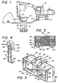
- the reference numeral 10 indicates the apparatus mounted on the end of hydraulically operated booms 12 and 13 of a substantially conventional backhoe apparatus 14 positioned on the working side 15 of a pipeline ditch 16 having a pipeline 18 in the bottom thereof to be covered with fine earth padding material 20 from the ditch excavated backfill soil 22.
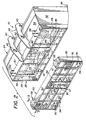
- the apparatus 10 comprises a unitary backhoe bucket 24 and a rectangular screen support frame 26, the frame 26 having elongated end members 28 and 29 joined with longitudinally extending elongated members 30 and 31. Bucket end walls 32 and 33 are joined in parallel relation to the support frame end walls 28 and 29, respectively.
- Bucket side walls 34 and 35 are similarly joined along one edge to the support frame side members 30 and 31, respectively, and project in diverging relation therefrom and are secured at their respective end edges to the edges of the bucket end walls 32 and 33, respectively.
- a bucket fill opening opposite the support frame 26 which has a coextensive scraper blade 36 longitudinally secured to the bucket wall 35 along its edge opposite the support frame 26.
- a pair of planar fins 38 are secured in edgewise parallel spaced apart relation to the outer surface of the bucket wall 34 medially its ends which act as a stiffener for the bucket side wall 34 and are line drilled, as at 40 and 42, to form two pairs of openings which respectively receive backhoe boom pins 41 and 43 permitting the backhoe operator to manipulate the bucket 24 in a manner conventional with backhoe operation.
- the bucket is transversely divided medially its ends by a wedge shaped partition 44 having its apex 45 disposed in the plane defined by the bucket end and side walls marginal edge opposite the support frame 26.
- the bucket walls are also further strengthened by a coextensive inturned lip 46 secured to the screen support frame 26, at its juncture with the bucket side and end walls, which also includes a transverse panel 48 overlying base edge of the wedge shaped partition 44.
- the screen support frame 26 loosely receives a vibratable elongated rectangular screen frame 50 formed by parallel end members 52 and 53 joined by elongated side members 54 and 55.
- the frame 50 is loosely mounted within the support frame 26 by stud bolts 56 projecting through the respective frame wall and entering resilient mounts 58 strategically located between confronting surfaces of the walls of the support frame 26 and screen frame 50.
- Each of the resilient mounts 58 comprises a section of resilient material 60, such as rubber, having a pair of plates 62 and 64 flatly secured to its opposing surfaces.
- Each of the plates being provided with threaded sockets 66 which cooperatively receive the stud bolts 56.
- the screen frame 50 is transversely divided by a pair of parallel spaced apart panels 67 joined by a companion panel 68 which form in combination with frame longitudinal members 54 and 55 an open box which cooperatively nests a vibrator assembly 70 (Fig. 4), as presently described in further detail.
- Each end portion of the screen frame 50 between its respective end wall and the adjacent central panel is longitudinally and transversely provided with interlocking brace members 72 and 74 to strengthen the frame 50 and provide screen support surfaces in the plane of the marginal edge of the screen frame 50 opposite the bucket frame 24.
- a screen 76 of selected mesh, dimensioned to be coextensive with the area defined by the marginal edges of the end and side walls of the frame 50 is secured to its edge surface and brace members 72 and 74 opposite the bucket 24.
- the vibrator assembly 70 comprises an eccentric 78 mounted on a shaft 80 journalled at its respective end portions by pillow block bearings 82 secured to the screen frame panel 68 (Fig. 2).
- a coupling 84 joins the shaft 80 to the drive shaft of a hydraulic motor 86 similarly mounted on the panel 67 and provided with hydraulic couplings.
- the backhoe In operation the backhoe is positioned at the working side 15 of the pipeline ditch 16, opposite the excavated soil 22, and its boom arms 12 and 13 are extended across the ditch and manipulate the bucket 24 in a soil pick-up action by its cutting blade 36 in a conventional manner.
- the filled bucket 24 is then tilted to position its front opening edge upwardly and the screen frame 50 downwardly, as illustrated by Fig. 1, over the position of the ditch 16.
- the vibrator motor 86 operating the eccentric 78 the screen assembly 50 is longitudinally and vertically vibrated .
- the fine padding soil 20 falls by gravity over the pipeline 18.
- the screened out rock or other debris in the bucket 24 is released into the ditch as backfill over the padding material by inverting the bucket from the position shown in Fig. 1, thus, completing one cycle of operation.
Landscapes
- Engineering & Computer Science (AREA)
- Mining & Mineral Resources (AREA)
- Mechanical Engineering (AREA)
- Civil Engineering (AREA)
- General Engineering & Computer Science (AREA)
- Structural Engineering (AREA)
- Shovels (AREA)
- Investigation Of Foundation Soil And Reinforcement Of Foundation Soil By Compacting Or Drainage (AREA)
- Insulated Conductors (AREA)
- Surface Heating Bodies (AREA)
- Massaging Devices (AREA)
- Sewage (AREA)
Claims (9)
- Dispositif de remblayage par benne (10) sur tubes ou sur câbles pouvant être attaché à un bras (13) d'un véhicule de terrassement mobile (14) comportant :un cadre de support (26) possédant des éléments parallèles d'extrémité (28,29), joints respectivement de façon coopérative et orthogonale à des éléments latéraux longitudinaux (30,31) ;des parois d'extrémité (32,33)formant benne (24) fixées auxdits éléments d'extrémité (28,29) de cadre de support (26) en relation parallèle coopérative;des parois latérales (34,35) formant benne (24) possédant des bords adjacents fixés de façon coopérative aux éléments latéraux (30,31) respectifs du cadre de support (26) et aux parois d'extrémité (32,33) de benne avec disposition divergente d'une première paroi latérale de benne (34) et de l'autre paroi latérale (35) de benne afin de constituer une benne (24) ayant une ouverture de ramassage de sol de dimension de périmètre supérieure à la dimension de périmètre dudit cadre de support ;une lame de raclage (36) fixée à un bord de l'une (35) desdites parois latérales de benne à l'opposé dudit cadre de support (26) ;un cadre de tamis (50) possédant des éléments latéraux de cadre (54,55) et des éléments d'extrémité (52,53) maintenus en relation coopérative au sein du cadre de support (26) selon une relation équidistante prédéterminée par rapport aux éléments d'extrémité respectifs (28,29) du cadre de support (26) et aux éléments latéraux (30,31) pour former une ouverture pour la décharge du sol de remblayage ;un tamis (76) de maillage prédéterminé recouvrant le cadre d'écran (50) à l'opposé de l'ouverture de décharge du sol de remblayage ;
caractérisé par :un rebord coextensif (46) faisant saillie vers l'intérieur depuis la jonction des éléments d'extrémité (28,29) du cadre de support (26) et des éléments latéraux (30,31) avec les parois d'extrémité (32,33) respectives de benne (24) et les parois latérales (34,35) permettant d'empêcher la terre de passer dans l'espace qui se trouve entre ledit cadre de support (26) et les éléments latéraux (54,55) du cadre de tamis (50) et les éléments d'extrémité (52,53) ;un moyen de vibration (70) du cadre de tamis (50) retenu par ledit cadre de tamis (50) comprenant un excentrique (78) permettant de faire vibrer ledit cadre d'écran (50) par rapport à la benne (24) et de séparer les objets de taille relativement importante du sol de remblayage (20) pouvant chuter sous l'effet de la gravité à travers le tamis (76), de sorte que ledit moyen de vibration (70) soit monté du côté de la sortie dudit tamis (50). - Dispositif selon la revendication 1 et comprenant en outre :au minimum un bâti de cadre de tamis flexible (58) intercalé entre lesdites parois latérales du cadre d'écran (50) et les éléments latéraux respectifs du cadre de support (26) définissant l'ouverture de décharge du sol de remblayage (20), chaque bâti flexible (58) comportant :une section d'un matériau de type caoutchouc (60) possédant des surfaces plates opposées ;une plaque (62,64) fixée à plat sur chacune desdites surfaces plates, chacune desdites plaques possédant une douille (66) taraudée ; etun boulon fileté (56) dans chaque douille (66) permettant de fixer les éléments latéraux (34,35) respectifs du cadre de support (26) et les parois latérales respectives du cadre de tamis (50) à ladite plaque adjacente (62,64).
- Dispositif selon la revendication 1 dans lequel ladite benne (24) comprend en outre :une paire d'ailerons (38) perforés transversalement fixés de façon parallèle et équidistante sur une paroi latérale (34) de ladite benne (24) à une position intermédiaire par rapport à ses extrémités et opposée à la paroi latérale de benne (24) pourvue de la lame de raclage (36) pour le raccordement avec le bras de fonctionnement de la benne (13) du véhicule de terrassement mobile (14).
- Dispositif selon la revendication 3, comprenant en outre :au minimum un panneau (67,68) divisant ledit cadre de tamis (50) à une position intermédiaire par rapport à ses parois d'extrémité pour protéger ledit moyen de vibration (70) du sol de remblayage (20) pouvant chuter sous l'effet de la gravité à travers l'écran (76), lorsqu'il est positionné dans ledit dispositif de remblayage.
- Dispositif selon la revendication 4, comprenant en outre :une paroi en forme de coin divisant ladite benne pour détourner le sol dans la benne de façon latérale par rapport aux panneaux de protection de vibreur.
- Dispositif de la revendication 1, caractérisé en outre par les parois (32,33) formant benne se prolongeant vers le haut depuis ledit cadre de support (26).
- Procédé pour le remblayage sur tubes ou sur câbles caractérisé par les étapes suivantes :a) chargement du matériau comportant le matériau de remblayage dans un dispositif selon l'une quelconque des revendications précédentes, etb) vibration de l'ensemble tamis (50) afin de permettre au matériau de remblayage de traverser vers un fossé tout en retenant les matériaux de tailles plus importantes.
- Procédé de la revendication 7 caractérisé en outre par l'étape de chargement de matériau sur l'ensemble tamis (50).
- Procédé selon la revendication 7 ou 8, caractérisé par l'étape de déchargement de matériau retenu par l'ensemble tamis (50) après l'étape de vibration.
Applications Claiming Priority (3)
| Application Number | Priority Date | Filing Date | Title |
|---|---|---|---|
| US08/280,634 US5493796A (en) | 1994-07-25 | 1994-07-25 | Pipeline padding apparatus |
| PCT/US1995/013636 WO1997015734A1 (fr) | 1994-07-25 | 1995-10-23 | Appareil de remplissage de tranchees de pipelines |
| CA002238477A CA2238477A1 (fr) | 1994-07-25 | 1995-10-23 | Appareil de remplissage de tranchees de pipelines |
Publications (3)
| Publication Number | Publication Date |
|---|---|
| EP0865543A1 EP0865543A1 (fr) | 1998-09-23 |
| EP0865543A4 EP0865543A4 (fr) | 1999-12-22 |
| EP0865543B1 true EP0865543B1 (fr) | 2002-10-09 |
Family
ID=27170694
Family Applications (1)
| Application Number | Title | Priority Date | Filing Date |
|---|---|---|---|
| EP95937604A Expired - Lifetime EP0865543B1 (fr) | 1994-07-25 | 1995-10-23 | Appareil de remplissage de tranchees de pipelines |
Country Status (8)
| Country | Link |
|---|---|
| US (1) | US5493796A (fr) |
| EP (1) | EP0865543B1 (fr) |
| AT (1) | ATE225882T1 (fr) |
| AU (1) | AU719948B2 (fr) |
| CA (1) | CA2238477A1 (fr) |
| DE (1) | DE69528538T2 (fr) |
| ES (1) | ES2187579T3 (fr) |
| WO (1) | WO1997015734A1 (fr) |
Families Citing this family (36)
| Publication number | Priority date | Publication date | Assignee | Title |
|---|---|---|---|---|
| US5590482A (en) * | 1995-06-27 | 1997-01-07 | R. A. Hanson Company, Inc. | Excavator and earthen material excavator bucket apparatus |
| US5771612A (en) * | 1996-07-15 | 1998-06-30 | Lynch; Eddie T. | Loader bucket sifting system |
| SE9602798L (sv) * | 1996-07-17 | 1998-01-18 | Stig Pettersson | Skopa |
| DE19727549C2 (de) * | 1997-06-28 | 2000-03-02 | Wirtgen Gmbh | Vorrichtung sowie Verfahren zum Ausheben und Auffüllen von Erdreich |
| US6138837A (en) * | 1998-05-01 | 2000-10-31 | Santa Cruz; Cathy D. | Combination screen/conveyor device removably attachable to a vehicle |
| DE19822325A1 (de) * | 1998-05-19 | 1999-12-09 | Rainer Schrode Gmbh | Verfahren zum Aufbereiten von Bodenaushub |
| US6135290A (en) * | 1998-06-05 | 2000-10-24 | Rockland Manufacturing Company | Sifter attachment for excavating machines and the like |
| DE29811073U1 (de) * | 1998-06-20 | 1998-10-08 | Neuenhauser Maschinenbau Gmbh & Co. Kg, 49828 Neuenhaus | Vorrichtung zum Sieben und/oder Zerkleinern von Siebmaterialien |
| US6033154A (en) * | 1998-08-05 | 2000-03-07 | J.A. Jones Environmental Services Company | Waste processing attachment and method for environmentally treating a waste lagoon |
| USD437602S1 (en) | 1998-12-28 | 2001-02-13 | Hitachi Construction Machinery Co., Ltd. | Hydraulic excavator |
| US6108945A (en) * | 1999-06-10 | 2000-08-29 | Cronk, Jr.; Thomas J. | Clam bucket for use in pipeline padding |
| WO2001068993A1 (fr) * | 2000-03-14 | 2001-09-20 | Htb, Llc | Dispositif servant a separer des materiaux et son procede d'utilisation |
| USD460975S1 (en) | 2001-08-02 | 2002-07-30 | Komatsu Ltd. | Hydraulic excavator |
| AUPS270802A0 (en) * | 2002-05-31 | 2002-06-20 | Turnbull, Sam Dominic Seaton | A screen/mixer |
| US6834447B1 (en) | 2002-06-06 | 2004-12-28 | Albert Ben Currey | Excavator sizing bucket |
| US6725942B2 (en) * | 2002-08-28 | 2004-04-27 | Timothy J. Stevens | Pulverizer |
| US6776013B2 (en) * | 2002-10-30 | 2004-08-17 | Certainteed Corporation | Aerodynamic mineral wool forming bucket |
| US20060210385A1 (en) * | 2005-03-07 | 2006-09-21 | Doug Cook | Skid-steer attachment |
| US7886463B2 (en) * | 2005-06-29 | 2011-02-15 | Worldwide Machinery Pipeline Division | Pipeline padding machine |
| USD534552S1 (en) * | 2005-06-30 | 2007-01-02 | Komatsu Ltd. | Hydraulic excavator |
| US7927059B2 (en) * | 2006-10-11 | 2011-04-19 | Worldwide Machinery Pipeline Division | Pipeline padding machine with a debris-resistant escalator assembly |
| US20080092410A1 (en) * | 2006-10-19 | 2008-04-24 | Layh Ricky L | Pipeline padding machine |
| US7445122B2 (en) * | 2006-11-22 | 2008-11-04 | Albert Ben Currey | Mechanical bucket |
| US7549544B1 (en) * | 2006-11-22 | 2009-06-23 | Albert Ben Currey | Agitator and mechanical bucket for use therewith |
| US8360249B1 (en) * | 2006-11-22 | 2013-01-29 | Albert Ben Currey | Crusher and mechanical bucket for use therewith |
| US7762014B2 (en) | 2008-04-29 | 2010-07-27 | Clark Equipment Company | Bucket debris guard |
| US9080314B1 (en) * | 2013-02-20 | 2015-07-14 | Robert R. Rossi, Jr. | Excavating machinery with bucket for screening and/or mixing excavated material |
| JP6604624B2 (ja) * | 2015-05-11 | 2019-11-13 | キャタピラー エス エー アール エル | 作業機械の自動振動装置 |
| US9644342B1 (en) * | 2015-12-18 | 2017-05-09 | David J. Meyers | Screening bucket system |
| US10111385B2 (en) | 2016-06-24 | 2018-10-30 | Jackrabbit | Nut harvester with separating disks |
| AU2020218530A1 (en) | 2019-02-08 | 2021-08-12 | Jackrabbit, Inc. | A nut harvester with a removable assembly and a method of replacing a removable assembly of a nut harvester |
| USD943009S1 (en) | 2019-11-06 | 2022-02-08 | Albert Ben Currey | Bucket |
| US11446703B2 (en) | 2019-11-06 | 2022-09-20 | Albert Ben Currey | Bucket with vibrating screen |
| CN112459085A (zh) * | 2020-11-23 | 2021-03-09 | 界首市天瓴建筑工程有限公司 | 一种用于向管中填充沙子的辅助装置 |
| CN115450230B (zh) * | 2022-09-29 | 2023-08-08 | 北京久安建设投资集团有限公司 | 一种水利管道铺设用回填装置 |
| CN116267496B (zh) * | 2023-04-07 | 2023-12-19 | 深圳世源工程技术有限公司 | 一种用于环境恢复治理的植被种植装置及方法 |
Family Cites Families (17)
| Publication number | Priority date | Publication date | Assignee | Title |
|---|---|---|---|---|
| US2947096A (en) * | 1957-10-18 | 1960-08-02 | James D Cummings | Dragline ditch padder attachment |
| US3072257A (en) * | 1959-08-21 | 1963-01-08 | Lester W Hockenberry | Combined gravel collecting and screening mechanism |
| US3003265A (en) * | 1959-12-30 | 1961-10-10 | Lutjens Herman | Bucket device |
| US3523380A (en) * | 1968-01-23 | 1970-08-11 | Lyle V Bolyard | Universal backfill and landscaping blade |
| US3732980A (en) * | 1970-07-09 | 1973-05-15 | Gibhardt R Co | Earth moving and screening equipment |
| US3834534A (en) * | 1971-12-20 | 1974-09-10 | Kennecott Copper Corp | Variable mode vibratory screen |
| US3765490A (en) * | 1972-06-29 | 1973-10-16 | G Logue | Combined loader bucket and fines separator |
| CS209900B2 (en) * | 1977-07-26 | 1981-12-31 | Fesch Maschf Ferdinand | Loading shovel,particularly for the agricultural and forest economy |
| US4157956A (en) * | 1978-04-19 | 1979-06-12 | Robinson Leo E | Screening bucket |
| US4698150A (en) * | 1985-09-20 | 1987-10-06 | Luis Wigoda | Beach trash machine |
| US4664791A (en) * | 1986-02-07 | 1987-05-12 | Mcclain Ray | Padding machines |
| US4981396A (en) * | 1989-02-28 | 1991-01-01 | The Charles Machine Works, Inc. | Multiple pipe installation backfilling, and compaction attachment |
| US5398430A (en) * | 1991-05-20 | 1995-03-21 | Scott; Thomas M. | Earth moving and compacting rig |
| US5261171A (en) * | 1990-03-26 | 1993-11-16 | Bishop William B | Pipeline padding machine attachment for a vehicle |
| US5311684A (en) * | 1990-05-04 | 1994-05-17 | Rudolf Van Dalfsen | Scooping apparatus, vehicle and coupling plate therefore |
| US5160034A (en) * | 1990-06-01 | 1992-11-03 | Potter Robert J | Vibrating bucket screen for beaches |
| DE4104950A1 (de) * | 1991-02-18 | 1992-08-20 | Helmut Wack | Schaufel fuer erdbewegungsgeraete |
-
1994
- 1994-07-25 US US08/280,634 patent/US5493796A/en not_active Expired - Lifetime
-
1995
- 1995-10-23 CA CA002238477A patent/CA2238477A1/fr not_active Abandoned
- 1995-10-23 EP EP95937604A patent/EP0865543B1/fr not_active Expired - Lifetime
- 1995-10-23 AU AU39664/95A patent/AU719948B2/en not_active Ceased
- 1995-10-23 DE DE69528538T patent/DE69528538T2/de not_active Expired - Fee Related
- 1995-10-23 AT AT95937604T patent/ATE225882T1/de not_active IP Right Cessation
- 1995-10-23 WO PCT/US1995/013636 patent/WO1997015734A1/fr not_active Ceased
- 1995-10-23 ES ES95937604T patent/ES2187579T3/es not_active Expired - Lifetime
Also Published As
| Publication number | Publication date |
|---|---|
| CA2238477A1 (fr) | 1997-05-01 |
| EP0865543A1 (fr) | 1998-09-23 |
| US5493796A (en) | 1996-02-27 |
| ATE225882T1 (de) | 2002-10-15 |
| AU719948B2 (en) | 2000-05-18 |
| EP0865543A4 (fr) | 1999-12-22 |
| DE69528538T2 (de) | 2003-05-15 |
| DE69528538D1 (de) | 2002-11-14 |
| ES2187579T3 (es) | 2003-06-16 |
| AU3966495A (en) | 1997-05-15 |
| WO1997015734A1 (fr) | 1997-05-01 |
Similar Documents
| Publication | Publication Date | Title |
|---|---|---|
| EP0865543B1 (fr) | Appareil de remplissage de tranchees de pipelines | |
| US7204046B2 (en) | Excavator sizing bucket | |
| US5596824A (en) | Single shovel earth moving and compacting rig | |
| US4664791A (en) | Padding machines | |
| JP2956798B2 (ja) | 土工装置に用いられるショベル | |
| CA2310798C (fr) | Benne preneuse pour utilisation dans le rembourrage des pipelines | |
| US5741087A (en) | Chain separator for padding machine | |
| IES970245A2 (en) | Improvements to screening apparatus | |
| US5540003A (en) | Padding machine with shaker for separator | |
| US11421398B2 (en) | Padding machine | |
| USRE38765E1 (en) | Combination screen/conveyor device removably attachable to a vehicle | |
| USRE34289E (en) | Padding machines | |
| US20200215575A1 (en) | Mobile material sifter | |
| US6718659B2 (en) | Material separating apparatus and method for using same | |
| WO1995026445A1 (fr) | Lame niveleuse a patins vibrants pour la construction de remblais routiers | |
| JP3375574B2 (ja) | 土質改良機械の土砂ホッパ及び自走式土質改良機械 | |
| US3182460A (en) | Apparatus for making permeable conduits in subterranean lines of drainage | |
| JPH07286337A (ja) | 付着物の離間装置及びその装置に用いる連鎖帯 | |
| JPS5816602A (ja) | 牽引式石れき除去装置 | |
| JP3075136U (ja) | ふるい機能付きバケット | |
| GB2312888A (en) | Bucket for excavation and compaction | |
| US5901790A (en) | Earth mover and attached vibratory screen | |
| JPS61130567A (ja) | コンクリ−ト塊及び土石等の分離用バケット | |
| JP2004300917A (ja) | 自走式土質改良機及びこれに用いる篩装置 | |
| JPH0428860B2 (fr) |
Legal Events
| Date | Code | Title | Description |
|---|---|---|---|
| PUAI | Public reference made under article 153(3) epc to a published international application that has entered the european phase |
Free format text: ORIGINAL CODE: 0009012 |
|
| 17P | Request for examination filed |
Effective date: 19980525 |
|
| AK | Designated contracting states |
Kind code of ref document: A1 Designated state(s): AT BE CH DE DK ES FR GB GR IE IT LI LU MC NL PT SE |
|
| RAP1 | Party data changed (applicant data changed or rights of an application transferred) |
Owner name: F & B L.L.C. |
|
| A4 | Supplementary search report drawn up and despatched |
Effective date: 19991110 |
|
| AK | Designated contracting states |
Kind code of ref document: A4 Designated state(s): AT BE CH DE DK ES FR GB GR IE IT LI LU MC NL PT SE |
|
| RIC1 | Information provided on ipc code assigned before grant |
Free format text: 6E 02F 3/76 A, 6E 02F 3/24 B, 6E 02F 5/22 B, 6E 02F 3/40 B |
|
| 17Q | First examination report despatched |
Effective date: 20001207 |
|
| GRAG | Despatch of communication of intention to grant |
Free format text: ORIGINAL CODE: EPIDOS AGRA |
|
| GRAG | Despatch of communication of intention to grant |
Free format text: ORIGINAL CODE: EPIDOS AGRA |
|
| GRAH | Despatch of communication of intention to grant a patent |
Free format text: ORIGINAL CODE: EPIDOS IGRA |
|
| GRAH | Despatch of communication of intention to grant a patent |
Free format text: ORIGINAL CODE: EPIDOS IGRA |
|
| GRAA | (expected) grant |
Free format text: ORIGINAL CODE: 0009210 |
|
| AK | Designated contracting states |
Kind code of ref document: B1 Designated state(s): AT BE CH DE DK ES FR GB GR IE IT LI LU MC NL PT SE |
|
| PG25 | Lapsed in a contracting state [announced via postgrant information from national office to epo] |
Ref country code: NL Free format text: LAPSE BECAUSE OF FAILURE TO SUBMIT A TRANSLATION OF THE DESCRIPTION OR TO PAY THE FEE WITHIN THE PRESCRIBED TIME-LIMIT Effective date: 20021009 Ref country code: LI Free format text: LAPSE BECAUSE OF FAILURE TO SUBMIT A TRANSLATION OF THE DESCRIPTION OR TO PAY THE FEE WITHIN THE PRESCRIBED TIME-LIMIT Effective date: 20021009 Ref country code: GR Free format text: LAPSE BECAUSE OF FAILURE TO SUBMIT A TRANSLATION OF THE DESCRIPTION OR TO PAY THE FEE WITHIN THE PRESCRIBED TIME-LIMIT Effective date: 20021009 Ref country code: CH Free format text: LAPSE BECAUSE OF FAILURE TO SUBMIT A TRANSLATION OF THE DESCRIPTION OR TO PAY THE FEE WITHIN THE PRESCRIBED TIME-LIMIT Effective date: 20021009 Ref country code: BE Free format text: LAPSE BECAUSE OF FAILURE TO SUBMIT A TRANSLATION OF THE DESCRIPTION OR TO PAY THE FEE WITHIN THE PRESCRIBED TIME-LIMIT Effective date: 20021009 Ref country code: AT Free format text: LAPSE BECAUSE OF FAILURE TO SUBMIT A TRANSLATION OF THE DESCRIPTION OR TO PAY THE FEE WITHIN THE PRESCRIBED TIME-LIMIT Effective date: 20021009 |
|
| REF | Corresponds to: |
Ref document number: 225882 Country of ref document: AT Date of ref document: 20021015 Kind code of ref document: T |
|
| REG | Reference to a national code |
Ref country code: GB Ref legal event code: FG4D |
|
| REG | Reference to a national code |
Ref country code: CH Ref legal event code: EP |
|
| PG25 | Lapsed in a contracting state [announced via postgrant information from national office to epo] |
Ref country code: LU Free format text: LAPSE BECAUSE OF NON-PAYMENT OF DUE FEES Effective date: 20021023 Ref country code: IE Free format text: LAPSE BECAUSE OF NON-PAYMENT OF DUE FEES Effective date: 20021023 |
|
| REG | Reference to a national code |
Ref country code: IE Ref legal event code: FG4D |
|
| REF | Corresponds to: |
Ref document number: 69528538 Country of ref document: DE Date of ref document: 20021114 |
|
| PG25 | Lapsed in a contracting state [announced via postgrant information from national office to epo] |
Ref country code: SE Free format text: LAPSE BECAUSE OF FAILURE TO SUBMIT A TRANSLATION OF THE DESCRIPTION OR TO PAY THE FEE WITHIN THE PRESCRIBED TIME-LIMIT Effective date: 20030109 Ref country code: PT Free format text: LAPSE BECAUSE OF FAILURE TO SUBMIT A TRANSLATION OF THE DESCRIPTION OR TO PAY THE FEE WITHIN THE PRESCRIBED TIME-LIMIT Effective date: 20030109 Ref country code: DK Free format text: LAPSE BECAUSE OF FAILURE TO SUBMIT A TRANSLATION OF THE DESCRIPTION OR TO PAY THE FEE WITHIN THE PRESCRIBED TIME-LIMIT Effective date: 20030109 |
|
| NLV1 | Nl: lapsed or annulled due to failure to fulfill the requirements of art. 29p and 29m of the patents act | ||
| REG | Reference to a national code |
Ref country code: CH Ref legal event code: PL |
|
| PG25 | Lapsed in a contracting state [announced via postgrant information from national office to epo] |
Ref country code: MC Free format text: LAPSE BECAUSE OF NON-PAYMENT OF DUE FEES Effective date: 20030501 |
|
| ET | Fr: translation filed | ||
| REG | Reference to a national code |
Ref country code: ES Ref legal event code: FG2A Ref document number: 2187579 Country of ref document: ES Kind code of ref document: T3 |
|
| REG | Reference to a national code |
Ref country code: IE Ref legal event code: MM4A |
|
| PLBE | No opposition filed within time limit |
Free format text: ORIGINAL CODE: 0009261 |
|
| STAA | Information on the status of an ep patent application or granted ep patent |
Free format text: STATUS: NO OPPOSITION FILED WITHIN TIME LIMIT |
|
| 26N | No opposition filed |
Effective date: 20030710 |
|
| REG | Reference to a national code |
Ref country code: ES Ref legal event code: PC2A |
|
| PGFP | Annual fee paid to national office [announced via postgrant information from national office to epo] |
Ref country code: GB Payment date: 20041011 Year of fee payment: 10 Ref country code: ES Payment date: 20041011 Year of fee payment: 10 |
|
| PGFP | Annual fee paid to national office [announced via postgrant information from national office to epo] |
Ref country code: FR Payment date: 20041025 Year of fee payment: 10 |
|
| PGFP | Annual fee paid to national office [announced via postgrant information from national office to epo] |
Ref country code: DE Payment date: 20041029 Year of fee payment: 10 |
|
| PG25 | Lapsed in a contracting state [announced via postgrant information from national office to epo] |
Ref country code: IT Free format text: LAPSE BECAUSE OF NON-PAYMENT OF DUE FEES Effective date: 20051023 Ref country code: GB Free format text: LAPSE BECAUSE OF NON-PAYMENT OF DUE FEES Effective date: 20051023 |
|
| PG25 | Lapsed in a contracting state [announced via postgrant information from national office to epo] |
Ref country code: ES Free format text: LAPSE BECAUSE OF NON-PAYMENT OF DUE FEES Effective date: 20051024 |
|
| PG25 | Lapsed in a contracting state [announced via postgrant information from national office to epo] |
Ref country code: DE Free format text: LAPSE BECAUSE OF NON-PAYMENT OF DUE FEES Effective date: 20060503 |
|
| GBPC | Gb: european patent ceased through non-payment of renewal fee |
Effective date: 20051023 |
|
| PG25 | Lapsed in a contracting state [announced via postgrant information from national office to epo] |
Ref country code: FR Free format text: LAPSE BECAUSE OF NON-PAYMENT OF DUE FEES Effective date: 20060630 |
|
| REG | Reference to a national code |
Ref country code: FR Ref legal event code: ST Effective date: 20060630 |
|
| REG | Reference to a national code |
Ref country code: ES Ref legal event code: FD2A Effective date: 20051024 |