EP0865573B1 - Ventilnadel für ein einspritzventil - Google Patents
Ventilnadel für ein einspritzventil Download PDFInfo
- Publication number
- EP0865573B1 EP0865573B1 EP97939954A EP97939954A EP0865573B1 EP 0865573 B1 EP0865573 B1 EP 0865573B1 EP 97939954 A EP97939954 A EP 97939954A EP 97939954 A EP97939954 A EP 97939954A EP 0865573 B1 EP0865573 B1 EP 0865573B1
- Authority
- EP
- European Patent Office
- Prior art keywords
- valve
- connecting part
- closing element
- opening
- valve closing
- Prior art date
- Legal status (The legal status is an assumption and is not a legal conclusion. Google has not performed a legal analysis and makes no representation as to the accuracy of the status listed.)
- Expired - Lifetime
Links
- 238000002347 injection Methods 0.000 claims description 16
- 239000007924 injection Substances 0.000 claims description 16
- 239000000446 fuel Substances 0.000 claims description 8
- 238000002485 combustion reaction Methods 0.000 claims description 4
- 239000002184 metal Substances 0.000 claims description 3
- 239000007787 solid Substances 0.000 claims description 3
- 239000012530 fluid Substances 0.000 claims description 2
- 238000010276 construction Methods 0.000 claims 1
- 239000007921 spray Substances 0.000 description 13
- 230000005291 magnetic effect Effects 0.000 description 7
- 238000003466 welding Methods 0.000 description 4
- 238000009413 insulation Methods 0.000 description 3
- 238000003825 pressing Methods 0.000 description 3
- 238000011144 upstream manufacturing Methods 0.000 description 3
- 238000001746 injection moulding Methods 0.000 description 2
- 238000003780 insertion Methods 0.000 description 2
- 230000037431 insertion Effects 0.000 description 2
- 238000009434 installation Methods 0.000 description 2
- 238000004519 manufacturing process Methods 0.000 description 2
- 239000000463 material Substances 0.000 description 2
- 238000000034 method Methods 0.000 description 2
- 229910000760 Hardened steel Inorganic materials 0.000 description 1
- 229910000831 Steel Inorganic materials 0.000 description 1
- 230000015572 biosynthetic process Effects 0.000 description 1
- 239000002131 composite material Substances 0.000 description 1
- 230000006835 compression Effects 0.000 description 1
- 238000007906 compression Methods 0.000 description 1
- 238000001816 cooling Methods 0.000 description 1
- 238000013016 damping Methods 0.000 description 1
- 238000011161 development Methods 0.000 description 1
- 230000018109 developmental process Effects 0.000 description 1
- 238000005516 engineering process Methods 0.000 description 1
- 230000003628 erosive effect Effects 0.000 description 1
- 238000005530 etching Methods 0.000 description 1
- 238000001125 extrusion Methods 0.000 description 1
- 230000005294 ferromagnetic effect Effects 0.000 description 1
- 238000010438 heat treatment Methods 0.000 description 1
- 238000005304 joining Methods 0.000 description 1
- 239000000696 magnetic material Substances 0.000 description 1
- 239000000203 mixture Substances 0.000 description 1
- 238000004080 punching Methods 0.000 description 1
- 238000005507 spraying Methods 0.000 description 1
- 239000010959 steel Substances 0.000 description 1
- 238000002604 ultrasonography Methods 0.000 description 1
- 238000009736 wetting Methods 0.000 description 1
- 238000004804 winding Methods 0.000 description 1
Images

Classifications
-
- F—MECHANICAL ENGINEERING; LIGHTING; HEATING; WEAPONS; BLASTING
- F02—COMBUSTION ENGINES; HOT-GAS OR COMBUSTION-PRODUCT ENGINE PLANTS
- F02M—SUPPLYING COMBUSTION ENGINES IN GENERAL WITH COMBUSTIBLE MIXTURES OR CONSTITUENTS THEREOF
- F02M51/00—Fuel-injection apparatus characterised by being operated electrically
- F02M51/06—Injectors peculiar thereto with means directly operating the valve needle
-
- F—MECHANICAL ENGINEERING; LIGHTING; HEATING; WEAPONS; BLASTING
- F02—COMBUSTION ENGINES; HOT-GAS OR COMBUSTION-PRODUCT ENGINE PLANTS
- F02M—SUPPLYING COMBUSTION ENGINES IN GENERAL WITH COMBUSTIBLE MIXTURES OR CONSTITUENTS THEREOF
- F02M61/00—Fuel-injectors not provided for in groups F02M39/00 - F02M57/00 or F02M67/00
- F02M61/16—Details not provided for in, or of interest apart from, the apparatus of groups F02M61/02 - F02M61/14
- F02M61/166—Selection of particular materials
-
- F—MECHANICAL ENGINEERING; LIGHTING; HEATING; WEAPONS; BLASTING
- F02—COMBUSTION ENGINES; HOT-GAS OR COMBUSTION-PRODUCT ENGINE PLANTS
- F02M—SUPPLYING COMBUSTION ENGINES IN GENERAL WITH COMBUSTIBLE MIXTURES OR CONSTITUENTS THEREOF
- F02M51/00—Fuel-injection apparatus characterised by being operated electrically
- F02M51/06—Injectors peculiar thereto with means directly operating the valve needle
- F02M51/061—Injectors peculiar thereto with means directly operating the valve needle using electromagnetic operating means
- F02M51/0625—Injectors peculiar thereto with means directly operating the valve needle using electromagnetic operating means characterised by arrangement of mobile armatures
- F02M51/0664—Injectors peculiar thereto with means directly operating the valve needle using electromagnetic operating means characterised by arrangement of mobile armatures having a cylindrically or partly cylindrically shaped armature, e.g. entering the winding; having a plate-shaped or undulated armature entering the winding
- F02M51/0671—Injectors peculiar thereto with means directly operating the valve needle using electromagnetic operating means characterised by arrangement of mobile armatures having a cylindrically or partly cylindrically shaped armature, e.g. entering the winding; having a plate-shaped or undulated armature entering the winding the armature having an elongated valve body attached thereto
-
- F—MECHANICAL ENGINEERING; LIGHTING; HEATING; WEAPONS; BLASTING
- F02—COMBUSTION ENGINES; HOT-GAS OR COMBUSTION-PRODUCT ENGINE PLANTS
- F02M—SUPPLYING COMBUSTION ENGINES IN GENERAL WITH COMBUSTIBLE MIXTURES OR CONSTITUENTS THEREOF
- F02M51/00—Fuel-injection apparatus characterised by being operated electrically
- F02M51/06—Injectors peculiar thereto with means directly operating the valve needle
- F02M51/061—Injectors peculiar thereto with means directly operating the valve needle using electromagnetic operating means
- F02M51/0625—Injectors peculiar thereto with means directly operating the valve needle using electromagnetic operating means characterised by arrangement of mobile armatures
- F02M51/0664—Injectors peculiar thereto with means directly operating the valve needle using electromagnetic operating means characterised by arrangement of mobile armatures having a cylindrically or partly cylindrically shaped armature, e.g. entering the winding; having a plate-shaped or undulated armature entering the winding
- F02M51/0685—Injectors peculiar thereto with means directly operating the valve needle using electromagnetic operating means characterised by arrangement of mobile armatures having a cylindrically or partly cylindrically shaped armature, e.g. entering the winding; having a plate-shaped or undulated armature entering the winding the armature and the valve being allowed to move relatively to each other or not being attached to each other
-
- F—MECHANICAL ENGINEERING; LIGHTING; HEATING; WEAPONS; BLASTING
- F02—COMBUSTION ENGINES; HOT-GAS OR COMBUSTION-PRODUCT ENGINE PLANTS
- F02M—SUPPLYING COMBUSTION ENGINES IN GENERAL WITH COMBUSTIBLE MIXTURES OR CONSTITUENTS THEREOF
- F02M61/00—Fuel-injectors not provided for in groups F02M39/00 - F02M57/00 or F02M67/00
- F02M61/16—Details not provided for in, or of interest apart from, the apparatus of groups F02M61/02 - F02M61/14
- F02M61/168—Assembling; Disassembling; Manufacturing; Adjusting
-
- F—MECHANICAL ENGINEERING; LIGHTING; HEATING; WEAPONS; BLASTING
- F02—COMBUSTION ENGINES; HOT-GAS OR COMBUSTION-PRODUCT ENGINE PLANTS
- F02M—SUPPLYING COMBUSTION ENGINES IN GENERAL WITH COMBUSTIBLE MIXTURES OR CONSTITUENTS THEREOF
- F02M2200/00—Details of fuel-injection apparatus, not otherwise provided for
- F02M2200/30—Fuel-injection apparatus having mechanical parts, the movement of which is damped
- F02M2200/306—Fuel-injection apparatus having mechanical parts, the movement of which is damped using mechanical means
Definitions
- the invention is based on a valve needle for Injection valve according to the type of the main claim.
- a valve needle for a Electromagnetically actuated valve known from a Armature, a valve closing member and the armature with the z.
- the single ones Sections represent separately manufactured sections Items that are only by means of joining processes, e.g. B. by Laser welding, can be connected to each other.
- the anchor encompasses the connecting tube completely radially and at least partially axially, since the connecting tube in one through the longitudinal opening of the anchor is attached.
- the Connecting tube itself also has a continuous inner Longitudinal opening in which fuel towards Valve closing member can flow, which is then close to the Valve closing member through in the wall of the Connecting pipe inserted, radially extending Cross openings emerges.
- the fuel flow therefore takes place first inside the valve needle and leaves the First push the valve needle towards the valve seat.
- a cup-shaped anchor is included firmly with an elongated, rod-shaped, metallic Connection part connected at its downstream end immediately a spherical segment Valve closing section is formed. From the bottom part of the a connection piece runs out of the cup-shaped anchor, which has an inner opening. The inner opening is with several axially successive grooves provided so that areas larger and smaller diameter in the opening. The connecting part projects with its valve closing section opposite end, which is also grooved, into the Opening the connector into it, causing both metal components are positively connected are.
- From DE-OS 195 03 224 is also already one three-part valve needle for electromagnetically actuated Injectors known from a tubular armature, a sleeve-shaped connecting part and a spherical one Valve closing body is formed. That from a plastic manufactured connecting part engages on the outer circumference the anchor locking elements for firmly connecting the anchor and Connecting part. The downstream end of the Connecting part has a dome-shaped recess, in which the spherical valve closing body snapped or clipped. The lower part of the recess is thereby so elastic that it is when the Valve closing body expands to then the Close the valve closing body tightly.
- valve needle according to the invention with the characteristic Features of the main claim has the advantage that they are based on particularly simple and inexpensive way can be produced. Every single component of the valve needle, namely an anchor, a valve closing element and a Anchor connecting to the valve closing element Connection part, due to the very simple Contouring is produced particularly inexpensively and to be edited.
- the one made of plastic Connection part ensures a metal Valve needles lower weight of the valve needle. Especially with Injectors with a wide upstream spray point, at which use relatively elongated valve needles, can by such a design of the connecting part still achieved very good dynamic valve properties become. The damping properties of the plastic ensure also for reduced noise.
- connection part and the valve closing element only one small outer diameter, so that an injection valve with Such a valve needle can be made very slim can.
- the form-fitting designed according to the invention Connection of connecting part and valve closing element is particularly easy to achieve and still very safe. On Loosen the connection during the axial movement of the Valve needle inside the injection valve is with this Connection technology completely excluded.
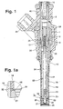
- FIG. 1 shows it Injection valve with a valve needle according to the invention
- Figure 1a shows a section of Figure 1 in the area of a Guide disc for the valve needle
- Figure 2 a Valve needle in a changed scale.
- the valve shown for example in Figure 1 in the Form of an electromagnetically actuated injection valve for fuel injection systems of mixture compression, spark-ignited internal combustion engines has one of one Solenoid 1 surrounded, as a fuel inlet port serving tubular core 2 as a so-called inner pole.
- On Coil body 3 receives a winding of the magnet coil 1 and in connection with the core 2 enables a special compact design of the injection valve in the area of Solenoid coil 1.
- a valve longitudinal axis 10 With a lower core end 9 of the core 2 is concentric a valve longitudinal axis 10 tightly a tubular, metallic Connecting part 12 connected for example by welding and partially surrounds the core end 9 axially.
- a tubular, metallic Connecting part 12 Starting from lower end of the connecting part 12 extends elongated, thin-walled, sleeve-shaped Valve seat support 16, which is tight and firm with the Connecting part 12 is connected and by its relative large axial extent a clearly superior Spray point. That shows near the core end 9 Connecting part 12 has a magnetic throttle point 13, which is characterized by a much smaller wall thickness than that Wall thicknesses of the other sections of the connecting part 12 distinguished. On commonly used non-magnetic Intermediate parts can thus be dispensed with.
- a longitudinal opening 17 which is concentric with the Longitudinal valve axis 10 is formed and on the wall thereof optionally insertable, also elongated, sleeve-shaped insulation element 18 fits tightly.
- the Insulating element 18 made of plastic extends over the most of the axial extent of the connecting part 12 and the valve seat support 16 between a cup-shaped Armature 20 and a valve seat body 21.
- the insulation element 18 which is mainly is used for thermal insulation in the valve seat support 16th z. B. firmly pressed.
- the sleeve-shaped Insulating element 18 In the sleeve-shaped Insulating element 18 is in turn an inner, concentric longitudinal opening 19 extending to the longitudinal axis 10 of the valve intended.
- the longitudinal opening 19 In the longitudinal opening 19 is one Solid valve needle 22 according to the invention arranged at its downstream end a z. B. has cylindrical valve closing element 23.
- the entire valve needle 22 is from the armature 20, the Valve closing element 23 and an armature 20 and that Valve closing element 23 connecting, elongated, rod-shaped connecting part 24 is formed.
- Executable valve seat support 16 encloses next to the lower one End of the connecting part 12 also at his opposite end of the valve seat body 21 and one spray plate 25 attached to it. With the elongated Formation of the valve seat support 16 becomes the spray point of the injection valve upstream or far ahead.
- injectors in Internal combustion engines mean that the injector with its downstream end and thus with its metering and Spray area clearly extends into the intake pipe. As a result, targeted spraying on or several inlet valves a wall wetting of the intake pipe largely avoided and, as a result, exhaust emissions the internal combustion engine can be reduced.
- the injection valve is actuated in a known manner Way, in the injector shown in Figure 1 electromagnetically.
- the electromagnetic circuit with the magnetic coil 1, the core 2 and the anchor 20.
- the cup-shaped anchor 20, for example is with the end 28 facing away from the valve closing element 23 of the connecting part 24 firmly connected to the core 2 aligned.
- In the downstream core 2 opposite end of the valve seat support 16 is in the Longitudinal opening 17 of the z.
- the Spray face plate 25 facing away from end face 32 of the Valve seat body 21 attached guide plate 33.
- the Armature 20 is in the connecting part during the axial movement 12 especially in the area of the magnetic throttle point 13 guided.
- the largely cylindrical, facing the valve seat 31 having a contour of a spherical section Valve closing element 23 interacts with the Flow direction frustoconical valve seat 31 of the valve seat body 21 together.
- the Guide disc 33 facing away from the front Valve seat body 21 with the z.
- the spray hole disc 25 has at least one, for example four through Eroding, punching or etching molded injection orifices.
- a holding edge of the spray plate 25 is conical bent outside so that this at the through the longitudinal opening 17 certain inner wall of the valve seat support 16 is present, with a radial pressure.
- the Spray plate 25 is with the wall of Valve seat support 16 tight, for example by welding connected.
- the insertion depth of the valve seat body 21 determines the Size of the stroke of the valve needle 22.
- the one is End position of the valve needle 22 when not energized Solenoid 1 by the valve closing element 23 fixed to valve seat 31 while the other End position of the valve needle 22 when the solenoid coil 1 is excited results from the installation of the armature 20 at the core end 9.
- the Magnetic coil 1 is of at least one, for example as Bracket trained and as a ferromagnetic element serving guide element 38 surrounding the solenoid 1 in At least partially surrounds the circumferential direction.
- the Injector is outside of valve seat carrier 16 largely enclosed with a plastic extrusion 40, to which, for example, an injected electric Connector 41 belongs.
- FIG. 1a shows a section of that in FIG. 1 Injection valve shown in the region of the guide disk 33 shown enlarged.
- the guide disc 33 is used radial guidance of the valve needle 22 during its axial Movement in the longitudinal opening 17 or 19 to avoid excessive wear on valve seat 31 and asymmetrical Flow conditions between the valve seat 31 and the Spray orifices in the spray plate 25.
- a central one Through hole 43 is provided, which is a slightly larger Diameter as the outside diameter of the Has valve closing element 23 of the valve needle 22. This Dimensional differences lead to a minimal play of approx. 10 ⁇ m.
- Outside of the through hole 43 are in the Guide disk 33 introduced a plurality of passage openings 44, an unimpeded flow against the valve seat 31st to guarantee.
- the passage openings 44 can also be so small (z. B. ⁇ 60 microns) that they are also a Exercise filter function.
- FIG. 2 shows the anchor 20, connecting part 24 and Valve closing element 23 composite valve needle 22 in different scale as a single component.
- the cup-shaped anchor 20 has an axially extending, circumferential jacket part 46 as well as a perpendicular to the valve longitudinal axis 2, flat bottom part 47.
- In the bottom part 47 of the armature 20th are at least one, e.g. B. three or four Through openings 48 provided by the fuel in Flow through to the valve seat 31.
- the fluid, especially a fuel flows downstream of the Through openings 48 on the outer circumference of the Connecting part 24 along in the longitudinal opening 19.
- a central opening 49 is formed in the base part 47, through which the connecting part 24 with its end 28 extends through.
- the one from a soft magnetic Material executed anchor 20 is at its Valve closing element 23 facing away from the top, as a stop serving end face 50 or on the outer circumference of the Jacket part 46 surface-treated and wear-resistant trained, e.g. B. chrome-plated.
- the connecting part 24 has at its upper, with the Anchor 20 connected end 28 a z.
- the annular groove 52 has a axial extension, which is approximately the thickness of the bottom part 47 corresponds to the armature 20, since the bottom part 47 is form-fitting engages in the annular groove 52, so that the diameter of the Groove bottom of the annular groove 52 and the diameter of the opening 49 of the anchor 20 are the same size.
- the end 28 of Connection part 24 is designed such that it is a short Piece still protrudes into the interior of the armature 20.
- the connecting part 24 consists of a Plastic, the production for example by means of Injection molding takes place. The insertion of the connecting part 24 takes place in the opening 49 of the armature 20, for example by pressing, pressing or in a hot riveting process.
- the opening 57 has its axial Extending several orbiting, successive, however each have spaced apart grooves 58. So that the opening 57 is alternating with several axially successive areas larger and smaller Designed diameter.
- valve closing element 23 its upper, engaging in the connecting part 24 Section 59 with a negative structure for opening 57 is trained, so areas larger and smaller Has alternating diameter, is a dimensionally accurate, Secure positive locking of the valve closing element 23 guaranteed in the opening 57.
- Section 59 of the valve closing element 23 ends the armature 20 turned away from a lower paragraph 60, from which the Valve closing element 23 downstream with a larger one Diameter than that of the section 59 is formed and the z. B. on the lower end face 61 of the connecting part 24 is present.
- the one following downstream of paragraph 60 very much exactly manufactured area of the z. B. stainless, hardened steel existing valve closing element 23, as already mentioned, in the through hole 43 of the Guide disc 33 out.
- this downstream of the Paragraph 60 area has the Valve closing element 23, for example, a smaller one Outside diameter as the connecting part 24 over the largest Part of its axial extension.
- valve closing element 23 and connecting part 24 are, for example, by pressing or pushing the valve closing element 23 into the opening 57 reached.
- the valve closing element 23 can, however also directly in the plastic injection molding process for the production of Connection part 24 are overmolded as an insert.
- a snap-in of the valve closing element 23 conceivable, the areas of smaller diameter of Opening 57 e.g. are beveled so that there are several sawtooth-like sections successively in the Opening 57 result.
- Another way of bringing in the valve closing element 23 is that Valve closing element 23 is heated and into opening 57 is sunk.
- the valve closing element 23 be exposed to ultrasound, causing heating occurs so that the plastic of the connecting part 24 is close the opening 57 when the valve closing element 23 is inserted is partially melted. After cooling, there is one positive connection.
Landscapes
- Engineering & Computer Science (AREA)
- Chemical & Material Sciences (AREA)
- Combustion & Propulsion (AREA)
- Mechanical Engineering (AREA)
- General Engineering & Computer Science (AREA)
- Physics & Mathematics (AREA)
- Electromagnetism (AREA)
- Manufacturing & Machinery (AREA)
- Fuel-Injection Apparatus (AREA)
Description
Claims (8)
- Ventilnadel für ein Einspritzventil, insbesondere für ein elektromagnetisch betätigbares Einspritzventil für Brennstoffeinspritzanlagen von Brennkraftmaschinen, das einen Kern (2), eine Magnetspule (1) und einen festen Ventilsitz (31) hat, mit dem die aus einem Anker (20) und einem metallenen Ventilschließelement (23) bestehende Ventilnadel (22) zusammenwirkt, wobei ein separat von Anker (20) und Ventilschließelement (23) hergestelltes Verbindungsteil (24) als Teil der Ventilnadel (22) vorgesehen ist, das den Anker (20) mit dem Ventilschließelement (23) verbindet, das Verbindungsteil massiv aus einem Kunststoff ausgebildet ist, wobei das Verbindungsteil (24) ausgehend von seiner unteren Stirnseite (61) eine in Richtung zum Anker (20) hin verlaufende und einen Grund aufweisende Öffnung (57) hat, die wenigstens zwei abwechselnd aufeinanderfolgende Bereiche größeren und kleineren Durchmessers aufweist und in die das Ventilschließelement (23) mit einem Abschnitt (59) formschlüssig eingreift.
- Ventilnadel nach Anspruch 1, dadurch gekennzeichnet, daß das Ventilschließelement (23) bolzenartig ausgeführt ist.
- Ventilnadel nach Anspruch 1 oder 2, dadurch gekennzeichnet, daß der in die Öffnung (57) des Verbindungsteils (24) eingreifende Abschnitt (59) des Ventilschließelements (23) mit wenigstens zwei aufeinanderfolgenden Bereichen unterschiedlichen Durchmessers ausgebildet ist.
- Ventilnadel nach Anspruch 1, dadurch gekennzeichnet, daß die Bereiche größeren Durchmessers in der Öffnung (57) des Verbindungsteiles (24) umlaufende Rillen (58) sind.
- Ventilnadel nach einem der vorhergehenden Ansprüche, dadurch gekennzeichnet, daß das Ventilschließelement (23) einen Absatz (60) an seinem äußeren Umfang besitzt, mit dem das Ventilschließelement (23) an der unteren Stirnseite (61) des Verbindungsteils (24) anliegt, wobei der vom Absatz (60) ausgehend in die Öffnung (57) ragende Abschnitt (59) kleinere Durchmesser hat als der außerhalb der Öffnung (57) liegende Teil des Ventilschließelements (23).
- Ventilnadel nach einem der vorhergehenden Ansprüche, dadurch gekennzeichnet, daß das Verbindungsteil (24) stangenförmig massiv aus Kunststoff ausgeformt ist.
- Ventilnadel nach Anspruch 1, dadurch gekennzeichnet, daß der Anker (20) topfförmig mit einem Mantelteil (46) und einem Bodenteil (47) ausgebildet ist, wobei in dem Bodenteil (47) wenigstens eine Durchgangsöffnung (48) für ein Fluid sowie eine Öffnung (49), durch die sich das Verbindungsteil (24) hindurch erstreckt, vorgesehen sind.
- Ventilnadel nach Anspruch 7, dadurch gekennzeichnet, daß am Umfang des dem Anker (20) zugewandten Endes (28) des Verbindungsteils (24) eine umlaufende Ringnut (52) eingebracht ist, in die das Bodenteil (47) des Ankers (20) mit der Wandung der Öffnung (49) formschlüssig eingreift.
Applications Claiming Priority (3)
| Application Number | Priority Date | Filing Date | Title |
|---|---|---|---|
| DE19641785A DE19641785C2 (de) | 1996-10-10 | 1996-10-10 | Ventilnadel für ein Einspritzventil |
| DE19641785 | 1996-10-10 | ||
| PCT/DE1997/001761 WO1998015733A1 (de) | 1996-10-10 | 1997-08-16 | Ventilnadel für ein einspritzventil |
Publications (2)
| Publication Number | Publication Date |
|---|---|
| EP0865573A1 EP0865573A1 (de) | 1998-09-23 |
| EP0865573B1 true EP0865573B1 (de) | 2003-04-09 |
Family
ID=7808371
Family Applications (1)
| Application Number | Title | Priority Date | Filing Date |
|---|---|---|---|
| EP97939954A Expired - Lifetime EP0865573B1 (de) | 1996-10-10 | 1997-08-16 | Ventilnadel für ein einspritzventil |
Country Status (6)
| Country | Link |
|---|---|
| US (1) | US6390392B1 (de) |
| EP (1) | EP0865573B1 (de) |
| JP (1) | JP2000502422A (de) |
| KR (1) | KR19990071854A (de) |
| DE (2) | DE19641785C2 (de) |
| WO (1) | WO1998015733A1 (de) |
Families Citing this family (39)
| Publication number | Priority date | Publication date | Assignee | Title |
|---|---|---|---|---|
| US6047907A (en) | 1997-12-23 | 2000-04-11 | Siemens Automotive Corporation | Ball valve fuel injector |
| JP4583693B2 (ja) | 2000-02-02 | 2010-11-17 | シーメンス ヴィディーオー オートモティヴ コーポレイション | 燃料噴射器のフィルター兼アジャスタ |
| US6676044B2 (en) | 2000-04-07 | 2004-01-13 | Siemens Automotive Corporation | Modular fuel injector and method of assembling the modular fuel injector |
| US6604510B2 (en) | 2000-10-04 | 2003-08-12 | Siemens Automotive Corporation | Fuel system including a fuel injector directly mounted to a fuel rail |
| US6598592B2 (en) | 2000-10-04 | 2003-07-29 | Seimens Automotive Corporation | Fuel system including a fuel injector internally mounted to a fuel rail |
| US6631857B2 (en) | 2000-12-22 | 2003-10-14 | Caterpillar Inc | Partially plastic fuel injector component and method of making the same |
| US6655609B2 (en) | 2000-12-29 | 2003-12-02 | Siemens Automotive Corporation | Modular fuel injector having a low mass, high efficiency electromagnetic actuator and having an integral filter and o-ring retainer assembly |
| US6543707B2 (en) * | 2000-12-29 | 2003-04-08 | Siemens Automotive Corporation | Modular fuel injector having a lift set sleeve |
| US6511003B2 (en) | 2000-12-29 | 2003-01-28 | Siemens Automotive Corporation | Modular fuel injector having an integral or interchangeable inlet tube and having a terminal connector interconnecting an electromagnetic actuator with an electrical terminal |
| US6565019B2 (en) | 2000-12-29 | 2003-05-20 | Seimens Automotive Corporation | Modular fuel injector having a snap-on orifice disk retainer and having an integral filter and O-ring retainer assembly |
| US6523756B2 (en) * | 2000-12-29 | 2003-02-25 | Siemens Automotive Corporation | Modular fuel injector having a low mass, high efficiency electromagnetic actuator and having a lift set sleeve |
| US6533188B1 (en) | 2000-12-29 | 2003-03-18 | Siemens Automotive Corporation | Modular fuel injector having a snap-on orifice disk retainer and having an integral filter and dynamic adjustment assembly |
| US6695232B2 (en) | 2000-12-29 | 2004-02-24 | Siemens Automotive Corporation | Modular fuel injector having interchangeable armature assemblies and having a lift set sleeve |
| US6520422B2 (en) | 2000-12-29 | 2003-02-18 | Siemens Automotive Corporation | Modular fuel injector having a low mass, high efficiency electromagnetic actuator and having a terminal connector interconnecting an electromagnetic actuator with an electrical terminal |
| US6499677B2 (en) | 2000-12-29 | 2002-12-31 | Siemens Automotive Corporation | Modular fuel injector having a low mass, high efficiency electromagnetic actuator and having an integral filter and dynamic adjustment assembly |
| US6523760B2 (en) | 2000-12-29 | 2003-02-25 | Siemens Automotive Corporation | Modular fuel injector having interchangeable armature assemblies and having a terminal connector interconnecting an electromagnetic actuator with an electrical terminal |
| US6523761B2 (en) | 2000-12-29 | 2003-02-25 | Siemens Automotive Corporation | Modular fuel injector having an integral or interchangeable inlet tube and having a lift set sleeve |
| US6520421B2 (en) | 2000-12-29 | 2003-02-18 | Siemens Automotive Corporation | Modular fuel injector having an integral filter and o-ring retainer |
| US6698664B2 (en) | 2000-12-29 | 2004-03-02 | Siemens Automotive Corporation | Modular fuel injector having an integral or interchangeable inlet tube and having an integral filter and dynamic adjustment assembly |
| US6508417B2 (en) | 2000-12-29 | 2003-01-21 | Siemens Automotive Corporation | Modular fuel injector having a snap-on orifice disk retainer and having a lift set sleeve |
| US6550690B2 (en) | 2000-12-29 | 2003-04-22 | Siemens Automotive Corporation | Modular fuel injector having interchangeable armature assemblies and having an integral filter and dynamic adjustment assembly |
| US6568609B2 (en) | 2000-12-29 | 2003-05-27 | Siemens Automotive Corporation | Modular fuel injector having an integral or interchangeable inlet tube and having an integral filter and o-ring retainer assembly |
| US6607143B2 (en) | 2000-12-29 | 2003-08-19 | Siemens Automotive Corporation | Modular fuel injector having a surface treatment on an impact surface of an electromagnetic actuator and having a lift set sleeve |
| US6769636B2 (en) | 2000-12-29 | 2004-08-03 | Siemens Automotive Corporation | Modular fuel injector having interchangeable armature assemblies and having an integral filter and O-ring retainer assembly |
| US6708906B2 (en) | 2000-12-29 | 2004-03-23 | Siemens Automotive Corporation | Modular fuel injector having a surface treatment on an impact surface of an electromagnetic actuator and having an integral filter and dynamic adjustment assembly |
| US6811091B2 (en) | 2000-12-29 | 2004-11-02 | Siemens Automotive Corporation | Modular fuel injector having an integral filter and dynamic adjustment assembly |
| US6499668B2 (en) * | 2000-12-29 | 2002-12-31 | Siemens Automotive Corporation | Modular fuel injector having a surface treatment on an impact surface of an electromagnetic actuator and having a terminal connector interconnecting an electromagnetic actuator with an electrical terminal |
| US6502770B2 (en) | 2000-12-29 | 2003-01-07 | Siemens Automotive Corporation | Modular fuel injector having a snap-on orifice disk retainer and having a terminal connector interconnecting an electromagnetic actuator with an electrical terminal |
| US6547154B2 (en) * | 2000-12-29 | 2003-04-15 | Siemens Automotive Corporation | Modular fuel injector having a terminal connector interconnecting an electromagnetic actuator with a pre-bent electrical terminal |
| US6536681B2 (en) | 2000-12-29 | 2003-03-25 | Siemens Automotive Corporation | Modular fuel injector having a surface treatment on an impact surface of an electromagnetic actuator and having an integral filter and O-ring retainer assembly |
| US6648247B2 (en) | 2001-02-02 | 2003-11-18 | Siemens Automotive Corporation | Combined filter and adjuster for a fuel injector |
| US6904668B2 (en) | 2001-03-30 | 2005-06-14 | Siemens Vdo Automotive Corp. | Method of manufacturing a modular fuel injector |
| US7093362B2 (en) | 2001-03-30 | 2006-08-22 | Siemens Vdo Automotive Corporation | Method of connecting components of a modular fuel injector |
| US6676043B2 (en) | 2001-03-30 | 2004-01-13 | Siemens Automotive Corporation | Methods of setting armature lift in a modular fuel injector |
| DE10119982A1 (de) | 2001-04-24 | 2002-10-31 | Bosch Gmbh Robert | Kraftstoffeinspritzeinrichtung für eine Brennkraftmaschine |
| TWI295336B (en) * | 2004-09-13 | 2008-04-01 | Guk Hyun Park | Fuel injection system |
| DE102004047041B4 (de) * | 2004-09-28 | 2017-06-14 | Robert Bosch Gmbh | Brennstoffeinspritzventil |
| JP5494680B2 (ja) * | 2012-01-13 | 2014-05-21 | 株式会社デンソー | 電磁弁 |
| GB2637174A (en) * | 2024-01-12 | 2025-07-16 | Phinia Delphi Luxembourg Sarl | Improvements relating to fuel injectors for gaseous fuels and related production methods |
Family Cites Families (16)
| Publication number | Priority date | Publication date | Assignee | Title |
|---|---|---|---|---|
| AT229086B (de) * | 1961-06-21 | 1963-08-26 | Friedmann & Maier Ag | Einspritzdüse |
| FR2058547A5 (de) * | 1969-09-15 | 1971-05-28 | Roto Diesel Sa | |
| SU596746A1 (ru) * | 1976-03-09 | 1978-03-05 | Центральная Научно-Исследовательская Лаборатория Государственного Производственного Объединения "Укрнефть" | Неразъемное соединение с нат гом |
| US4497298A (en) * | 1984-03-08 | 1985-02-05 | General Motors Corporation | Diesel fuel injection pump with solenoid controlled low-bounce valve |
| IT1183213B (it) * | 1985-02-07 | 1987-10-15 | Alfa Romeo Spa | Inietore elettrimagnetico per un motore a c.i. |
| US4610080A (en) * | 1985-07-29 | 1986-09-09 | Allied Corporation | Method for controlling fuel injector lift |
| DE3539056A1 (de) * | 1985-11-04 | 1987-05-14 | Vdo Schindling | Elektromagnetisch betaetigbares kraftstoffeinspritzventil |
| GB8710976D0 (en) * | 1987-05-08 | 1987-06-10 | Lucas Ind Plc | Fuel injection nozzle |
| JP2587999B2 (ja) * | 1988-08-10 | 1997-03-05 | 川崎重工業株式会社 | 予蒸発型液体燃料噴霧器 |
| DE4008675A1 (de) * | 1990-03-17 | 1991-09-19 | Bosch Gmbh Robert | Elektromagnetisch betaetigbares ventil |
| JPH07167004A (ja) * | 1993-12-14 | 1995-07-04 | Toyota Motor Corp | 燃料噴射弁 |
| DE4409848A1 (de) * | 1994-03-22 | 1995-10-19 | Siemens Ag | Vorrichtung zur Zumessung und Zerstäubung von Fluiden |
| DE19503224A1 (de) * | 1995-02-02 | 1996-08-08 | Bosch Gmbh Robert | Elektromagnetisch betätigbares Einspritzventil für Kraftstoffeinspritzanlagen von Verbrennungsmotoren |
| US5667194A (en) * | 1995-12-11 | 1997-09-16 | Siemens Automotive Corporation | Armature needle valve assembly having plastic connecting means |
| US5678767A (en) * | 1996-03-14 | 1997-10-21 | Siemens Automotive Corporation | Fuel injector with contaminant deflector |
| US5860601A (en) * | 1996-11-08 | 1999-01-19 | Siemens Automotive Corporation | Fuel injector needle tip |
-
1996
- 1996-10-10 DE DE19641785A patent/DE19641785C2/de not_active Expired - Fee Related
-
1997
- 1997-08-16 KR KR1019980704138A patent/KR19990071854A/ko not_active Ceased
- 1997-08-16 DE DE59709782T patent/DE59709782D1/de not_active Expired - Fee Related
- 1997-08-16 WO PCT/DE1997/001761 patent/WO1998015733A1/de not_active Ceased
- 1997-08-16 US US09/077,356 patent/US6390392B1/en not_active Expired - Fee Related
- 1997-08-16 EP EP97939954A patent/EP0865573B1/de not_active Expired - Lifetime
- 1997-08-16 JP JP10517055A patent/JP2000502422A/ja active Pending
Also Published As
| Publication number | Publication date |
|---|---|
| KR19990071854A (ko) | 1999-09-27 |
| DE19641785C2 (de) | 1999-01-28 |
| EP0865573A1 (de) | 1998-09-23 |
| WO1998015733A1 (de) | 1998-04-16 |
| JP2000502422A (ja) | 2000-02-29 |
| DE19641785A1 (de) | 1998-04-23 |
| DE59709782D1 (de) | 2003-05-15 |
| US6390392B1 (en) | 2002-05-21 |
Similar Documents
| Publication | Publication Date | Title |
|---|---|---|
| EP0865573B1 (de) | Ventilnadel für ein einspritzventil | |
| EP0871822B1 (de) | Elektromagnetisch betätigbares ventil | |
| EP0865574B1 (de) | Brennstoffeinspritzventil und verfahren zur herstellung | |
| EP0812389B1 (de) | Brennstoffeinspritzventil | |
| EP0900333B1 (de) | Elektromagnetisch betätigbares ventil | |
| EP1966484B1 (de) | Brennstoffeinspritzventil | |
| EP0718491B1 (de) | Verfahren zur herstellung eines ventiles | |
| EP1062421B1 (de) | Brennstoffeinspritzventil | |
| EP0944769A1 (de) | Brennstoffeinspritzventil | |
| EP1114249B1 (de) | Brennstoffeinspritzventil | |
| DE3825134A1 (de) | Elektromagnetisch betaetigbares ventil und verfahren zur herstellung | |
| EP1966482A1 (de) | Kunststoff-metall-verbindung und brennstoffeinspritzventil mit einer kunststoff-metall-verbindung | |
| DE19756103A1 (de) | Brennstoffeinspritzventil | |
| DE3925212C2 (de) | Elektromagnetisch betätigbares Ventil | |
| EP0460125B1 (de) | Elektromagnetisch betätigbares ventil | |
| EP0383063A1 (de) | Magnetanker | |
| EP0383064A1 (de) | Magnetanker | |
| DE19907860A1 (de) | Brennstoffeinspritzventil | |
| EP1966483A1 (de) | Elektromagnetisch betätigbares ventil | |
| EP1966479B1 (de) | Elektromagnetisch betätigbares ventil | |
| EP0917623A1 (de) | Brennstoffeinspritzventil | |
| DE102004013413A1 (de) | Kraftstoff-Einspritzventil | |
| DE10142974A1 (de) | Brennstoffeinspritzventil | |
| DE102007049966A1 (de) | Brennstoffeinspritzventil und Verfahren zur Montage eines Brennstoffeinspritzventils |
Legal Events
| Date | Code | Title | Description |
|---|---|---|---|
| PUAI | Public reference made under article 153(3) epc to a published international application that has entered the european phase |
Free format text: ORIGINAL CODE: 0009012 |
|
| AK | Designated contracting states |
Kind code of ref document: A1 Designated state(s): DE FR GB IT |
|
| 17P | Request for examination filed |
Effective date: 19981016 |
|
| 17Q | First examination report despatched |
Effective date: 20010222 |
|
| RTI1 | Title (correction) |
Free format text: VALVE NEDDLE FOR AN INJECTOR |
|
| GRAH | Despatch of communication of intention to grant a patent |
Free format text: ORIGINAL CODE: EPIDOS IGRA |
|
| GRAH | Despatch of communication of intention to grant a patent |
Free format text: ORIGINAL CODE: EPIDOS IGRA |
|
| GRAA | (expected) grant |
Free format text: ORIGINAL CODE: 0009210 |
|
| AK | Designated contracting states |
Designated state(s): DE FR GB IT |
|
| PG25 | Lapsed in a contracting state [announced via postgrant information from national office to epo] |
Ref country code: IT Free format text: LAPSE BECAUSE OF FAILURE TO SUBMIT A TRANSLATION OF THE DESCRIPTION OR TO PAY THE FEE WITHIN THE PRESCRIBED TIME-LIMIT;WARNING: LAPSES OF ITALIAN PATENTS WITH EFFECTIVE DATE BEFORE 2007 MAY HAVE OCCURRED AT ANY TIME BEFORE 2007. THE CORRECT EFFECTIVE DATE MAY BE DIFFERENT FROM THE ONE RECORDED. Effective date: 20030409 Ref country code: GB Free format text: LAPSE BECAUSE OF FAILURE TO SUBMIT A TRANSLATION OF THE DESCRIPTION OR TO PAY THE FEE WITHIN THE PRESCRIBED TIME-LIMIT Effective date: 20030409 |
|
| REG | Reference to a national code |
Ref country code: GB Ref legal event code: FG4D Free format text: NOT ENGLISH |
|
| GBV | Gb: ep patent (uk) treated as always having been void in accordance with gb section 77(7)/1977 [no translation filed] |
Effective date: 20030409 |
|
| ET | Fr: translation filed | ||
| PLBE | No opposition filed within time limit |
Free format text: ORIGINAL CODE: 0009261 |
|
| STAA | Information on the status of an ep patent application or granted ep patent |
Free format text: STATUS: NO OPPOSITION FILED WITHIN TIME LIMIT |
|
| PG25 | Lapsed in a contracting state [announced via postgrant information from national office to epo] |
Ref country code: DE Free format text: LAPSE BECAUSE OF NON-PAYMENT OF DUE FEES Effective date: 20040302 |
|
| 26N | No opposition filed |
Effective date: 20040112 |
|
| REG | Reference to a national code |
Ref country code: FR Ref legal event code: ST Effective date: 20080229 |
|
| PG25 | Lapsed in a contracting state [announced via postgrant information from national office to epo] |
Ref country code: FR Free format text: LAPSE BECAUSE OF NON-PAYMENT OF DUE FEES Effective date: 20030831 |