EP0865749A1 - Dispositif pour filtrer, élément de filtration et méthode pour fabriquer une élément de filtration utilisé pour faire des boissons infusées - Google Patents
Dispositif pour filtrer, élément de filtration et méthode pour fabriquer une élément de filtration utilisé pour faire des boissons infusées Download PDFInfo
- Publication number
- EP0865749A1 EP0865749A1 EP97104260A EP97104260A EP0865749A1 EP 0865749 A1 EP0865749 A1 EP 0865749A1 EP 97104260 A EP97104260 A EP 97104260A EP 97104260 A EP97104260 A EP 97104260A EP 0865749 A1 EP0865749 A1 EP 0865749A1
- Authority
- EP
- European Patent Office
- Prior art keywords
- filter element
- filter
- folds
- edge
- paper
- Prior art date
- Legal status (The legal status is an assumption and is not a legal conclusion. Google has not performed a legal analysis and makes no representation as to the accuracy of the status listed.)
- Granted
Links
- 238000004519 manufacturing process Methods 0.000 title claims description 21
- XLYOFNOQVPJJNP-UHFFFAOYSA-N water Substances O XLYOFNOQVPJJNP-UHFFFAOYSA-N 0.000 claims abstract description 42
- 235000013353 coffee beverage Nutrition 0.000 claims abstract description 39
- 241001122767 Theaceae Species 0.000 claims abstract description 8
- 230000007704 transition Effects 0.000 claims description 60
- 238000000034 method Methods 0.000 claims description 32
- 238000001914 filtration Methods 0.000 claims description 30
- 238000000605 extraction Methods 0.000 claims description 24
- 239000000463 material Substances 0.000 claims description 19
- 235000013361 beverage Nutrition 0.000 claims description 15
- 230000008569 process Effects 0.000 claims description 15
- 239000000126 substance Substances 0.000 claims description 8
- 230000001070 adhesive effect Effects 0.000 claims description 7
- 239000007788 liquid Substances 0.000 claims description 6
- 238000000465 moulding Methods 0.000 claims description 5
- 238000002360 preparation method Methods 0.000 claims description 5
- 238000003825 pressing Methods 0.000 claims description 5
- 238000007493 shaping process Methods 0.000 claims description 4
- 230000009471 action Effects 0.000 claims description 3
- 230000002093 peripheral effect Effects 0.000 abstract description 2
- 238000005728 strengthening Methods 0.000 abstract 1
- 239000000123 paper Substances 0.000 description 94
- 206010040954 Skin wrinkling Diseases 0.000 description 12
- 230000015572 biosynthetic process Effects 0.000 description 7
- 239000011159 matrix material Substances 0.000 description 7
- 238000013124 brewing process Methods 0.000 description 6
- 230000037303 wrinkles Effects 0.000 description 6
- 239000011521 glass Substances 0.000 description 5
- 229920003023 plastic Polymers 0.000 description 4
- 230000036316 preload Effects 0.000 description 4
- 239000000243 solution Substances 0.000 description 4
- 230000008901 benefit Effects 0.000 description 3
- 239000002131 composite material Substances 0.000 description 3
- 238000013461 design Methods 0.000 description 3
- 239000004744 fabric Substances 0.000 description 3
- 239000004033 plastic Substances 0.000 description 3
- 238000012549 training Methods 0.000 description 3
- 230000008859 change Effects 0.000 description 2
- 238000006073 displacement reaction Methods 0.000 description 2
- 239000000284 extract Substances 0.000 description 2
- 239000000796 flavoring agent Substances 0.000 description 2
- 235000019634 flavors Nutrition 0.000 description 2
- 238000003780 insertion Methods 0.000 description 2
- 230000037431 insertion Effects 0.000 description 2
- 238000009413 insulation Methods 0.000 description 2
- 238000010792 warming Methods 0.000 description 2
- 239000000853 adhesive Substances 0.000 description 1
- 238000004026 adhesive bonding Methods 0.000 description 1
- 238000013459 approach Methods 0.000 description 1
- 235000019568 aromas Nutrition 0.000 description 1
- 125000003118 aryl group Chemical group 0.000 description 1
- 230000004888 barrier function Effects 0.000 description 1
- 238000005452 bending Methods 0.000 description 1
- 239000000969 carrier Substances 0.000 description 1
- 238000004140 cleaning Methods 0.000 description 1
- 238000001816 cooling Methods 0.000 description 1
- 238000005520 cutting process Methods 0.000 description 1
- 230000007423 decrease Effects 0.000 description 1
- 238000011161 development Methods 0.000 description 1
- 230000000694 effects Effects 0.000 description 1
- 230000002349 favourable effect Effects 0.000 description 1
- 239000000835 fiber Substances 0.000 description 1
- JEGUKCSWCFPDGT-UHFFFAOYSA-N h2o hydrate Chemical compound O.O JEGUKCSWCFPDGT-UHFFFAOYSA-N 0.000 description 1
- 238000010438 heat treatment Methods 0.000 description 1
- 238000002347 injection Methods 0.000 description 1
- 239000007924 injection Substances 0.000 description 1
- 238000001746 injection moulding Methods 0.000 description 1
- 238000004806 packaging method and process Methods 0.000 description 1
- 230000000149 penetrating effect Effects 0.000 description 1
- 238000012545 processing Methods 0.000 description 1
- 230000009467 reduction Effects 0.000 description 1
- 230000001105 regulatory effect Effects 0.000 description 1
- 230000002787 reinforcement Effects 0.000 description 1
- 230000000630 rising effect Effects 0.000 description 1
- 238000007789 sealing Methods 0.000 description 1
- 239000003351 stiffener Substances 0.000 description 1
- 239000002759 woven fabric Substances 0.000 description 1
Images




Classifications
-
- A—HUMAN NECESSITIES
- A47—FURNITURE; DOMESTIC ARTICLES OR APPLIANCES; COFFEE MILLS; SPICE MILLS; SUCTION CLEANERS IN GENERAL
- A47J—KITCHEN EQUIPMENT; COFFEE MILLS; SPICE MILLS; APPARATUS FOR MAKING BEVERAGES
- A47J31/00—Apparatus for making beverages
- A47J31/06—Filters or strainers for coffee or tea makers ; Holders therefor
- A47J31/08—Paper filter inlays therefor to be disposed after use
-
- A—HUMAN NECESSITIES
- A47—FURNITURE; DOMESTIC ARTICLES OR APPLIANCES; COFFEE MILLS; SPICE MILLS; SUCTION CLEANERS IN GENERAL
- A47J—KITCHEN EQUIPMENT; COFFEE MILLS; SPICE MILLS; APPARATUS FOR MAKING BEVERAGES
- A47J31/00—Apparatus for making beverages
- A47J31/44—Parts or details or accessories of beverage-making apparatus
- A47J31/4403—Constructional details
- A47J31/446—Filter holding means; Attachment of filters to beverage-making apparatus
Definitions
- the invention relates to a filter device for producing brewed beverages a filter carrier and a filter element made of filter paper, which in turn has a Recording room for filling with extraction goods, such as ground coffee or tea leaves, has, after their contact with hot water at this extraction substances deliver so that a brewed beverage flows out of the filter element, the filter element is carried by the filter carrier by holding means. Furthermore concerns a second Invention the filter element that can be used in the above-mentioned filtering device. Finally A third invention relates to what is required to manufacture the filter element Method.
- a filter device for a coffee machine is already known from US-C-3,089,405 known that is used for the production of brewed beverages.
- the filter device consists of a ring-like section of a water pipe, called a ring pipe for short, at the A filter bag is freely suspended on the outside.
- the filter bag can be filled with ground coffee, where hot water can be introduced through the opening for the purpose of filtration.
- the Hot water entering flows through the open end of the annular water pipe after taking up extraction substances (extraction process) from the extract the outer wall of the filter bag is free and is placed in a container underneath caught.
- the filter bag To assemble the filter bag, it is attached to the filter holder using holding means. Is to into the filter bag at its upper end an elastic band or an elastic cord retracted, which together with the opening of the filter bag from the outside around the filter holder trained ring line is pulled. After releasing the expanded Opening the filter bag above the ring line pulls the elastic cord in this way together that the diameter of the filter bag above the ring line is smaller than the section around the loop. In this way the filter bag is on the ring line attached so that it cannot fall to the ground during brewing.
- a filter device is also known in which the Filter element is composed of two half-shell paper strips in one piece.
- the filter element has a free edge in the area of its opening, which extends so far is folded over that it forms a pocket.
- the bag opens down and runs essentially in the direction of the wall of the receiving area.
- the filter carrier consists of a wire section, essentially circular, to which a wire-shaped holder and a pin part are bent at the opposite ends is.
- the semicircular sections of the holder serve to hold the filter device, while the diametrically opposite support parts for supporting the Filtration device are provided on the edge of a vessel.
- this filter device does not have the ring part exactly in the lowest point of the bag, So where the edge is folded towards the filter body, it cannot happen here that if, during the brewing process, the water is slowly poured into the ground coffee, into the Recording space and so penetrates into the edge of the filter element, the edge due to the increasing weight of the filter element opens upwards and downwards falls out below because the filter layers and the edges are made of a composite fabric heat-sealable fibers or similar woven fabrics are made and these Elements even by heat sealing this composite fabric or similar measures are connected.
- the cost of such a composite fabric Filter elements produced are not insignificant, especially when if this filter element is used as a disposable filter, i.e. in large quantities should. When used as a multi-way filter, the same, already mentioned above arise Cost problems.
- DE-40 38 023 A1 describes a method for producing a two- or multi-shell container made of cardboard or a similar material, as known in the preamble of claim 31 is described.
- the paper also called cutting, while pulling in further material on the one hand from the Edge side of the die and on the other hand pulled out of the blank side. It did Between the two matrices a material supply is formed, which is used as compensation for the Shaping of the paper in the die space is available without overstressing of the material. In this procedure, therefore, by pulling in A container is formed from the material stock.
- the object of the first invention is therefore a filter device of the type mentioned Way to create with the very good brewing results with short brewing time and cheap Manufacturing costs can be achieved and its handling is particularly simple.
- the object of the second invention is the filter element used for the filtering device particularly easy and handy to design, because of that without additional Components a stable mounting in the filter carrier is guaranteed and that especially is simple and inexpensive.
- the object of the third invention is to provide a method for producing this filter element according to the invention, with which also a thin filter element without overstressing the material can be produced easily and inexpensively and in large quantities.
- the object of the first invention is achieved by the characterizing features of the patent claim 1 solved.
- the formation of the edge and the folds in the edge will filter element made of normal filter paper stiffened in the axial direction and can so safely on its large wing on the trained on the filter holder Support the support surface.
- the stiffened edge makes the filter element easier insert it into the filter holder until the edge of the filter element comes on supports the support of the filter carrier.
- a laborious unfolding of the filter element by hand is not necessary when inserting in the filter holder, because the filter element already has the final shape required for brewing.
- Through the stiffened Edge holds the filter element in the filter carrier even in the suspended state Shape when the filter paper is drenched with water.
- Conventional filter paper qualities can be used as filter paper for electrically operated or other beverage preparation units of domestic needs can be used.
- the folds can have any shape it is only important that the shape of the filter element is designed so that excess filter paper is deformed into folds when it is formed.
- the first invention provides a particularly simple filtering device in which the filter element is easy to handle in the filter holder can be used until it already hangs freely in the filter holder and then with its total weight including the ground coffee over its edge on the support supports the filter carrier. No additional parts are used as holding devices for the Filter element needed.
- Such a free-hanging, solely made of filter paper The filter element produced leads in connection with the filter carrier according to the invention particularly good extraction results during the brewing process, because the hot water can flow almost unhindered on the outer surface of the filter element. Doing so also a relatively quick passage of the hot water through the extraction material, especially with ground coffee, so that bitter substances and other unwanted flavors not dissolved from the ground coffee in the hot water will. This leads to a particularly aromatic and tasty coffee drink.
- the filter element in addition to the easier manufacture also easier to handle since the edge is the end of the opening of the filter element forms. It is also conceivable to fold the edge in the middle area of the filter element if this is the dimensions of the Filter carrier not allow otherwise, but this solution would then have to be via the Edge of the filter element protruding upward so that it maintains its shape even when wet.
- the surface of the filter element Open folds on the edge. Under open folds is understood here that in the Direction of the longitudinal axis of the filter element, that is, in the direction in which the individual Filter elements are separated from each other, not a single section of the surface of the Folds is hidden, i.e., in the direction of view from above perpendicular to the imaginary longitudinal axis of the filter element must cover practically the entire surface of the filter element be visible, as is the case with a flat filter element, however, the areas are not shortened due to the non-sloping course visible, but what especially with the three-dimensional course of the ring section and the wall of the recording area is the case.
- the formation of open folds makes it particularly large Carrying surface reached in the area of the edge of the filter element, which in this way also a particularly large resilient surface in the area of the edge of the filter element is achieved so by the soaked coffee cake for filter paper relatively high support forces on a large paper surface of the filter element to distribute.
- the tensile stresses that occur - because they occur wet filter paper essentially only on - below that for the used Permissible tensile stresses are maintained.
- This makes it possible use particularly thin filter paper that is well permeable to extraction substances, which is reflected both in the low price of the filter element according to the invention and in the very good quality of the drink, especially with coffee.
- the receiving space delimiting area of the filter element has folds in the filter carrier trained trained surveys and interventions also take over this area has a certain share of the carrying function and supports the filter element also in this area.
- the filter element is additionally over this Area better centered.
- Diameter at the transition from the area delimiting the receiving space to The edge should always be slightly larger than that surrounding the contact surface of the filter carrier Opening so that the edge of the filter element is always with its entire bearing surface can rest on the contact surface.
- the one that limits the recording space The area should always be resilient against the filter carrier in its transition area are pressed, so that this also supports the filter element in the filter carrier itself and the handling when inserting the filter element improved becomes. Due to the play-free position of the filter element in the filter carrier, the individual Handles can be better controlled by an operator, causing damage on the filter element. As soon as the filter element gets wet during the brewing process, these voltages disappear, but then the filter element remains on The filter carriers stick.
- the has the receiving space delimiting area of the filter element overlapping folds, so that too this area, like the edge area (claim 5), is solidified and stiffened. Is it is also quite conceivable the edge of the filter element according to claim 3 and the To form the receiving space delimiting area of the filter element according to claim 6 (reverse solution would also be possible), but this would lead to the filter elements not stackable, so they would have to be molded individually. With the characteristics of claim 6, the area delimiting the receiving space is dimensioned so that it rests on the transition area of the filter carrier.
- transition area formed from a substantially wider area can this also according to the features of claim 7 from a in the direction of flow basket open to the bottom may be formed or it may adhere to the transition area connect a basket.
- the basket can, for example, on the filter carrier be molded in one piece, but it can also be retrofitted as an individual part in the filter carrier be used.
- the basket consists of individual struts, so one is possible small area rests on the outer surface of the filter element, so an almost to allow unimpeded drainage of the brewed beverage.
- the basket serves next to the support surface as an additional holding means for the filter element and on the other it centers the filter element in the filter carrier.
- the features of claim 8 are provided.
- the struts are essentially so far above the filter element arranged that they practically the flow of the brewed beverage through the filter element not hinder at all.
- the bearing surface of the filter carrier and the support surface of the filter element designed so that in Brewing operation between the filter element and filter carrier penetrates a layer of water that in this area causes an adhesive effect, which then in turn becomes a contributes another additional bracket of the filter element on the filter housing.
- This Additional holding means only engage when the filter element is full of liquid is soaked, especially if the coffee cake is particularly soaked up with water has become difficult. Due to the onset of adhesive effect, the carrying surface can of the filter element can even be reduced without being soaked in water and thus relatively heavy filter element including the wet coffee cake slides out of the filter holder.
- Filter paper is fine-pored and thus micro-porous, namely creeps as a result of occurring capillary action when moistening the from the receiving space of the filter element ground coffee liquid particularly well on the still dry Wall of the filter element in the transition area and from there into the edge (Claim 10).
- the seat of the filter element on Filter carrier improved in that the angle between the support of the filter carrier and the vertical axis of the filtering device is less than or equal to 90 °.
- the holding measures for the filter element are sufficient, an additional one against the edge of the Filter element acting counter-holding device can be selected, which the support surface of the Presses the filter element against the bearing surface on the filter carrier (claim 12).
- the counter-holding device is light due to its own weight on the outer surface of the edge of the filter element opposite the support surface is placed.
- the counter-holding device then also exercises a bearing force on the edge of the filter element.
- the counter holding device can be made of plastic or other easily manufactured material. she can but also be part of a ring arrangement which can be swiveled upward on the filter carrier, the after inserting the filter element against the upper contact surface of the edge becomes.
- This filter housing part can preferably made of transparent plastic so that an operator can brew and The process of the filter element can be freely observed from the outside, so that the end of the To be able to determine the filtering process.
- the contour of the Filter element has been shown to be an ellipsoid, as this shape allows it to enter the filter element inflowing hot water from the center radially outwards evenly is distributed. As a result, all points of the ground coffee from hot water are as possible evenly penetrated, so that even with small amounts of ground coffee to achieve optimal use of ground coffee.
- an im proved substantially hemispherical outer surface the draining area of which has a larger radius than the rest of the area and its transition area closer to the edge follows the surface of a truncated cone.
- the less rounded one Draining area on the filter element leads to a reduction in the draining time, while the frustoconical transition area on the filter element on the one hand better contact surface on the correspondingly designed area of the filter carrier enables and on the other hand the formation of filter element and filter carrier in this Area is easier if this area runs above the center of a hemisphere.
- the filter carrier is composed of two or more parts.
- Such a solution is useful if the contact surface for the filter element Part of an intermediate part made from isolated struts, the is supported on the actual filter carrier.
- the support surface of the filter element Support on the contact surface of an intermediate part, which in turn itself on the Filter support is supported.
- the intermediate part can also only at the transition area of the Filter elements attached or clipped or otherwise attached.
- the intermediate part and the filter carrier form the actual one Filter carrier for the filter element. But it is also quite conceivable if this is from injection molding considerations is necessary, the filter carrier also from more than to produce two parts and then assemble it into a so-called "filter complete”.
- Filtration device a domestic beverage preparation machine created. This is done in a water tank of the beverage preparation machine water is supplied to a water heater, heated there and preferred as supplied via a riser pipe of the opening of the filter element, from where it is on the Surface of the ground coffee or tea leaves flows and is in the recording room equally distributed. The extracted drink then flows through the lower drain point of the Filter element directly or via the housing of the filter carrier into a one underneath Vessel. But it is also quite conceivable that defined according to claim 1 Simply place the filter device on a vessel and then filter by hand.
- the second invention relates to the filter element itself, the is made of filter paper and in turn an opening and a receiving space for Filled with extraction goods such as ground coffee or tea leaves. It is Filter element formed with an edge, the direction of extension from the receiving space points away, the edge being reinforced by folding. Over the edge lightly place the filter element on an appropriately designed edge and over support this. The edge region is not only by the folds according to the invention stiffened, but the material reinforcement also makes it more tear-resistant and rigid.
- Such a filter element is easy to handle and is when inserted into one of the From the filter element adapted filter carrier elastic enough. Because that Filter element already has its final shape before insertion, one results easy to use.
- Such filter elements can be stacked one inside the other can be stored in the tightest of spaces in the household. In this way, several can Filter papers laid on top of one another to form several filter elements getting produced.
- the folds are designed as open folds 19).
- the open folds can either only at the edge or only at the transition area or ultimately be formed on both parts.
- Only open folds result in a particularly flexible filter element that also larger deformations from the outside still return to its original position.
- This embodiment is a very elastic, yet dimensionally stable filter element created in the dry state due to the open folds in diameter is radially compressible. In brewing mode, the filter element is supported despite its change in stability from dry to wet still safely in the filter carrier.
- the filter element can also be closed, ie overlapping folds may be provided according to claim 20, which then additionally in their overlap areas can preferably be pressed tightly against one another (Claim 21).
- the filter element is deformable more resistant or stable. The insertion of the filter element in the filter carrier before the brewing process, handling is somewhat more complex than with Filter element with open pleats because of the relatively rigid filter element insert it only with a little more pressure into the opening of the filter holder leaves. The filter element is also less kink-resistant because its diameter in Contrary to the open folds cannot be downsized.
- the connection from the edge to the transition area of the filter element is sharp Corner or a sharp edge is formed, which is in the range of 0.2 mm to 1 mm. This ensures that the support surface rests on the support surface and is supported evenly there.
- the filter element is made in one piece from filter paper and has 20 to 60 g, preferably 35 g per m 2 basis weight. Thinner types of filter paper are hardly possible, since then the load on the filter paper at maximum fill level in brewing operation will be too high and it could easily lead to tears in the filter paper.
- the shape of the receiving space limiting area of the filter element Due to the features of claim 26, the shape of the receiving space limiting area of the filter element. Such an ellipsoidal shape turned out to be the best form when filtering coffee, since all areas of the ground coffee be traversed by hot water almost evenly. So then however, due to the increased outflow rate of hot water be adjusted.
- the paper cross-section increases towards the edge, preferably substantially constant. This is achieved by the number the folds on the circumference of the filter element increase towards the edge (characteristics of claim 28). This increase in resilience towards the edge can additionally be improved by the features of patent claim 29, by increasing the depth of the folds towards the edge of the filter element. Just so you can start from a flat paper disc.
- the tab serves for easy removal of a filter element off the stack.
- a third invention there is provided a method of making a paper molded part to be formed, in which the molded part is a filter element is thin filter paper, which in turn has an opening and a receiving space for Filled with extraction goods, such as ground coffee or tea leaves. It points the filter element has an edge, the direction of extension on the one hand of the receiving space points away and is reinforced by folding.
- This filter element is through Folding of the filter paper shaped when inserted into the hollow form, so that here too there is no strain on the filter material.
- the shape of the filter element is so designed that the resulting excess material in spatial Areas are distributed, which are formed by folding. Through this procedure it will possible to form a filter element made of thin filter paper in one piece.
- Such a method enables any shape of a filter element.
- This The method can be used in particular in the case of filter elements in which an ellipsoidal outer contour adjoins an annular edge radially outwards.
- this process is extremely simple, inexpensive and time-saving.
- the edge of the filter element has a particularly stable final shape
- the Features of claim 32 provided. Because of the solidified edge Filter element itself more stable and easier to handle. It is also possible to remove all or even more parts of the filter element in this way solidify.
- the outer ring is the task of holding back when pulling the filter paper into the Die.
- the inner ring can also help to counter this. By using it by two independently working, with different forces hold-downs acting on the filter paper can do better being controlled. So the pressure of the inner hold-down against the Filter paper when pulling in be less than the outer hold-down, so that when Retraction forces required at the transition from the edge to the transition area do not become too large on the filter paper, which can easily tear the filter paper could.
- the pressure forces can be controlled by raising or lowering the Hold-down devices are regulated.
- the inner hold-down device is used to press against the filter element at, while the outer hold-down has no function for processing the filter paper takes over.
- the hold-down devices can also be operated by a single hold-down device, who then takes over all tasks, be educated.
- the filter element is designed to be as concentric as possible Features of claim 34 provided.
- the fixing means consist of one the die can be moved out and back in.
- the fixing means by suction or pressure forces are generated.
- the filter element Fixing means for example projections or depressions, conceivable, which in Engage the centering devices of the tool.
- the surfaces of the tool parts designed so that they ultimately bring the filter element into the desired final shape.
- the surfaces of the tools run in such a way that during the manufacturing process of a filter element wrinkles occur that are free of undercuts, i.e. as open ones Wrinkles run. This makes it possible to have several layers of filter paper in the Tool can be inserted, so that a single operation to produce a larger number of filter elements. How many layers of filter paper are inserted depends on the thickness of the paper and the shape of the tool.
- the features of claim 40 ensure that the flank areas of the Mountain and valley folds of the filter element due to the tool shape that forms the filter element be pulled as possible so that the flank areas during the pressing process do not rest on the forming tool walls. This will make an unwanted one additional wrinkling during the pressing process within the desired folds even avoided what a removal of the individual filter elements from the filter package made possible at all.
- the wrinkling is caused by previous Introducing press edges in the filter paper disk predetermined and thus also especially relieved.
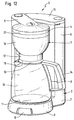
- a filter carrier 1 can be seen in FIGS. 1, 11 and 12, which according to FIG Housing 2 of a coffee machine 3 can be used for domestic needs and by this is worn.
- a brewing head 4 is formed above the filter carrier, which is firmly connected to the housing 2 via a web 5.
- To the side of the Web 5 has a water tank 6 formed on a base 7 of housing 2 sits on. The transition from the base 7 to the water tank 6 is horizontal running dividing line 8 is displayed. From the base 7 extends forward plate-shaped parking foot 9, on the front of a rocker switch or a slide switch 10 is arranged, which is fastened in the support foot 9, but not here electrical switch shown in detail is connected.
- the top of the jack stand 9 is delimited by a warming plate 11 on which a vessel 12, preferably one Glass jug, is turned off.
- the top of the glass jug 12 ends with one on the Glass jug 12 seated lid 13.
- On the outer circumference of the glass jug 12 is a Handle 14 attached, preferably by gluing.
- the inlet pipe via a not line shown in detail is connected to the water tank 6.
- the instantaneous water heater outlet is via a riser pipe, not shown, which is also in the web 5th runs, connected to the brewing head 4.
- the water tank 6 has a cover 15 lockable.
- the filter carrier 1 consists of a preferably Plastic injection molded filter housing 16, which is substantially hemispherical in cross section or ellipsoid. In the lower area is concentric with the filter housing 16 running, a tubular apron 17 attached, with its end face 18 after Fig. 12 ends slightly above the surface of the lid 13. At the lowest point of the ellipsoidal filter housing 16 is a central outlet opening according to Figures 1 and 11 19 formed, which preferably according to FIG. 1 with an annular collar 20 for better Spout of the brewed drinks is provided.
- the apron 17 is used for better thermal insulation of the brewing beverage emerging from the outlet opening 19.
- the brewing head 4 closes the opening 21 of the filter support 1 completely according to FIG Brewing process to avoid heat loss.
- a support ring lies on the edge 22 of the filter housing 16 23, which together with the filter housing 16 forms the actual filter carrier 1.
- the support ring 23 can also be formed in one piece with the filter housing 16.
- FIGS Figures 6 and 7 Another embodiment of a support ring 23 is shown in FIGS Figures 6 and 7 shown.
- the support ring 23 itself or the ring part 36 of the support ring 23 on a support surface 24, which according to Figures 6, 7 and 11 in substantially horizontally and radially outwards, while in Fig. 1 essentially sloping outwards, i.e. conically downwards.
- the contact surface 24 forms a relatively sharp edge 25 (at most very small Radius), from which a transition region 26 adjoins downwards.
- the edge is 25 as well as the bearing surface 24 are annular.
- the wall of the transition area 26 is on the outer envelope 29 of the outer wall 27 of the filter element 28, as shown in Figures 1 to 6, adapted while the wall of the transition area 26 of the support ring 23 according to FIG.
- transition region 30 of the outer wall 27 of the filter element 28 ( Figures 8 to 11) is adapted and is also supported practically over the entire area.
- the transition areas 26, 30 according to FIGS. 1, 2, 3 and 7 show - apart from the paper roughness - a smooth structure, while the transition surfaces 26, 30 according to Figures 11, 8, 9 and 10 have a zigzag structure.
- the support ring 23 consists of a single molded part to which the a lower basket 33 adjoins the lower transition region of the support surface 26, as can be seen from FIGS. 6 and 7.
- the basket 33 consists of Distance from each other downward struts 34, all in one horizontally extending end ring 35, the opening 36 of the filter element 28 is penetrated downward (Fig. 11), so that the filter element 28 in essentially hanging in the filter holder 1.
- the struts 34 essentially follow the envelope curve 29 of the filter element 28, i.e. in the region of the struts 34 and the ring 35 supports the filter element 28 according to FIG. 11 both in radial and in vertical direction partially.
- the main part of the wear is from Margin 39 taken over.
- the basket 33 gives the filter element 1 an additional one secure lateral position in the filter holder 1.
- the support ring 23 is formed in one piece in FIG. 11, the support ring 23 in FIG formed two parts, namely the ellipsoidal section 32, which follows Above a ring part 36 connects.
- the section 32 and the ring member 36 can on the Place 61 glued together, welded, via a thread, by clipping or similar connecting means can be connected to one another.
- the ellipsoid Section 32 is formed according to Fig. 1 by a closed wall 37 which in Distance to the filter housing 16 extends. Due to the double-walled design of the Filter carrier 1, a particularly thermally protected filter carrier unit 1 is created.
- the support ring 23 enables it to be removed Unit without removing the filter holder 1 from the coffee machine 3, but after Fig. 1, the filter element 28 of the closed ellipsoidal section 32 better protected than in the open embodiment according to FIG. 11. According to FIG. 1, this is supported Ring part 36 over the edge 22 on the filter carrier 1.
- FIG. 1 is in the opening 21 of the support ring 23 of the filter carrier 1 used the filter element 28 made of thin filter paper, which in essentially follows the contour of an ellipsoid and at its free end there is a radial one adjoining outwardly extending edge 39, which is advantageously of a ring collar is formed.
- the edge 39 can also consist of individual sections.
- the support surface formed on the underside of the edge 39 of the filter element 28 40 is practically flush with the support surface 24 of the filter support 1, if not the filter element 28 minor deformations due to its proportionality has great flexibility. However, after inserting the filter element 28 can be eliminated by hand pushing into the bottom 62.
- the ring here trained edge 39 of the filter element 28 has - the course at the transition from the Support surface 24 adapted to the transition region 26 of the filter support 1 - a relative sharp corner 41 so that the weight of the filter element 28 better are transferred to the edge 39 and thus a stable position of the filter element 28 in Filter carrier 1 is reached even when wet.
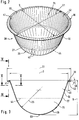
- the filter element 28 consists of overlapping folds 42, which, as clearly shown in particular in Figures 1 and 2, parallel to the longitudinal direction the central axis 43, that is to say radially to the lowest point 63, that on the central axis 43 of the filter element 28 lies, the outer wall 27 of the filter element 28 extend.
- the folds 42 essentially extend in the cross section according to FIGS. 4 and 5 Z-shaped, the top 64 and bottom 65 (Fig. 4) and the outside 66 and the inside 67 (FIG. 5) essentially one above the other in the circumferential direction U (FIG. 4) or next to each other (Fig. 5), so that there is an overlap area 116.
- the folds 42 are not too tight against each other, so that they still form a very small gap, but in extreme cases with very firm pressure in dry state can even be closed.
- the filter element 28 runs in the transition region 30 frustoconical as it passes from the dividing line 44 to runs essentially hemispherical below.
- the truncated cone angle 45 at the transition area 30 is approximately 15 ° with a diameter D in the region of the opening of approx. 115 mm.
- the angle 45 can also be less than 15 °. But he always has to be greater than 0 ° in order to obtain a draft through which the filter element 28 can be removed from the mold at all. The same applies to the Removal from a stack.
- the height H of the filter element 28 is approximately 75 mm. As can be seen from FIG.
- the edge 39 runs outwards and at the same time falling below and enclosing an angle 46 of approximately 5 °.
- Appropriate Dimensions in these areas also apply to the deepest areas 80 of the Contact surface 24 of the V-shaped grooves 79 on the filter carrier 1 according to FIGS. 1, 6, 7, 11 and 12 and for the filter elements 28 according to FIGS. 1, 2, 6, 8, 9, 10 and 11. So that the filter element 28 is always flush with the transition region 26 the diameter D is preferably chosen to be a few millimeters larger. When inserting in The filter element 1 is always the filter element 28 with radial prestress squeezed and does not slip.
- the counter-holding device 38 is a counter-holding device from above onto the opening 21 of the filter carrier 1 38 placed on the top of the edge 39 for holding the filter element 28 rests with its own weight and which over the inner edge 66 of the Filter element 28 centered.
- the counter-holding device 38 can also be removed and inserting the filter element 28 on the filter carrier 1 by means of suitable articulation means (not shown), such as hinges, can be pivoted and can be used to attach the Filter element 28 by means of suitable fastening means, such as clips, snap connections etc., are pressed against the contact surface 24 of the filter carrier 1 or ring part 36.
- suitable fastening means such as clips, snap connections etc.
- a wall 47 protrudes from the left area of the filter carrier 1, which leads to the The holder of the filter carrier 1 in the coffee machine 3 according to FIG. 12 is used.
- the wall 47 goes into the ellipsoidal shape on the circumference of the filter carrier 1 and then runs after Fig. 1 on the right side of the filter carrier 1 according to Fig. 1 ellipsoid.
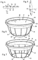
- FIGS. 8 to 11 show a filter element 28 which, in contrast to the Filter element 28 according to Figures 1 to 6 upwards (edge 39) and radially outwards (Transition area 30) has open folds 48.
- Open folds 48 is too understand that - in contrast to the overlapping folds 42 according to FIGS and 5 - do not undercut, i.e. if you look vertically into the recording room from above 76 of the filter element 28 looks as it is shown in FIG visible from above the surface of the filter paper without undercuts.
- the open folds 48 are formed by valley folds 51 and Mountain folds 52 formed.
- the valley and mountain folds are 51, 52 aligned to the lowest point 63.
- an open fold 48 which in cross section in the direction of the central axis 43 from the beginning upward (Fig. 10) is V-shaped expanding and the is limited by the side walls 53, 54.
- Valley folds 51 are to be understood as the folds, the top view of the receiving space 76 as wells or Incisions 71 can be seen.
- the mountain folds 52 start from the Points 69 as a line, which then divide into two folds at points 81. This it is because the paper displacement decreases, i.e. the folds, towards the lowest point 63 51 go into the outer wall 27 of the ellipsoidal section 32 in this area about.
- the mountain fold 52 at the edge 39 becomes a valley fold 51 at point 69 and runs as those up to point 81.
- the envelope curve 29 is defined as an imaginary area that results when one very thin skin over the mountain folds 52 and around the deepest point 63.
- the circumference of the filter element 28 is evenly distributed longer 56 and shorter folds 57 arranged, all directed towards the lowest point 63 are. Between the longer folds 56 there are two shorter folds 57 arranged. The tips 58 of the longer folds 56 lie on a common one according to FIG. 9 Diameter D3 of approximately 37 mm. The top 59 of the shorter ones are also located Folds 57 on a common diameter D4 which is approximately 76 mm.
- one formed at the edge 39 changes Valley fold 51 at the sharp corner 41 to the transition area 30 towards a mountain fold 52, then up to the diameter D3 (long fold 56) or D4 (shorter fold 57) of the ellipsoidal section 32 extends downward.
- the transition from a valley fold 51 to a mountain fold 52 is represented by point 60 during the transition from a mountain fold 52 to a valley fold 51 is represented by point 69.
- the points 60 are on a diameter D of about 110 mm, the points 69, however, are on a diameter D2 of 115 mm.
- a tab 117 projects outwards that serves as a grip element of the filter element 28, so as a filter element 28 better to be able to remove from the stack.
- the flank angle 73 is in a short or longer fold 59, 58 about 67.5 °, this results however, in the number of folds that are even on the circumference of the filter element 28 given diameters D1 and D2 are distributed by themselves, like the fold angle 74 at edge 39.
- the shorter and longer folds 57, 56 both grow in their pleat depth 74 as in their fold width 75 not linear.
- Linearly growing folds are from Pot-shaped filter elements ago known from the prior art, in which the from the circular bottom rising side wall forms a truncated cone.
- the folds 48 must cover the filter material in this way fold away so that on the one hand there is an area in the development, on the other hand in the Filter shape an ellipsoidal or hemispherical shape arises.
- the outer wall 27 of the filter element 28 of the transition region 26 of the support ring 23 is elastically compressed radially inwards, i.e., the valley folds 52 are always at the bottom with a low preload Transition surface 26 of the filter support 1 or the support ring 23, so that the Filter element 28 does not formally fall through opening 21 when inserted, until it finally rests with its edge 39 on the contact surface 24.
- the radial one Constriction on the filter element 28 is from the top and radially outward running, V-shaped valley and mountain folds 51, 52 particularly elastic added so that the filter element 28 very easily with very little force can insert the filter holder 1.
- the filter element 28 still lies with its edge 39 when it is inserted into the filter carrier 1 not evenly on the support surface 24, an operator can again with your hand from above onto the floor 62 in the area of the lowest point 63 Press to properly center the filter element 28 in the filter holder 1 and around the Let the edge 39 rest on the bearing surface 24; and this in particular because the surface of the support surface 24 and the surface of the transition region 30 the same contour as the filter element 28 in the area of the contacting Have surfaces.
- the filter element 28 rotates until the valley folds 51 in the corresponding adapted grooves 79 and elevations 115 engage on the support ring 23 and centered are.
- the elastic behavior of the filter element 28 according to FIG. 2 is not as good as with the filter element 28 according to FIGS. 9 to 11, because here on the filter element overlapping folds and non-open folds 28 are present. However but the rigidity is higher. 1, after inserting the filter element 28 then the ring part 36 from above onto the edge 39 of the filter element set to the edge 39 of the filter element relatively firmly against the bearing surface 24 of the ring member 36 to press.
- ground coffee (not shown) is entered. Then will 12 of the filter carrier 1 brought into the closed position shown there, so that the brewing head 4 closes the opening 21 from above and that of the water heater incoming line (not shown) above the opening 21 of the filter element 28 is located. Now hot water is poured onto the ground coffee or 12 by starting the instantaneous water heater (not shown) by means of the switch 10 hot water via the web 5 and the brewing head 4 into the opening 21 introduced, it penetrates the ground coffee and extracts extraction substances the extraction good.
- the brewed drink produced in this way flows due to the almost the same Distance from the center M (this is about the area on the one hand that results when water runs in and there is a medium liquid level at medium to full Fill level of ground coffee and on the other hand the area of the filter element 28, from which the radial distance to the wall of the filter element 28 is approximately the same is) evenly up to the outer wall 27 of the filter element 28 the outer wall 27 freely from without significant parts of the filter carrier 1 on Drainage to be prevented.
- the struts 34 of the Basket 33 additionally for an even better position of the filter element 28 in the filter carrier 1.
- the struts 34 serve, on the one hand, the filter element 28 to keep radial, on the other hand, this also due to its own weight against falling out secure from the opening 78 of the ring member 36. A support for the filter element 28 alone over the edge 39 is already sufficient.
- the Transition area 26 of the support ring 23 as the bearing surface 24 are designed that they follow the outer contour of the filter element 28, ie with a V-shape Grooves 79 and elevations 115 are provided in the valley folds 51 of the filter element intervention.
- the side walls lie in the wall surfaces of the grooves 79 or elevations 115 53, 54 and are due to the adhesion occurring on these side walls 53, 54 held.
- the brewed drink flows according to Figures 1 and 11 on the outer wall 27 of the Filter element 28 almost uniformly after the extraction substances from the Extraction material from all areas were extracted evenly.
- the brewed drink has reached the lowest point 63 of the filter element 28, it separates from the Filter element 28 and flows into the receiving space 77, from where it is through the opening 19 leaves the filter carrier 1 and flows into a glass can 12 placed underneath.
- the extraction process is finished and the extraction material from the filter element 28 has flowed, the brewing process is finished. Due to the ellipsoidal shape of the filter element 28 a long dripping is avoided, so that after approx. 4 Drain drip the dripping is finished.
- the filter carrier 1 according to FIGS. 1 and 11 can now be removed from the housing 2 can be removed and by tipping the filter carrier 1, the filter element 28 are ejected together with the coffee cake (not shown). It is but also conceivable, only the support ring 23 with the seated filter element 28 by means of a support ring 23, which is not shown in the drawing Remove the handle and remove the filter element 28 by tipping it over (Fig. 11). 1, the counter-holding device 38 has to be folded upwards or otherwise be removed from the ring part 36 or from the filter carrier 1.
- the filter element 28 which is made of very thin filter paper, preferably with a paper thickness of only 0.1 mm, is also the first time in wet condition created a fairly stable filter paper shape, in which without expensive Holding means, the filter element 28 itself is held in the filter carrier 1.
- the stable Filter paper shape allows easy handling and leaves due to the ellipsoid Form excellent brewing results too.
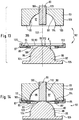
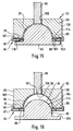
- FIGS. 13 through 17 show the individual method steps for producing a or a plurality of filter elements 28 (FIGS. 1 to 11) with the aid of a tool 92.
- the tool 92 consists of a punch 82, a die 83, a Hold-down 84 and a counter-holder 89 as a fixing means.
- the die 83 has one ellipsoidal cavity 97, the inner wall of which is either smooth or wedge-shaped Incisions 96 is provided.
- a Filter element 28 according to FIGS. 1 to 6 and in the case with wedge-shaped incisions 96 provided inner wall 98 is a filter element shown in Figures 8 to 11 28 manufactured.
- the surface of the stamp 82 must then of course also be used either smooth (filter element 28 according to Figures 1 to 6) or with wedge-shaped elevations 95 (filter element 28 according to Figures 8 to 11) may be provided, which then in the corresponding wedge-shaped incisions 96 can engage in the die 83.
- a bore 100 is formed on the die 83 in the center, which is penetrated by the counter-holder 89 designed as a fixing means.
- the inner surface 101 on the counter-holder 89 forms with the Inner wall 98 of the die 83 an ellipsoidal closed hollow form 97, and this if, for example, the filter element 28 is already fully formed or the Die 83 with the counter-holder 89 moves up again or has moved (FIG. 16).
- the inner surface 101 of the counter-holder 89 is either smooth or wedge-shaped Provide incisions 96 which engage in the elevations 95 of the stamp 82.
- the die 83 is opposite the counter-holder 89 in the longitudinal direction of the central axis 102 slidable.
- the counter-holder 89 is opposite the die 83 in the direction of the Center axis 102 adjustable in height. Also, both counterhold 89 and die 83 can be moved up and down at the same time. 13 closes at the end the inner wall 89 to an annular surface 103, which is also formed with the V-shaped Incisions 96 is provided and which run perpendicular to the central axis 102.
- the matrix 83 and the counterholder are vertical 89 the stamp 82 is formed, which essentially consists of an ellipsoidal hemisphere 104 exists, which runs centrally to the central axis 102.
- the stamp 82 and the die 83 are wedge-shaped elevations 95 which extend so that they in the collapsed state of the punch 82 and the die 83, the incisions 71 in 8 to 10 of the filter element 28 on one side or the incisions 96 fill in the matrix 83 on the other side.
- a ring-shaped shoulder 105 which as Press device against the hold-down 84 is used.
- the tool 92 is extended, i.e. the die 83 with the counter holder 89 run at a distance above the stamp 82, so that between stamp 82 and Matrix 83 with counter-holder 89 creates a free space 106, which allows one Paper disc 93 or a stack 112 of several paper discs 93 from the side by means of a gripping device, not shown, on the top of the outer ring 87 of the hold-down device 84.
- the thickness d should be several represent stacked paper blanks 93.
- the outer ring 87 instructs the hold-down device 84 on its radially outer end an upwardly extending hollow cylindrical wall 107, which, when the outer ring 87 is pressed against the die 83, on the outer wall 108 of the matrix 83 centered.
- This gap 85 can also be vanishingly small, it is only intended to indicate this that the inner ring 86 of this filter paper packet when the filter paper 90 is drawn in 112 not disabled.
- the die 83 and the counter-holder 89 approach each other the stamp 82 and the hold-down 84, it does not matter whether only the Matrix 83 with the counter-holder 89 or only the punch 82 or all parts to each other move.
- the die 83 moves against the outer ring 87 of the hold-down device for so long 84 until the wedge-shaped elevations 95 on the outer ring 87 into the wedge-shaped Slightly engage incisions 96 on the die 83.
- the outer area the paper blanks 93 into slightly V-shaped incisions 71 and roof-shaped elevations 72 preformed.
- the counter-holder 89 then moves against the surface of the filter paper pack 112 and presses the bottom 109 of the last lower paper blank 93, ie the entire filter paper packet 112, with a prestress against the surface 99 of the Stamp 82.
- the paper blanks 93 are opposite the tool 92, as can be seen from FIG. 14, fixed and centered.
- the die 83 moves with the hold-down device 84 against the punch 82 or the punch 82 into the ellipsoidal cavity 97 of the die 83. While at the first variant of the counter-holder 89 is fixed during this shift and the die 83 with its bore 100 according to FIG. 14 on the outer surface 113 of the counter-holder 89 In the second variant, the outer surface 113 slides along the bore 100 along the die 83.
- the filter paper packet 112 lies on the surface 99 of the stamp 82 by in doing so the one from the outer ring 87 against the ring surface 110 of the die 83 slightly pressed area of the filter paper packet 112 slides radially inwards and in the filter element 28, the valley folds 51 and mountain folds 52 according to FIGS. 8 to 10 through the die 83 and the hold-down 84 are introduced.
- the presses outer ring 87 just so tight against the filter paper packet 112 that it always has sufficient tension to form the folds 51, 52 and at the same time nevertheless the radially outer edge of the filter paper packet 112 slides inward out of the gap 85.
- the inner ring 86 lies only slightly on the underside 109 of the filter paper packet 112.
- the filter paper package 112 is thus drawn according to the invention over the corner region 114, wherein at the same time the valley folds 51 and mountain folds 52 according to FIGS. 8 to 10 through the Die 83 and the hold-down 84 are molded. This is how it works long until the position shown in Fig. 15 is reached, i.e. the punch 82 is now completely retracted into the cavity 97. While the wedge-shaped elevations 95 engage in the wedge-shaped cuts 96, the filter paper packet 112 will be in its final shape, even on the inner area that does not have the corner area 114 slides, pressed.
- the punch 82 is pressed so firmly against the die 83 and the counter-holder 89, that the filter paper packet 112 receives its final shape according to FIGS. 8 to 10.
- this pressing process only the valley or mountain folds 51, 52 are pressed, but not the side walls 53, 54 of Fig. 10. This is due to the appropriate training the incisions 96 and elevations 95 reached in the tool 92.
- the molding process is based on a predetermined one Hold time ended.
- the die 83 with the counter-holder 89 now moves upward out of the stamp 82 out, although the inner ring 86 still presses firmly against the edge 39.
- the hold-down device 84 also moves away from the die 83, so that the filter paper package 112 only by its radial preload, which against the inner wall 89 of the Matrix 83 acts in which matrix 83 is held.
- a suction device (not shown) on the counter-holder 89 to attach, through which the filter paper packet 112 is firmly against the counter-holder 89.
- the filter paper packet should pass through a vacuum device (not shown) formed in the counter holder 89 will.
- a counterpressure device (not shown), which engages in the receiving space 76 and at the same time the bottom 62 against the inner surface 101 of the counter holder 89 presses the filter paper packet 112 on the counter holder 89 to keep.
- the finished filter paper packet 112 removed from the tool 92 and inserted in a packaging adapted to the filter paper packet 112.
Landscapes
- Engineering & Computer Science (AREA)
- Food Science & Technology (AREA)
- Apparatus For Making Beverages (AREA)
- Ceramic Capacitors (AREA)
- Piezo-Electric Or Mechanical Vibrators, Or Delay Or Filter Circuits (AREA)
- Filtration Of Liquid (AREA)
- Separation Using Semi-Permeable Membranes (AREA)
Priority Applications (9)
| Application Number | Priority Date | Filing Date | Title |
|---|---|---|---|
| AT97104260T ATE179314T1 (de) | 1997-03-13 | 1997-03-13 | Filtriervorrichtung, filterelement und verfahren zur herstellung des filterelements, das zum herstellen von brühgetränken dient |
| DE59700148T DE59700148D1 (de) | 1997-03-13 | 1997-03-13 | Filtriervorrichtung, Filterelement und Verfahren zur Herstellung des Filterelements, das zum Herstellen von Brühgetränken dient |
| EP97104260A EP0865749B1 (fr) | 1997-03-13 | 1997-03-13 | Dispositif pour filtrer, élément de filtration et méthode pour fabriquer une élément de filtration utilisé pour faire des boissons infusées |
| ES97104260T ES2134040T3 (es) | 1997-03-13 | 1997-03-13 | Dispositivo de filtracion, elemento de filtro y metodo para la fabricacion del elemento de filtro que sirve para obtener las bebidas calientes. |
| DK97104260T DK0865749T3 (da) | 1997-03-13 | 1997-03-13 | Filtreringsindretning, filterelement og fremgangsmåde til fremstilling af filterelementet, som tjener til at fremstille var |
| CA002284092A CA2284092A1 (fr) | 1997-03-13 | 1998-02-16 | Dispositif de filtrage, element de filtrage utile pour preparer des infusions, et procede de fabrication de l'element de filtrage |
| AU63990/98A AU6399098A (en) | 1997-03-13 | 1998-02-16 | Filtering device, filter element for preparing brewed beverages, and process forproducing the filter element |
| PCT/EP1998/000864 WO1998039997A1 (fr) | 1997-03-13 | 1998-02-16 | Dispositif de filtrage, element de filtrage utile pour preparer des infusions, et procede de fabrication de l'element de filtrage |
| US09/382,751 US6189438B1 (en) | 1997-03-13 | 1999-08-25 | Filtering device, filter element and method of manufacturing the filter element used for the preparation of brewed beverages |
Applications Claiming Priority (2)
| Application Number | Priority Date | Filing Date | Title |
|---|---|---|---|
| EP97104260A EP0865749B1 (fr) | 1997-03-13 | 1997-03-13 | Dispositif pour filtrer, élément de filtration et méthode pour fabriquer une élément de filtration utilisé pour faire des boissons infusées |
| PCT/EP1998/000864 WO1998039997A1 (fr) | 1997-03-13 | 1998-02-16 | Dispositif de filtrage, element de filtrage utile pour preparer des infusions, et procede de fabrication de l'element de filtrage |
Publications (2)
| Publication Number | Publication Date |
|---|---|
| EP0865749A1 true EP0865749A1 (fr) | 1998-09-23 |
| EP0865749B1 EP0865749B1 (fr) | 1999-04-28 |
Family
ID=26070272
Family Applications (1)
| Application Number | Title | Priority Date | Filing Date |
|---|---|---|---|
| EP97104260A Expired - Lifetime EP0865749B1 (fr) | 1997-03-13 | 1997-03-13 | Dispositif pour filtrer, élément de filtration et méthode pour fabriquer une élément de filtration utilisé pour faire des boissons infusées |
Country Status (9)
| Country | Link |
|---|---|
| US (1) | US6189438B1 (fr) |
| EP (1) | EP0865749B1 (fr) |
| AT (1) | ATE179314T1 (fr) |
| AU (1) | AU6399098A (fr) |
| CA (1) | CA2284092A1 (fr) |
| DE (1) | DE59700148D1 (fr) |
| DK (1) | DK0865749T3 (fr) |
| ES (1) | ES2134040T3 (fr) |
| WO (1) | WO1998039997A1 (fr) |
Cited By (7)
| Publication number | Priority date | Publication date | Assignee | Title |
|---|---|---|---|---|
| EP1167204A1 (fr) * | 2000-06-20 | 2002-01-02 | Keurig, Incorporated. | Procédé pour fabriquer et introduire des éléments filtrants dans des récipients en forme de gobelet |
| US8906440B2 (en) | 2011-06-16 | 2014-12-09 | Javajig, Llc | Coffee filter basket |
| US10737876B2 (en) | 2015-07-13 | 2020-08-11 | K-Fee System Gmbh | Filter element having a cut-out |
| US11045035B2 (en) | 2015-09-18 | 2021-06-29 | K-Fee System Gmbh | Adapter for a single serve capsule |
| US11084650B2 (en) | 2015-06-10 | 2021-08-10 | K-Fee System Gmbh | Portion capsule with a three-ply nonwoven fabric |
| US12227323B2 (en) | 2018-07-27 | 2025-02-18 | Gcs German Capsule Solution Gmbh | Method for producing a portion capsule |
| US12459728B2 (en) | 2018-11-22 | 2025-11-04 | Gcs German Capsule Solution Gmbh | Seal for a single serve capsule |
Families Citing this family (88)
| Publication number | Priority date | Publication date | Assignee | Title |
|---|---|---|---|---|
| US6658989B2 (en) * | 2001-04-11 | 2003-12-09 | Keurig, Incorporated | Re-usable beverage filter cartridge |
| CA2421128C (fr) * | 2002-03-14 | 2008-05-20 | 1693778 Ontario Limited | Cartouche et filtre a boissons |
| AUPS284702A0 (en) * | 2002-06-07 | 2002-06-27 | University Of Technology, Sydney | Novel screens to identify agents that modulate pericyte function and diagnostic and therapeutic applications therefor |
| US20040265436A1 (en) * | 2002-07-06 | 2004-12-30 | Cai Edward Z | Coffee filter paper and method of use |
| US7318374B2 (en) * | 2003-01-21 | 2008-01-15 | Victor Guerrero | Wire cloth coffee filtering systems |
| US20050051478A1 (en) * | 2003-09-10 | 2005-03-10 | Basil Karanikos | Beverage filter cartridge |
| US7461587B2 (en) * | 2004-01-21 | 2008-12-09 | Victor Guerrero | Beverage container with wire cloth filter |
| US20050223903A1 (en) * | 2004-04-07 | 2005-10-13 | Mcdaniel Richard I | Coffee filter ring |
| US8062683B2 (en) * | 2004-05-05 | 2011-11-22 | Columbus E. Aps | Disposable brewing device |
| WO2005117670A2 (fr) * | 2004-05-28 | 2005-12-15 | Bunn-O-Matic Corporation | Support de substance a insert amovible |
| US20060021930A1 (en) * | 2004-07-30 | 2006-02-02 | Cai Edward Z | Coffee paper filters and method of use |
| US9795243B2 (en) * | 2005-05-23 | 2017-10-24 | Adrian Rivera | Single serving brewing material holder |
| US9844292B2 (en) * | 2009-10-30 | 2017-12-19 | Adrian Rivera | Coffee maker with multi and single cup modes |
| US7685931B2 (en) | 2005-05-23 | 2010-03-30 | Adrian Rivera | Systems and methods for forming pre-packaged brewing material |
| US11369226B2 (en) * | 2005-05-23 | 2022-06-28 | Adrian Rivera | Beverage brewing material support |
| US8621981B2 (en) * | 2009-10-30 | 2014-01-07 | Adrian Rivera | Coffee maker |
| JP2008545496A (ja) * | 2005-06-08 | 2008-12-18 | ジーンズ ディフュージョン | 人工膣に適合可能な動物精液の収集のための装置 |
| CN200984099Y (zh) * | 2005-12-21 | 2007-12-05 | 皇家飞利浦电子股份有限公司 | 制备饮料的筒,饮料制备机和饮料制备系统 |
| CN101360439B (zh) * | 2006-01-20 | 2012-02-22 | Pi-设计公开股份公司 | 滤芯 |
| AT503943B1 (de) * | 2006-09-08 | 2008-02-15 | Bernd Mag Litzka | Topfförmiger, oben offener behälter |
| US11832755B2 (en) * | 2007-07-13 | 2023-12-05 | Adrian Rivera | Brewing material container for a beverage brewer |
| US9572452B2 (en) | 2010-12-04 | 2017-02-21 | Adrian Rivera | Single serving brewing material adapter with readable label |
| US9907425B2 (en) | 2007-07-13 | 2018-03-06 | Adrian Rivera | Reusable brewing cartridge |
| US10722066B2 (en) * | 2010-12-04 | 2020-07-28 | Adrian Rivera | Windowed single serving brewing material holder |
| US11337543B2 (en) * | 2007-07-13 | 2022-05-24 | Adrian Rivera | Brewing material holder |
| US12342955B2 (en) | 2020-10-30 | 2025-07-01 | Adrian Rivera Maynez Enterprises, Inc. | Brewing material container for a beverage brewer |
| US10258186B2 (en) | 2013-02-01 | 2019-04-16 | Adrian Rivera | Brewing cartridge |
| US9242790B2 (en) | 2007-07-13 | 2016-01-26 | Adrian Rivera | Method for tamping brewing material using a self tamping single serving brewing material holder |
| US8967038B2 (en) | 2007-07-13 | 2015-03-03 | Adrian Rivera | Cartridge for use in coffee maker |
| US9232871B2 (en) * | 2007-07-13 | 2016-01-12 | ARM Enterprises | Single serving reusable brewing material holder with offset passage for offset bottom needle |
| US12396588B2 (en) | 2007-07-13 | 2025-08-26 | Adrian Rivera Maynez Enterprises, Inc. | Brewing material container for a beverage brewer |
| US9179797B2 (en) | 2007-07-13 | 2015-11-10 | Adrian Rivera | Disposable single serving beverage pod adapter |
| US10865039B2 (en) * | 2010-12-04 | 2020-12-15 | Adrian Rivera | Single serving brewing material holder |
| ITBO20100219A1 (it) * | 2010-04-09 | 2011-10-10 | Gino Rapparini | Perfezionamenti ad un contenitore permeabile filtrante ottenuto per termoformatura partendo da nastro di materiale piano , contenente prodotti idrosolubili o da infusione atti ad ottenere bevande |
| US11464357B2 (en) | 2009-10-30 | 2022-10-11 | Adrian Rivera | Beverage brewer with multi- and single-cup modes |
| US9113747B2 (en) | 2009-10-30 | 2015-08-25 | Adrian Rivera | Single and multi-cup coffee maker |
| US10251509B2 (en) | 2009-10-30 | 2019-04-09 | Adrian Rivera | Coffee maker with multi and single cup modes |
| IT1399364B1 (it) * | 2010-04-07 | 2013-04-16 | Technology For Beverage Srl | Capsula monouso per la produzione di una bevanda aromatica, procedimento e macchina di processo per la sua realizzazione |
| KR200450676Y1 (ko) * | 2010-06-22 | 2010-10-21 | 컨벡스코리아(주) | 커피 캡슐용 리셉터클 |
| US10071851B2 (en) | 2010-07-12 | 2018-09-11 | Robert Bao Vu | Apparatus and products for producing beverages, and methods for making and using same |
| DK3521210T3 (da) * | 2010-07-22 | 2020-04-14 | K Fee System Gmbh | Portionskapsel med stregkode |
| BR112013011242A2 (pt) * | 2010-11-11 | 2016-11-01 | Nestec S A Ch | cápsula, máquina de produção de bebidas e sistema para a preparação de um produto nutricional |
| US12582258B2 (en) * | 2010-12-04 | 2026-03-24 | Adrian Rivera Maynez Enterprises, Inc. | Beverage brewing material filter cup |
| US9039589B2 (en) | 2011-01-22 | 2015-05-26 | Adrian Rivera | Beverage pod packaging manufacturing machine |
| US8875477B2 (en) | 2011-01-22 | 2014-11-04 | Adrian Rivera | Beverage pod manufacturing machine |
| GB2488799A (en) | 2011-03-08 | 2012-09-12 | Kraft Foods R & D Inc | Drinks Pod without Piercing of Outer Shell |
| USD694620S1 (en) | 2011-03-08 | 2013-12-03 | Kraft Foods R&D, Inc. | Beverage cartridge |
| US9114902B2 (en) | 2011-03-22 | 2015-08-25 | Polyone Designed Structures And Solutions Llc | Methods and systems for use in forming an article from a multi-layer sheet structure |
| GB2489409B (en) | 2011-03-23 | 2013-05-15 | Kraft Foods R & D Inc | A capsule and a system for, and a method of, preparing a beverage |
| US9510705B2 (en) * | 2011-04-13 | 2016-12-06 | Patrick J. Rolfes | Pre-packaged beverage brewer press |
| US8707855B2 (en) | 2011-05-09 | 2014-04-29 | Eko Brands, Llc | Beverage Brewing Device |
| CA2788283C (fr) | 2011-09-01 | 2019-11-26 | 2266170 Ontario Inc. | Capsule de contenant de boisson |
| ITMI20111753A1 (it) | 2011-09-29 | 2013-03-30 | Novacart Spa | Capsula in materiale cartaceo |
| ITVR20120093A1 (it) * | 2012-05-15 | 2013-11-16 | Coffee Star S A | Sistema per la produzione di bevanade |
| JP2013248069A (ja) * | 2012-05-31 | 2013-12-12 | Agc Techno Glass Co Ltd | ドリッパー |
| DE102012105282A1 (de) * | 2012-06-18 | 2013-12-19 | K-Fee System Gmbh | Portionskapsel und Verfahren zur Herstellung eines Getränks mit einer Portionskapsel |
| KR102075814B1 (ko) | 2012-06-22 | 2020-02-10 | 터치 커피 & 베버리지스, 엘엘씨. | 음료 브루잉 시스템 |
| USD708057S1 (en) | 2012-09-10 | 2014-07-01 | Kraft Foods R & D, Inc. | Beverage cartridge |
| USD697797S1 (en) | 2012-09-12 | 2014-01-21 | Kraft Foods R&D, Inc. | Beverage cartridge |
| US10450130B2 (en) | 2012-09-12 | 2019-10-22 | Kraft Foods R & D, Inc. | Cartridges, systems and methods for preparation of beverages |
| CA2832794C (fr) * | 2012-11-07 | 2016-03-22 | 2266170 Ontario Inc. | Capsule de boisson a filtre moulable |
| US9688465B2 (en) | 2012-11-12 | 2017-06-27 | 2266170 Ontario Inc. | Beverage capsule and process and system for making same |
| US11013364B2 (en) | 2013-02-01 | 2021-05-25 | Adrian Rivera | Brewing cartridge adapter |
| US12185866B2 (en) | 2013-02-01 | 2025-01-07 | Adrian Rivera | Brewing cartridge adapter |
| WO2014161089A1 (fr) | 2013-04-03 | 2014-10-09 | 2266170 Ontario Inc. | Machine à dosettes et composants |
| CA2912723C (fr) | 2013-05-23 | 2017-02-07 | 2266170 Ontario Inc. | Logement de capsule |
| CA2922822C (fr) | 2013-08-20 | 2021-01-12 | 2266170 Ontario Inc. | Capsule avec element de commande |
| US10314319B2 (en) * | 2013-11-20 | 2019-06-11 | 2266170 Ontario Inc. | Method and apparatus for accelerated or controlled degassing of roasted coffee |
| US10604420B2 (en) | 2013-12-18 | 2020-03-31 | Brita Lp | Method and apparatus for reservoir free and ventless water filtering |
| US20150257586A1 (en) * | 2014-03-11 | 2015-09-17 | Starbucks Corporation Dba Starbucks Coffee Company | Single-serve beverage production machine |
| WO2015139140A1 (fr) | 2014-03-21 | 2015-09-24 | 2266170 Ontario Inc. | Capsule avec chambre de trempage |
| CA2948172A1 (fr) * | 2014-05-13 | 2015-11-19 | Cool Gear International, Llc | Ensemble filtre a eau pour infusion d'aromes |
| USD757536S1 (en) | 2014-10-01 | 2016-05-31 | Kraft Foods Group Brands Llc | Container |
| CN107074440A (zh) | 2014-10-01 | 2017-08-18 | 卡夫食品集团品牌有限责任公司 | 咖啡囊包 |
| US9439531B1 (en) * | 2015-06-15 | 2016-09-13 | Alan J. Bornt | Method of using a portable beverage brewing machine |
| FI3310693T4 (fi) * | 2015-06-16 | 2023-03-28 | Annoskapseli ja menetelmä juoman valmistamiseksi annoskapselilla | |
| WO2017042756A1 (fr) * | 2016-07-27 | 2017-03-16 | Universidad Tecnológica De Panamá | Contenant d'isolation thermique |
| US10569201B2 (en) | 2017-06-15 | 2020-02-25 | Jordacon Enterprises Llc | Filter device and method |
| TWI721240B (zh) * | 2018-01-08 | 2021-03-11 | 林紫綺 | 掛耳式杯套結構 |
| WO2020112536A1 (fr) * | 2018-11-28 | 2020-06-04 | Cummins Filtration Ip, Inc. | Joint incurvé sur élément filtrant et moule de joint de protection |
| US12193598B2 (en) | 2019-04-08 | 2025-01-14 | Adrian Rivera | Beverage brewer with multi- and single-cup modes |
| USD927250S1 (en) | 2020-03-23 | 2021-08-10 | Eko Brands, Llc | Reusable filter cartridge |
| US11825979B2 (en) * | 2020-08-20 | 2023-11-28 | Savepods Inc. | Single serve systems, apparatuses, and methods |
| US11805934B1 (en) * | 2020-10-21 | 2023-11-07 | Adrian Rivera | Brewing material lid and container for a beverage brewer |
| US20250098889A1 (en) * | 2020-11-25 | 2025-03-27 | Adrian Rivera | Beverage Brewing Material Filter Cup |
| USD1055632S1 (en) | 2021-02-26 | 2024-12-31 | Universal Coffee LLC | Reusable filter cartridge |
| CN119012946A (zh) * | 2022-02-22 | 2024-11-22 | 巴德尔格·卡斯 | 饮料过滤器 |
| CN115125674B (zh) * | 2022-07-22 | 2023-08-29 | 广东鑫球新材料科技有限公司 | 一种内插接式空芯棉模具及成型方法 |
Citations (6)
| Publication number | Priority date | Publication date | Assignee | Title |
|---|---|---|---|---|
| US1615542A (en) * | 1926-02-26 | 1927-01-25 | Edward P Gros | Coffee percolator |
| US2546874A (en) * | 1947-06-18 | 1951-03-27 | Nelson J Siegrist | Lining for coffee-making instrumentalities |
| EP0253246A2 (fr) * | 1986-07-16 | 1988-01-20 | Erich H. Woltermann | Filtre à faire bouillir du café ou du thé par portions |
| US4735719A (en) * | 1987-02-12 | 1988-04-05 | Benedict Engineering Co., Inc. | Coffee filter ring |
| DE4038023A1 (de) * | 1990-11-29 | 1992-06-04 | Markhorst Holland | Verfahren zur herstellung eines zwei- oder mehrschalenbehaelters aus pappe oder einem aehnlichen werkstoff |
| EP0741988A1 (fr) * | 1994-12-14 | 1996-11-13 | Kabushiki Kaisha Tokiwa Kogyo | Filtre |
Family Cites Families (4)
| Publication number | Priority date | Publication date | Assignee | Title |
|---|---|---|---|---|
| US3089405A (en) | 1962-01-26 | 1963-05-14 | Lionel D Ackerman | Coffee brewing element |
| DE3016729A1 (de) * | 1980-04-30 | 1981-11-05 | Maxs Ag, Sachseln | Korbfilter |
| US5171457A (en) * | 1991-07-10 | 1992-12-15 | Pamela A. Acuff | Method of handling wet coffee grounds in filter cups |
| ES1021256Y (es) * | 1992-05-12 | 1993-03-16 | Penalba Corpas Miguel Angel | Filtro dosificador para cafeteras express industriales o domesticas. |
-
1997
- 1997-03-13 DK DK97104260T patent/DK0865749T3/da active
- 1997-03-13 ES ES97104260T patent/ES2134040T3/es not_active Expired - Lifetime
- 1997-03-13 AT AT97104260T patent/ATE179314T1/de not_active IP Right Cessation
- 1997-03-13 EP EP97104260A patent/EP0865749B1/fr not_active Expired - Lifetime
- 1997-03-13 DE DE59700148T patent/DE59700148D1/de not_active Expired - Fee Related
-
1998
- 1998-02-16 AU AU63990/98A patent/AU6399098A/en not_active Abandoned
- 1998-02-16 CA CA002284092A patent/CA2284092A1/fr not_active Abandoned
- 1998-02-16 WO PCT/EP1998/000864 patent/WO1998039997A1/fr not_active Ceased
-
1999
- 1999-08-25 US US09/382,751 patent/US6189438B1/en not_active Expired - Fee Related
Patent Citations (6)
| Publication number | Priority date | Publication date | Assignee | Title |
|---|---|---|---|---|
| US1615542A (en) * | 1926-02-26 | 1927-01-25 | Edward P Gros | Coffee percolator |
| US2546874A (en) * | 1947-06-18 | 1951-03-27 | Nelson J Siegrist | Lining for coffee-making instrumentalities |
| EP0253246A2 (fr) * | 1986-07-16 | 1988-01-20 | Erich H. Woltermann | Filtre à faire bouillir du café ou du thé par portions |
| US4735719A (en) * | 1987-02-12 | 1988-04-05 | Benedict Engineering Co., Inc. | Coffee filter ring |
| DE4038023A1 (de) * | 1990-11-29 | 1992-06-04 | Markhorst Holland | Verfahren zur herstellung eines zwei- oder mehrschalenbehaelters aus pappe oder einem aehnlichen werkstoff |
| EP0741988A1 (fr) * | 1994-12-14 | 1996-11-13 | Kabushiki Kaisha Tokiwa Kogyo | Filtre |
Cited By (9)
| Publication number | Priority date | Publication date | Assignee | Title |
|---|---|---|---|---|
| EP1167204A1 (fr) * | 2000-06-20 | 2002-01-02 | Keurig, Incorporated. | Procédé pour fabriquer et introduire des éléments filtrants dans des récipients en forme de gobelet |
| US6440256B1 (en) | 2000-06-20 | 2002-08-27 | Keurig, Incorporated | Method of forming and inserting filter elements in cup-shaped containers |
| US8906440B2 (en) | 2011-06-16 | 2014-12-09 | Javajig, Llc | Coffee filter basket |
| US11084650B2 (en) | 2015-06-10 | 2021-08-10 | K-Fee System Gmbh | Portion capsule with a three-ply nonwoven fabric |
| US10737876B2 (en) | 2015-07-13 | 2020-08-11 | K-Fee System Gmbh | Filter element having a cut-out |
| US11498750B2 (en) | 2015-07-13 | 2022-11-15 | Gcs German Capsule Solution Gmbh | Filter element having a cut-out |
| US11045035B2 (en) | 2015-09-18 | 2021-06-29 | K-Fee System Gmbh | Adapter for a single serve capsule |
| US12227323B2 (en) | 2018-07-27 | 2025-02-18 | Gcs German Capsule Solution Gmbh | Method for producing a portion capsule |
| US12459728B2 (en) | 2018-11-22 | 2025-11-04 | Gcs German Capsule Solution Gmbh | Seal for a single serve capsule |
Also Published As
| Publication number | Publication date |
|---|---|
| EP0865749B1 (fr) | 1999-04-28 |
| AU6399098A (en) | 1998-09-29 |
| ES2134040T3 (es) | 1999-09-16 |
| CA2284092A1 (fr) | 1998-09-17 |
| DK0865749T3 (da) | 1999-11-15 |
| WO1998039997A1 (fr) | 1998-09-17 |
| US6189438B1 (en) | 2001-02-20 |
| DE59700148D1 (de) | 1999-06-02 |
| ATE179314T1 (de) | 1999-05-15 |
Similar Documents
| Publication | Publication Date | Title |
|---|---|---|
| EP0865749B1 (fr) | Dispositif pour filtrer, élément de filtration et méthode pour fabriquer une élément de filtration utilisé pour faire des boissons infusées | |
| DE69321209T2 (de) | Verfahren und vorrichtung zur extraktion undurchlässiger, verformbarer portionspackungen | |
| DE19711025C1 (de) | Espressobrühkopfeinheit | |
| EP0876121B1 (fr) | Systeme de filtration | |
| DE69205232T2 (de) | Flexible Kaffeekassette mit einem versteifenden Element und Verfahren zu ihrer Herstellung. | |
| EP2682028B1 (fr) | Insert pour une machine à café à dosettes | |
| DE69201237T2 (de) | Filtereinsatz für behälter. | |
| EP2342997B1 (fr) | Machine de préparation de boissons | |
| DE102004056224A1 (de) | System mit einer Kaffeemaschine und einer Portionskapsel | |
| DE102005058336A1 (de) | Portionskapsel | |
| DE29818306U1 (de) | Aufgußvorrichtung für Getränke | |
| DE60110203T2 (de) | Filtriervorrichtung für Kaffee oder dergleichen | |
| DE2100812A1 (de) | Filter | |
| DE3432339C2 (fr) | ||
| EP3743358B1 (fr) | Emballage pour une portion et procédé pour la production d'une boisson | |
| EP0893960B1 (fr) | Machine a cafe et element-filtre approprie | |
| WO1996004829A1 (fr) | Filtre a the pour machine a preparer du cafe ou du the | |
| EP0249700A2 (fr) | Machine pour faire une infusion de café | |
| DE202010007854U1 (de) | Teebeutelhalter | |
| DE69513953T2 (de) | Einwegfilterbeutel zur herstellung von aufgussgetränken wie tee | |
| DE60101558T2 (de) | Mit einem träger ausgestatteter extraktionsbeutel, extraktionsobjekt-material welches einen mit einem träger ausgestatteten extraktionsbeutel enthält und verbundwerkstoff zu seiner herstellung | |
| EP1502526B1 (fr) | Couvercle distributeur pour bac à mouture | |
| EP0967905A1 (fr) | Dispositif filtrant, element filtrant et procede de fabrication de l'element filtrant servant a la preparation de boissons infusees | |
| DE3613119A1 (de) | Kaffeemaschine zur herstellung von kaffeesud | |
| EP0861679A1 (fr) | Procédé et appareil pour le traitement des cendres |
Legal Events
| Date | Code | Title | Description |
|---|---|---|---|
| GRAG | Despatch of communication of intention to grant |
Free format text: ORIGINAL CODE: EPIDOS AGRA |
|
| PUAI | Public reference made under article 153(3) epc to a published international application that has entered the european phase |
Free format text: ORIGINAL CODE: 0009012 |
|
| GRAG | Despatch of communication of intention to grant |
Free format text: ORIGINAL CODE: EPIDOS AGRA |
|
| GRAG | Despatch of communication of intention to grant |
Free format text: ORIGINAL CODE: EPIDOS AGRA |
|
| GRAH | Despatch of communication of intention to grant a patent |
Free format text: ORIGINAL CODE: EPIDOS IGRA |
|
| 17P | Request for examination filed |
Effective date: 19970909 |
|
| AK | Designated contracting states |
Kind code of ref document: A1 Designated state(s): AT BE CH DE DK ES FI FR GB GR IE IT LI LU MC NL PT SE |
|
| GRAH | Despatch of communication of intention to grant a patent |
Free format text: ORIGINAL CODE: EPIDOS IGRA |
|
| GRAA | (expected) grant |
Free format text: ORIGINAL CODE: 0009210 |
|
| AK | Designated contracting states |
Kind code of ref document: B1 Designated state(s): AT BE CH DE DK ES FI FR GB GR IE IT LI LU MC NL PT SE |
|
| PG25 | Lapsed in a contracting state [announced via postgrant information from national office to epo] |
Ref country code: GR Free format text: LAPSE BECAUSE OF NON-PAYMENT OF DUE FEES Effective date: 19990428 |
|
| REF | Corresponds to: |
Ref document number: 179314 Country of ref document: AT Date of ref document: 19990515 Kind code of ref document: T |
|
| REG | Reference to a national code |
Ref country code: CH Ref legal event code: NV Representative=s name: LUCHS & PARTNER PATENTANWAELTE Ref country code: CH Ref legal event code: EP |
|
| GBT | Gb: translation of ep patent filed (gb section 77(6)(a)/1977) |
Effective date: 19990428 |
|
| REG | Reference to a national code |
Ref country code: IE Ref legal event code: FG4D Free format text: GERMAN |
|
| AKX | Designation fees paid |
Free format text: AT BE CH DE DK ES FI FR GB GR IE IT LI LU MC NL PT SE |
|
| RBV | Designated contracting states (corrected) |
Designated state(s): AT BE CH DE DK ES FI FR GB GR IE IT LI LU MC NL PT SE |
|
| REF | Corresponds to: |
Ref document number: 59700148 Country of ref document: DE Date of ref document: 19990602 |
|
| ET | Fr: translation filed | ||
| PG25 | Lapsed in a contracting state [announced via postgrant information from national office to epo] |
Ref country code: PT Free format text: LAPSE BECAUSE OF FAILURE TO SUBMIT A TRANSLATION OF THE DESCRIPTION OR TO PAY THE FEE WITHIN THE PRESCRIBED TIME-LIMIT Effective date: 19990730 |
|
| REG | Reference to a national code |
Ref country code: ES Ref legal event code: FG2A Ref document number: 2134040 Country of ref document: ES Kind code of ref document: T3 |
|
| REG | Reference to a national code |
Ref country code: DK Ref legal event code: T3 |
|
| RAP2 | Party data changed (patent owner data changed or rights of a patent transferred) |
Owner name: BRAUN GMBH |
|
| NLT2 | Nl: modifications (of names), taken from the european patent patent bulletin |
Owner name: BRAUN GMBH |
|
| PLBE | No opposition filed within time limit |
Free format text: ORIGINAL CODE: 0009261 |
|
| STAA | Information on the status of an ep patent application or granted ep patent |
Free format text: STATUS: NO OPPOSITION FILED WITHIN TIME LIMIT |
|
| PG25 | Lapsed in a contracting state [announced via postgrant information from national office to epo] |
Ref country code: LU Free format text: LAPSE BECAUSE OF NON-PAYMENT OF DUE FEES Effective date: 20000313 |
|
| PGFP | Annual fee paid to national office [announced via postgrant information from national office to epo] |
Ref country code: ES Payment date: 20000315 Year of fee payment: 4 |
|
| PGFP | Annual fee paid to national office [announced via postgrant information from national office to epo] |
Ref country code: AT Payment date: 20000320 Year of fee payment: 4 |
|
| PGFP | Annual fee paid to national office [announced via postgrant information from national office to epo] |
Ref country code: FI Payment date: 20000321 Year of fee payment: 4 Ref country code: BE Payment date: 20000321 Year of fee payment: 4 |
|
| PGFP | Annual fee paid to national office [announced via postgrant information from national office to epo] |
Ref country code: DK Payment date: 20000322 Year of fee payment: 4 |
|
| PGFP | Annual fee paid to national office [announced via postgrant information from national office to epo] |
Ref country code: SE Payment date: 20000323 Year of fee payment: 4 |
|
| 26N | No opposition filed | ||
| REG | Reference to a national code |
Ref country code: FR Ref legal event code: CD Ref country code: FR Ref legal event code: CA |
|
| PG25 | Lapsed in a contracting state [announced via postgrant information from national office to epo] |
Ref country code: IE Free format text: LAPSE BECAUSE OF NON-PAYMENT OF DUE FEES Effective date: 20000719 |
|
| REG | Reference to a national code |
Ref country code: IE Ref legal event code: FD4D |
|
| REG | Reference to a national code |
Ref country code: CH Ref legal event code: PFA Free format text: BRAUN AKTIENGESELLSCHAFT TRANSFER- BRAUN AKTIENGESELLSCHAFT;BRAUN GMBH |
|
| PG25 | Lapsed in a contracting state [announced via postgrant information from national office to epo] |
Ref country code: MC Free format text: LAPSE BECAUSE OF NON-PAYMENT OF DUE FEES Effective date: 20000930 |
|
| PG25 | Lapsed in a contracting state [announced via postgrant information from national office to epo] |
Ref country code: FI Free format text: LAPSE BECAUSE OF NON-PAYMENT OF DUE FEES Effective date: 20010313 Ref country code: DK Free format text: LAPSE BECAUSE OF NON-PAYMENT OF DUE FEES Effective date: 20010313 Ref country code: AT Free format text: LAPSE BECAUSE OF NON-PAYMENT OF DUE FEES Effective date: 20010313 |
|
| PG25 | Lapsed in a contracting state [announced via postgrant information from national office to epo] |
Ref country code: SE Free format text: LAPSE BECAUSE OF NON-PAYMENT OF DUE FEES Effective date: 20010314 Ref country code: ES Free format text: LAPSE BECAUSE OF NON-PAYMENT OF DUE FEES Effective date: 20010314 |
|
| PG25 | Lapsed in a contracting state [announced via postgrant information from national office to epo] |
Ref country code: LI Free format text: LAPSE BECAUSE OF NON-PAYMENT OF DUE FEES Effective date: 20010331 Ref country code: CH Free format text: LAPSE BECAUSE OF NON-PAYMENT OF DUE FEES Effective date: 20010331 Ref country code: BE Free format text: LAPSE BECAUSE OF NON-PAYMENT OF DUE FEES Effective date: 20010331 |
|
| BERE | Be: lapsed |
Owner name: BRAUN A.G. Effective date: 20010331 |
|
| PG25 | Lapsed in a contracting state [announced via postgrant information from national office to epo] |
Ref country code: NL Free format text: LAPSE BECAUSE OF NON-PAYMENT OF DUE FEES Effective date: 20011001 |
|
| EUG | Se: european patent has lapsed |
Ref document number: 97104260.1 |
|
| REG | Reference to a national code |
Ref country code: CH Ref legal event code: PL |
|
| REG | Reference to a national code |
Ref country code: DK Ref legal event code: EBP |
|
| NLV4 | Nl: lapsed or anulled due to non-payment of the annual fee |
Effective date: 20011001 |
|
| REG | Reference to a national code |
Ref country code: GB Ref legal event code: IF02 |
|
| PGFP | Annual fee paid to national office [announced via postgrant information from national office to epo] |
Ref country code: GB Payment date: 20020227 Year of fee payment: 6 |
|
| PGFP | Annual fee paid to national office [announced via postgrant information from national office to epo] |
Ref country code: DE Payment date: 20020306 Year of fee payment: 6 |
|
| PGFP | Annual fee paid to national office [announced via postgrant information from national office to epo] |
Ref country code: FR Payment date: 20020322 Year of fee payment: 6 |
|
| PG25 | Lapsed in a contracting state [announced via postgrant information from national office to epo] |
Ref country code: GB Free format text: LAPSE BECAUSE OF NON-PAYMENT OF DUE FEES Effective date: 20030313 |
|
| REG | Reference to a national code |
Ref country code: ES Ref legal event code: FD2A Effective date: 20030303 |
|
| PG25 | Lapsed in a contracting state [announced via postgrant information from national office to epo] |
Ref country code: DE Free format text: LAPSE BECAUSE OF NON-PAYMENT OF DUE FEES Effective date: 20031001 |
|
| GBPC | Gb: european patent ceased through non-payment of renewal fee |
Effective date: 20030313 |
|
| PG25 | Lapsed in a contracting state [announced via postgrant information from national office to epo] |
Ref country code: FR Free format text: LAPSE BECAUSE OF NON-PAYMENT OF DUE FEES Effective date: 20031127 |
|
| REG | Reference to a national code |
Ref country code: FR Ref legal event code: ST |
|
| PG25 | Lapsed in a contracting state [announced via postgrant information from national office to epo] |
Ref country code: IT Free format text: LAPSE BECAUSE OF NON-PAYMENT OF DUE FEES Effective date: 20050313 |