EP0866247B1 - Joint à lèvres radiales - Google Patents
Joint à lèvres radiales Download PDFInfo
- Publication number
- EP0866247B1 EP0866247B1 EP97118666A EP97118666A EP0866247B1 EP 0866247 B1 EP0866247 B1 EP 0866247B1 EP 97118666 A EP97118666 A EP 97118666A EP 97118666 A EP97118666 A EP 97118666A EP 0866247 B1 EP0866247 B1 EP 0866247B1
- Authority
- EP
- European Patent Office
- Prior art keywords
- seal
- radial shaft
- radial
- housing
- shaft seal
- Prior art date
- Legal status (The legal status is an assumption and is not a legal conclusion. Google has not performed a legal analysis and makes no representation as to the accuracy of the status listed.)
- Expired - Lifetime
Links
- 230000005489 elastic deformation Effects 0.000 claims abstract description 3
- 239000000463 material Substances 0.000 claims description 11
- 229920001971 elastomer Polymers 0.000 claims description 4
- 239000000806 elastomer Substances 0.000 claims description 4
- 238000002347 injection Methods 0.000 claims 1
- 239000007924 injection Substances 0.000 claims 1
- 238000007789 sealing Methods 0.000 abstract description 11
- 238000004519 manufacturing process Methods 0.000 description 4
- 238000005452 bending Methods 0.000 description 3
- 230000005540 biological transmission Effects 0.000 description 2
- 239000007769 metal material Substances 0.000 description 2
- 230000002093 peripheral effect Effects 0.000 description 2
- 230000036316 preload Effects 0.000 description 2
- 239000000853 adhesive Substances 0.000 description 1
- 230000001070 adhesive effect Effects 0.000 description 1
- 238000011161 development Methods 0.000 description 1
- 230000018109 developmental process Effects 0.000 description 1
- 239000013536 elastomeric material Substances 0.000 description 1
- 238000009434 installation Methods 0.000 description 1
- 238000003754 machining Methods 0.000 description 1
- 230000001681 protective effect Effects 0.000 description 1
- 238000004073 vulcanization Methods 0.000 description 1
Images
Classifications
-
- F—MECHANICAL ENGINEERING; LIGHTING; HEATING; WEAPONS; BLASTING
- F16—ENGINEERING ELEMENTS AND UNITS; GENERAL MEASURES FOR PRODUCING AND MAINTAINING EFFECTIVE FUNCTIONING OF MACHINES OR INSTALLATIONS; THERMAL INSULATION IN GENERAL
- F16J—PISTONS; CYLINDERS; SEALINGS
- F16J15/00—Sealings
- F16J15/16—Sealings between relatively-moving surfaces
- F16J15/32—Sealings between relatively-moving surfaces with elastic sealings, e.g. O-rings
- F16J15/3268—Mounting of sealing rings
- F16J15/3276—Mounting of sealing rings with additional static sealing between the sealing, or its casing or support, and the surface on which it is mounted
-
- F—MECHANICAL ENGINEERING; LIGHTING; HEATING; WEAPONS; BLASTING
- F16—ENGINEERING ELEMENTS AND UNITS; GENERAL MEASURES FOR PRODUCING AND MAINTAINING EFFECTIVE FUNCTIONING OF MACHINES OR INSTALLATIONS; THERMAL INSULATION IN GENERAL
- F16J—PISTONS; CYLINDERS; SEALINGS
- F16J15/00—Sealings
- F16J15/16—Sealings between relatively-moving surfaces
- F16J15/32—Sealings between relatively-moving surfaces with elastic sealings, e.g. O-rings
- F16J15/3204—Sealings between relatively-moving surfaces with elastic sealings, e.g. O-rings with at least one lip
- F16J15/3232—Sealings between relatively-moving surfaces with elastic sealings, e.g. O-rings with at least one lip having two or more lips
- F16J15/3236—Sealings between relatively-moving surfaces with elastic sealings, e.g. O-rings with at least one lip having two or more lips with at least one lip for each surface, e.g. U-cup packings
Definitions
- the invention relates to a radial shaft seal with at least one dynamically stressed first seal and at least one statically stressed second seal according to the preamble of claim 1.
- a radial shaft sealing ring is known, which is in a Guide sleeve for a clutch release bearing of a transmission is integrated. in this connection the two seals are adjustable and merge into one another Support ring set.
- On the clutch guide sleeve is radially on the outside Axial projection provided which the statically stressed second seal completely covered. Protection of the statically stressed second seal for example, before mechanical overloads is from Design of the axial projection of the clutch guide sleeve depending.
- the invention has for its object a Radiatwellendichtring the Provide generic type, which one of the receiving housing Independent support of the statically stressed seal with as much as possible low manufacturing costs and largely protected against stripping allowed by the support ring.
- the support ring has one Axial projection, which is the second seal to limit its elastic Deformation at least partially covered and on a housing to be sealed can be created.
- the advantage here is that the support ring on which the first and the second seal are set, the axial projection to protect the second Has seal.
- the second is independent of the design of the housing The seal is protected against external influences and mechanical overload.
- the support ring has a substantially S-shaped cross section, and the Centering seat is formed by the outer peripheral surface of the axial web, which the Radial webs of the support ring connects. Such a support ring can be Manufacture easily and inexpensively from a deep-drawn sheet.
- the undulation extending in the radial direction prevents a detachment of the side of the second seal facing the housing the same from the support ring, since the second seal can thereby escape and this results in excessive bending and shear stresses on the second Have the seal avoided.
- the support ring advantageously consists of a tough, hard material.
- the advantage here is that it is a non-creeping material that covers the housing its centering seat always the same throughout the entire service life Position is assigned.
- the use of a support ring made of metallic Material is also in terms of an inexpensive to manufacture Radial shaft seals of particular advantage.
- metallic materials different materials for the support ring are also conceivable. For example, polymeric materials can be used if they very little relaxation during a long period of use under load exhibit.
- the first and the second seal can be made of different, separate elastomer materials molded onto the support ring.
- the different materials of the two seals can be optimally adapted to the respective application.
- a simplified manufacture of the radial shaft seal can the first and the second seal consist of a matching elastomer material.
- the second seal can have a substantially rectangular cross section have and with the inner circumference of the axial projection and the sealing side facing the radially outer radial web adhesive be connected.
- the two seals are preferred with the support ring vulcanized. With such a configuration, the second seal is from Support ring completely enclosed on the side facing away from the housing and therefore excellently protected against external influences.
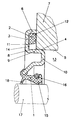
- FIG. 1 An exemplary embodiment of a radial shaft sealing ring is shown in the figure, with its centering seat 4 in the housing bore 5 of the housing 7 is pressed.
- the radial shaft seal has a dynamic load first seal 1 and a statically stressed second seal, the first seal 1 has a sealing lip 15, which is by an annular coil spring 16 is pressed in the radial direction on the shaft 17 to be sealed and this seals under radial preload.
- a face seal 18 is the side of the sealing lip 15 facing away from the space 13 arranged, which integrally merging into one another and using the same material the sealing lip 15 is formed and a component of the first seal 1 forms.
- the second seal 2 is on the side facing the housing 7 a corrugation extending in the radial direction, the Elevations and those adjacent on both sides in the radial direction Recesses are each annular in the circumferential direction.
- the support ring 3 is provided with an axial projection 6 which in the assembled state of the radial sealing ring touches the housing 7.
- the axial projection 6 protects the second seal 2 from mechanical, external Influences and an impermissibly high pressure load in the axial Direction during and after the installation of the radial shaft seal on the housing 7.
- the axial projection 6 bears against the housing 7 and prevents an even longer, unnecessarily long, the service life of the second seal 2 reducing deformation.
- the second seal 2 seals the medium to be sealed therefore has a very long service life flawlessly.
- the support ring 3 consists of a partially pullable sheet and has an essentially S-shaped Cross section on.
- the centering seat 4 is through the outer peripheral surface 8 of the Axial web 9 formed, the axial web 9, the two radial webs 10, 11 of the Support ring 3 connects together.
- the second seal 2 is on the inner circumference 12 of the axial projection 6 and with the space 13 to be sealed facing side 14 of the radially outer radial web 11 by vulcanization connected.
Landscapes
- Engineering & Computer Science (AREA)
- General Engineering & Computer Science (AREA)
- Mechanical Engineering (AREA)
- Sealing Devices (AREA)
- Sealing With Elastic Sealing Lips (AREA)
- Mechanical Sealing (AREA)
- Sealing Of Bearings (AREA)
- Earth Drilling (AREA)
- Gasket Seals (AREA)
- Diaphragms And Bellows (AREA)
Claims (5)
- Joint à lèvres radiales comprenant au moins une première lèvre (1) sollicitée dynamiquement et au moins une deuxième lèvre (2) sollicitée statiquement, qui sont reliées à un anneau d'appui (3) pouvant être fixé avec un siège de centrage (4) dans un perçage de carter (5), présentant une section transversale pour l'essentiel en forme de S ainsi qu'une saillie axiale (6), qui recouvre la deuxième lèvre (2) du moins partiellement pour limiter la déformation élastique de celle-ci et qui peut être appliquée sur un carter (7) devant être rendu étanche, caractérisé en ce que le siège de centrage (4) est formé par une surface circonférentielle extérieure (8) d'une nervure axiale (9) reliant les nervures radiales (10, 11) de l'anneau d'appui (3), et en ce que la deuxième lèvre (2) est pourvue d'une ondulation s'étendant dans le sens radial sur une face (12) orientée vers le carter (7).
- Joint à lèvres radiales selon la revendication 1, caractérisé en ce que l'ondulation s'étendant dans le sens radial comporte des élévations et des creux adjacents de part et d'autre dans le sens radial, présentant à chaque fois une forme annulaire dans le sens circonférentiel.
- Joint à lèvres radiales selon la revendication 1 ou 2, caractérisé en ce que l'anneau d'appui (3) est réalisé à partir d'un matériau semi-dur.
- Joint à lèvres radiales selon l'une des revendications 1 à 3, caractérisé en ce que la première (1) et la deuxième (2) lèvres sont réalisées à partir de matériaux élastomères différents les uns des autres, injectés séparément sur l'anneau d'appui (3).
- Joint à lèvres radiales selon l'une des revendications 1 à 4, caractérisé en ce que la deuxième lèvre (2) présente une section transversale pour l'essentiel rectangulaire et est reliée par adhésion à la périphérie intérieure (12) de la saillie axiale (6) ainsi qu'à la face (14) orientée vers l'espace (13) à rendre étanche de la nervure radiale (11) radialement extérieure.
Applications Claiming Priority (2)
| Application Number | Priority Date | Filing Date | Title |
|---|---|---|---|
| DE19711400A DE19711400C2 (de) | 1997-03-19 | 1997-03-19 | Radialwellendichtring |
| DE19711400 | 1997-03-19 |
Publications (3)
| Publication Number | Publication Date |
|---|---|
| EP0866247A2 EP0866247A2 (fr) | 1998-09-23 |
| EP0866247A3 EP0866247A3 (fr) | 1999-08-04 |
| EP0866247B1 true EP0866247B1 (fr) | 2003-04-23 |
Family
ID=7823869
Family Applications (1)
| Application Number | Title | Priority Date | Filing Date |
|---|---|---|---|
| EP97118666A Expired - Lifetime EP0866247B1 (fr) | 1997-03-19 | 1997-10-28 | Joint à lèvres radiales |
Country Status (7)
| Country | Link |
|---|---|
| US (1) | US6062571A (fr) |
| EP (1) | EP0866247B1 (fr) |
| CN (1) | CN1107827C (fr) |
| AT (1) | ATE238510T1 (fr) |
| BR (1) | BR9800923A (fr) |
| DE (2) | DE19711400C2 (fr) |
| ES (1) | ES2194143T3 (fr) |
Families Citing this family (6)
| Publication number | Priority date | Publication date | Assignee | Title |
|---|---|---|---|---|
| US6634648B1 (en) * | 2000-06-29 | 2003-10-21 | Kelsey-Hayes Company | Shield and seal assembly for vehicle wheel end assembly |
| DE10235079A1 (de) * | 2002-07-31 | 2004-02-19 | Carl Freudenberg Kg | Manschettendichtung |
| EP2211076B1 (fr) * | 2009-01-21 | 2015-09-02 | Carl Freudenberg KG | Joint d'étanchéité |
| JP5311649B2 (ja) * | 2009-03-30 | 2013-10-09 | 内山工業株式会社 | 環状密封装置 |
| DE102010001345B4 (de) * | 2010-01-28 | 2013-09-19 | Trelleborg Sealing Solutions Germany Gmbh | Drehdurchführung |
| US11084551B1 (en) | 2020-04-22 | 2021-08-10 | Peter Stull | Foldable recumbent tricycle frame |
Citations (1)
| Publication number | Priority date | Publication date | Assignee | Title |
|---|---|---|---|---|
| DE3038717A1 (de) * | 1979-09-25 | 1982-05-27 | Polimac S.a.s. di Pelissero-Panchetti & C., 10151 Torino | Radialdichtung |
Family Cites Families (15)
| Publication number | Priority date | Publication date | Assignee | Title |
|---|---|---|---|---|
| US2105871A (en) * | 1936-03-20 | 1938-01-18 | Nat Bearing Metals Corp | Oil and dust seal for journal boxes |
| US3843139A (en) * | 1970-12-23 | 1974-10-22 | Garlock Inc | Oil seal |
| US4156531A (en) * | 1976-10-04 | 1979-05-29 | Esco Transmissions | Sealing ring for flexible toothed coupling and couplings provided with such rings |
| DE2653457C3 (de) * | 1976-11-25 | 1980-09-11 | Goetze Ag, 5093 Burscheid | Lippendichtungsring |
| FR2452633A1 (fr) * | 1979-03-29 | 1980-10-24 | Skf Cie Applic Mecanique | Butee d'embrayage a auto-alignement elastique comportant une douille de guidage composite |
| JPH067220Y2 (ja) * | 1986-08-13 | 1994-02-23 | 株式会社共立 | オイルシール |
| DE3634735A1 (de) * | 1986-10-11 | 1988-04-21 | Goetze Ag | Verschlussdeckel, insbesondere fuer kurbelwellen- und getriebegehaeuse bei kraftfahrzeugen |
| US5018750A (en) * | 1989-06-02 | 1991-05-28 | Deere & Company | Shaft seal assembly |
| DE4123688A1 (de) * | 1991-07-17 | 1993-01-21 | Goetze Ag | Wellendichtring |
| FR2682441B1 (fr) * | 1991-10-15 | 1993-12-10 | Procal | Tube-guide a etancheite integree pour butee de debrayage de boite de vitesses de vehicule automobile. |
| US5167419A (en) * | 1991-10-22 | 1992-12-01 | Freudenberg-Nok General Partnership | Fluid seal with integral check valve |
| DE4224179C1 (de) | 1992-07-22 | 1993-11-11 | Freudenberg Carl Fa | Führungshülse mit integrierter Dichtung für ein Kupplungsausrücklager eines Getriebes |
| DE9303000U1 (de) * | 1993-03-02 | 1993-04-22 | Goetze Ag, 5093 Burscheid | Kupplungsausrücklagerführung |
| DE29603159U1 (de) * | 1996-02-22 | 1996-05-02 | CR Elastomere GmbH, 51379 Leverkusen | Verschlußdeckel, insbesondere für Motor- und Getriebegehäuse bei Kraftfahrzeugen |
| FR2745618B1 (fr) * | 1996-02-29 | 1999-01-08 | Valeo | Dispositif de debrayage pour embrayage de vehicule automobile comportant un joint d'arbre tournant perfectionne |
-
1997
- 1997-03-19 DE DE19711400A patent/DE19711400C2/de not_active Expired - Lifetime
- 1997-10-28 DE DE59709910T patent/DE59709910D1/de not_active Expired - Lifetime
- 1997-10-28 AT AT97118666T patent/ATE238510T1/de not_active IP Right Cessation
- 1997-10-28 EP EP97118666A patent/EP0866247B1/fr not_active Expired - Lifetime
- 1997-10-28 ES ES97118666T patent/ES2194143T3/es not_active Expired - Lifetime
-
1998
- 1998-01-09 US US09/004,840 patent/US6062571A/en not_active Expired - Fee Related
- 1998-03-17 CN CN98105709A patent/CN1107827C/zh not_active Expired - Fee Related
- 1998-03-17 BR BR9800923-0A patent/BR9800923A/pt not_active IP Right Cessation
Patent Citations (1)
| Publication number | Priority date | Publication date | Assignee | Title |
|---|---|---|---|---|
| DE3038717A1 (de) * | 1979-09-25 | 1982-05-27 | Polimac S.a.s. di Pelissero-Panchetti & C., 10151 Torino | Radialdichtung |
Also Published As
| Publication number | Publication date |
|---|---|
| ES2194143T3 (es) | 2003-11-16 |
| US6062571A (en) | 2000-05-16 |
| CN1193702A (zh) | 1998-09-23 |
| BR9800923A (pt) | 1999-09-21 |
| EP0866247A3 (fr) | 1999-08-04 |
| ATE238510T1 (de) | 2003-05-15 |
| DE19711400A1 (de) | 1998-10-01 |
| CN1107827C (zh) | 2003-05-07 |
| DE59709910D1 (de) | 2003-05-28 |
| DE19711400C2 (de) | 2001-12-06 |
| EP0866247A2 (fr) | 1998-09-23 |
Similar Documents
| Publication | Publication Date | Title |
|---|---|---|
| EP0774568B1 (fr) | Dispositif d'étanchéité pour une queue de soupape | |
| EP0922888A2 (fr) | Anneau d'étanchéité | |
| EP1995088B1 (fr) | Elément de palier d'insertion, élément de palier d'insertion élastique et dispositif de support de jambe de suspension à ressort | |
| EP0382197A1 (fr) | Disque d'embrayage | |
| EP0810399A2 (fr) | Raccord emboîtable pour systèmes à fluide sous pression | |
| DE102020208236B4 (de) | Dichtungsanordnung und Verfahren zur Herstellung einer Dichtungsanordnung | |
| EP0472828B1 (fr) | Palier pour levier de changement de vitesse | |
| EP2827026B1 (fr) | Dispositif d'étanchéité dotée d'une bague d'étanchéité | |
| EP1026428A2 (fr) | Bague d'étanchéité | |
| EP0866247B1 (fr) | Joint à lèvres radiales | |
| WO2015022144A1 (fr) | Bague d'étanchéité | |
| EP0829663B1 (fr) | Garniture mécanique d'étanchéité | |
| DE19754400C2 (de) | Kassettendichtung | |
| EP3771841B1 (fr) | Coussinet de palier pour une articulation à rotule ainsi qu'articulation à rotule | |
| EP0565771B1 (fr) | Joint de moyeu | |
| WO2001031211A1 (fr) | Bague a tolerance d'un palier radial | |
| DE3838996C2 (fr) | ||
| EP1055849B1 (fr) | Joint d'étanchéité pour chambres sous pression | |
| EP2466172A1 (fr) | Bague d'étanchéité | |
| EP2251572B1 (fr) | Agencement d'étanchéification | |
| DE8214684U1 (de) | Daempfungsscheibe | |
| DE19916625C1 (de) | Kolben mit integriertem Federelement | |
| EP1475285B1 (fr) | Support d'un arbre à bord d'un véhicule | |
| EP0259714A1 (fr) | Buteé | |
| DE102022113155B4 (de) | Elastomerlager mit Schutzkappe |
Legal Events
| Date | Code | Title | Description |
|---|---|---|---|
| PUAI | Public reference made under article 153(3) epc to a published international application that has entered the european phase |
Free format text: ORIGINAL CODE: 0009012 |
|
| AK | Designated contracting states |
Kind code of ref document: A2 Designated state(s): AT DE ES FR GB IT SE |
|
| AX | Request for extension of the european patent |
Free format text: AL;LT;LV;RO;SI |
|
| PUAL | Search report despatched |
Free format text: ORIGINAL CODE: 0009013 |
|
| AK | Designated contracting states |
Kind code of ref document: A3 Designated state(s): AT BE CH DE DK ES FI FR GB GR IE IT LI LU MC NL PT SE |
|
| AX | Request for extension of the european patent |
Free format text: AL;LT;LV;RO;SI |
|
| 17P | Request for examination filed |
Effective date: 19990710 |
|
| AKX | Designation fees paid |
Free format text: AT DE ES FR GB IT SE |
|
| 17Q | First examination report despatched |
Effective date: 20010525 |
|
| RAP1 | Party data changed (applicant data changed or rights of an application transferred) |
Owner name: CARL FREUDENBERG KG |
|
| GRAH | Despatch of communication of intention to grant a patent |
Free format text: ORIGINAL CODE: EPIDOS IGRA |
|
| GRAH | Despatch of communication of intention to grant a patent |
Free format text: ORIGINAL CODE: EPIDOS IGRA |
|
| GRAA | (expected) grant |
Free format text: ORIGINAL CODE: 0009210 |
|
| AK | Designated contracting states |
Designated state(s): AT DE ES FR GB IT SE |
|
| REG | Reference to a national code |
Ref country code: GB Ref legal event code: FG4D Free format text: NOT ENGLISH |
|
| REF | Corresponds to: |
Ref document number: 59709910 Country of ref document: DE Date of ref document: 20030528 Kind code of ref document: P |
|
| GBT | Gb: translation of ep patent filed (gb section 77(6)(a)/1977) | ||
| REG | Reference to a national code |
Ref country code: SE Ref legal event code: TRGR |
|
| ET | Fr: translation filed | ||
| REG | Reference to a national code |
Ref country code: ES Ref legal event code: FG2A Ref document number: 2194143 Country of ref document: ES Kind code of ref document: T3 |
|
| PLBE | No opposition filed within time limit |
Free format text: ORIGINAL CODE: 0009261 |
|
| STAA | Information on the status of an ep patent application or granted ep patent |
Free format text: STATUS: NO OPPOSITION FILED WITHIN TIME LIMIT |
|
| 26N | No opposition filed |
Effective date: 20040126 |
|
| PGFP | Annual fee paid to national office [announced via postgrant information from national office to epo] |
Ref country code: GB Payment date: 20040913 Year of fee payment: 8 |
|
| PGFP | Annual fee paid to national office [announced via postgrant information from national office to epo] |
Ref country code: ES Payment date: 20041008 Year of fee payment: 8 |
|
| PGFP | Annual fee paid to national office [announced via postgrant information from national office to epo] |
Ref country code: FR Payment date: 20041020 Year of fee payment: 8 Ref country code: AT Payment date: 20041020 Year of fee payment: 8 |
|
| PGFP | Annual fee paid to national office [announced via postgrant information from national office to epo] |
Ref country code: SE Payment date: 20041026 Year of fee payment: 8 |
|
| PG25 | Lapsed in a contracting state [announced via postgrant information from national office to epo] |
Ref country code: IT Free format text: LAPSE BECAUSE OF NON-PAYMENT OF DUE FEES;WARNING: LAPSES OF ITALIAN PATENTS WITH EFFECTIVE DATE BEFORE 2007 MAY HAVE OCCURRED AT ANY TIME BEFORE 2007. THE CORRECT EFFECTIVE DATE MAY BE DIFFERENT FROM THE ONE RECORDED. Effective date: 20051028 Ref country code: GB Free format text: LAPSE BECAUSE OF NON-PAYMENT OF DUE FEES Effective date: 20051028 Ref country code: AT Free format text: LAPSE BECAUSE OF NON-PAYMENT OF DUE FEES Effective date: 20051028 |
|
| PG25 | Lapsed in a contracting state [announced via postgrant information from national office to epo] |
Ref country code: SE Free format text: LAPSE BECAUSE OF NON-PAYMENT OF DUE FEES Effective date: 20051029 Ref country code: ES Free format text: LAPSE BECAUSE OF NON-PAYMENT OF DUE FEES Effective date: 20051029 |
|
| EUG | Se: european patent has lapsed | ||
| GBPC | Gb: european patent ceased through non-payment of renewal fee |
Effective date: 20051028 |
|
| PG25 | Lapsed in a contracting state [announced via postgrant information from national office to epo] |
Ref country code: FR Free format text: LAPSE BECAUSE OF NON-PAYMENT OF DUE FEES Effective date: 20060630 |
|
| REG | Reference to a national code |
Ref country code: FR Ref legal event code: ST Effective date: 20060630 |
|
| REG | Reference to a national code |
Ref country code: ES Ref legal event code: FD2A Effective date: 20051029 |
|
| PGFP | Annual fee paid to national office [announced via postgrant information from national office to epo] |
Ref country code: DE Payment date: 20161101 Year of fee payment: 20 |
|
| REG | Reference to a national code |
Ref country code: DE Ref legal event code: R071 Ref document number: 59709910 Country of ref document: DE |