EP1475285B1 - Support d'un arbre à bord d'un véhicule - Google Patents
Support d'un arbre à bord d'un véhicule Download PDFInfo
- Publication number
- EP1475285B1 EP1475285B1 EP04009177A EP04009177A EP1475285B1 EP 1475285 B1 EP1475285 B1 EP 1475285B1 EP 04009177 A EP04009177 A EP 04009177A EP 04009177 A EP04009177 A EP 04009177A EP 1475285 B1 EP1475285 B1 EP 1475285B1
- Authority
- EP
- European Patent Office
- Prior art keywords
- bearing
- shaft
- wiper shaft
- bearing body
- ring
- Prior art date
- Legal status (The legal status is an assumption and is not a legal conclusion. Google has not performed a legal analysis and makes no representation as to the accuracy of the status listed.)
- Expired - Lifetime
Links
- 208000027418 Wounds and injury Diseases 0.000 description 9
- 230000006378 damage Effects 0.000 description 9
- 208000014674 injury Diseases 0.000 description 9
- 238000006073 displacement reaction Methods 0.000 description 3
- 241000309551 Arthraxon hispidus Species 0.000 description 2
- 238000010521 absorption reaction Methods 0.000 description 2
- 238000010586 diagram Methods 0.000 description 2
- 230000035939 shock Effects 0.000 description 2
- XLYOFNOQVPJJNP-UHFFFAOYSA-N water Substances O XLYOFNOQVPJJNP-UHFFFAOYSA-N 0.000 description 2
- 230000001133 acceleration Effects 0.000 description 1
- 230000015572 biosynthetic process Effects 0.000 description 1
- 238000011109 contamination Methods 0.000 description 1
- 230000003116 impacting effect Effects 0.000 description 1
- 230000037431 insertion Effects 0.000 description 1
- 238000003780 insertion Methods 0.000 description 1
- 230000000750 progressive effect Effects 0.000 description 1
- 238000007789 sealing Methods 0.000 description 1
- 239000007787 solid Substances 0.000 description 1
Images


Classifications
-
- B—PERFORMING OPERATIONS; TRANSPORTING
- B60—VEHICLES IN GENERAL
- B60S—SERVICING, CLEANING, REPAIRING, SUPPORTING, LIFTING, OR MANOEUVRING OF VEHICLES, NOT OTHERWISE PROVIDED FOR
- B60S1/00—Cleaning of vehicles
- B60S1/02—Cleaning windscreens, windows or optical devices
- B60S1/04—Wipers or the like, e.g. scrapers
- B60S1/0488—Wiper arrangement for crash protection or impact absorption
-
- B—PERFORMING OPERATIONS; TRANSPORTING
- B60—VEHICLES IN GENERAL
- B60S—SERVICING, CLEANING, REPAIRING, SUPPORTING, LIFTING, OR MANOEUVRING OF VEHICLES, NOT OTHERWISE PROVIDED FOR
- B60S1/00—Cleaning of vehicles
- B60S1/02—Cleaning windscreens, windows or optical devices
- B60S1/04—Wipers or the like, e.g. scrapers
- B60S1/32—Wipers or the like, e.g. scrapers characterised by constructional features of wiper blade arms or blades
- B60S1/34—Wiper arms; Mountings therefor
-
- B—PERFORMING OPERATIONS; TRANSPORTING
- B60—VEHICLES IN GENERAL
- B60S—SERVICING, CLEANING, REPAIRING, SUPPORTING, LIFTING, OR MANOEUVRING OF VEHICLES, NOT OTHERWISE PROVIDED FOR
- B60S1/00—Cleaning of vehicles
- B60S1/02—Cleaning windscreens, windows or optical devices
- B60S1/04—Wipers or the like, e.g. scrapers
- B60S1/32—Wipers or the like, e.g. scrapers characterised by constructional features of wiper blade arms or blades
- B60S1/34—Wiper arms; Mountings therefor
- B60S1/3488—Means for mounting wiper arms onto the vehicle
- B60S1/3493—Means for mounting the wiper shaft in the wiper bearing
Definitions
- the invention relates to an impact-soft mounting of a windshield wiper shaft on a vehicle, which is substantially unloaded under normal operating conditions in its axial direction and in the event of an impact represents a significant risk of injury to a collision involved.
- a vehicle body facility In the context of increasing safety requirements for vehicles, the protection of accident participants, such as pedestrians, cyclists or inline skaters, increased attention in an impact, and measures are taken that reduce the risk of injury to an accident.
- Some necessary on a vehicle body facilities are arranged on this so that they represent an increased risk of injury to the accident involved in an impact, in particular antennas or windscreen wiper systems.
- the latter usually have an outwardly projecting windshield wiper shaft for the respective windscreen wiper in the region of the water box on the vehicle body.
- a windshield wiper shaft is mounted on a bearing body fixedly connected to the vehicle body with a snap ring, which engages in a circumferential groove formed on the shaft and fixes the windshield wiper shaft in the axial shaft direction.
- the bearing has a bearing on a vehicle-fixed bearing body with a cylindrical receptacle for the windshield wiper shaft, a supported on the vehicle interior end face snap ring, which is interrupted over its circumference at one point and with which the windshield wiper shaft in the axial direction is engaged, and one for Attachment to the snap ring on the Legerenia opposite side formed on the windshield wiper shaft shaft shoulder.
- the snap ring is provided with a tapering or widening in the axial direction conical surface and corresponds with this with a formed on the windshield wiper shaft or the bearing body conical surface.
- the snap ring In a sudden axial impact load, the snap ring is widened or compressed depending on the configuration of the arrangement due to the respective cooperating conical surface pair, and the windshield wiper shaft is pressed in the axial direction by the snap ring or together with this through the recording. If a windshield wiper shaft is mounted on a windshield wiper in such a way, the risk of injury for a collision impacting on the windshield wiper is reduced. The displacement of the respective windshield wiper shaft and arranged on this windscreen wiper is determined by the recording and the spatial conditions under the vehicle body. But the storage is reasonably expensive because of the formation of the corresponding surfaces.
- the invention consists in an impact-soft mounting of a windshield wiper shaft on a vehicle having a vehicle-fixed bearing body with a cylindrical receptacle for the windshield wiper shaft, a supported on the vehicle interior end face snap ring and a trained on the snap ring on the bearing body side facing away from the windshield wiper shaft Has shaft shoulder.
- the snap ring sits on the shaft shoulder in a provided on the windshield wiper shaft circumferential groove, which provided perpendicular to the shaft axis groove wall forms the contact surface for the snap ring in the form of a concentric contact shoulder with small radial extent and circumferentially to the shaft region with the larger diameter toward a chamfer is arranged which is connected directly to the contact shoulder.
- the impact-soft arrangement is such that the bearing body is provided with a bearing bush, which forms an axial gap in the region of the free end of the bearing body with this and the shaft, in which an O-ring is used for radial sealing.
- This gap is closed by a disk arranged on the end face of the bearing body, the inner diameter of which corresponds to the outer diameter of the shaft, whereby a seal in the axial direction is also provided.
- the snap ring is arranged and engages in the formed in the shaft circumferential groove, wherein the inner diameter is smaller than that of the disc and corresponds to the core diameter of the shaft in the region of the groove.
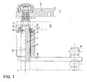
- Fig. 1 is an impact-soft storage of a windshield wiper shaft 1 shown with a wiper arm 2 attached thereto a windshield wiper system on a motor vehicle.
- the Wiper shaft 1 is received in a provided with a (sliding) bearing bush 3 bearing body 4 and secured by a radially slotted snap ring 5 against movement in the axial direction, wherein the snap ring 5 is supported on a arranged on the end face of the bearing body 4 disc 6.
- the arrangement is surrounded by a cap 7, which is shown cut, and thus protected from contamination and water.
- the arrangement is in Fig. 2 shown enlarged and will be explained below.
- the wiper shaft 1 is fixedly connected to a rocker arm 8 with a ball joint head 9 and is driven by this oscillating.
- Fig. 1 shows the windshield wiper shaft 1 with the wiper arm 2 in the normal operating position I in solid and in an impact position II in dash-dotted lines.
- the bearing body 4 is how Fig. 2 shows clarified, provided with a bearing bush 3, on which in an intermediate between these (3, 4) and the wiper shaft 1 formed gap 10, an O-ring 11 is arranged.
- This gap 10 is closed by the disc 6, such that the O-ring 11 seals the windshield wiper shaft 1 relative to the bearing body 4 in the radial direction, wherein the disc 6 rests directly and whose inner diameter corresponds to the nominal diameter of the windshield wiper shaft 1. Therefore, the gap 10 is also sealed in the axial direction.
- Fig. 2 further shows that the windshield wiper shaft 1 is provided with a circumferential groove 12, in which engages the snap ring 5 disposed on the disc 6 and the plate 6 is slightly pressurized.
- Their (12) bearing body-side boundary surface 13 is bevelled with respect to the axis A of the windshield wiper shaft 1, wherein the groove edge formed by this rests against the inner surface of the disc 6.
- circumferential groove 12 of the snap ring 5 engages in such a way that the windshield wiper shaft 1 with the abutment shoulder 15 bears against this and is thereby fixed in the axial direction on the bearing body 4.
- the wiper arm 2 is impacted with an impact force (arrow, Fig. 1 )
- the narrow abutment shoulder 15 is pressed onto the snap ring 5, which is thereby deformed and expanded with energy absorption, and the windshield wiper shaft 1 enters with the chamfer 16 in the snap ring 5, which is thereby amplified under energy absorption, maximally up to a natural " Stop on the vehicle
- the impressions of the windshield wiper shaft 1 may be completed but before, namely, when the impact energy is consumed.
- the results in Fig. 3 illustrated force-displacement diagram.
- the circumferential groove does not form a contact shoulder with a chamfer connected and in which a force of substantially 4000 N is required to press the windshield wiper shaft 1
- only a force of substantially 1100 N is required.
Landscapes
- Engineering & Computer Science (AREA)
- Mechanical Engineering (AREA)
- Mounting Of Bearings Or Others (AREA)
- Automobile Manufacture Line, Endless Track Vehicle, Trailer (AREA)
- Replacement Of Web Rolls (AREA)
- Support Of The Bearing (AREA)
Claims (4)
- Support de palier souple en cas de collision pour un arbre d'essuie-glace sur un véhicule, dans lequel l'arbre d'essuie-glace (1) est déplacé par une contrainte de choc exercée en cas de collision sur celui-ci, dans la direction essentiellement axiale vers l'intérieur du véhicule, avec un corps de palier (4) fixé au véhicule, avec un logement cylindrique pour l'arbre d'essuie-glace (1), un jonc élastique (5) supporté sur son côté frontal opposé à l'intérieur du véhicule, et un gradin d'arbre (14) réalisé pour s'appliquer contre le jonc élastique (5) sur le côté opposé au corps de palier (4) sur l'arbre d'essuie-glace (1), caractérisé en ce que le jonc élastique (5) sur le gradin d'arbre (14) repose dans une rainure périphérique (12) prévue sur l'arbre d'essuie-glace (1) et la paroi de la rainure prévue perpendiculairement à l'axe de l'arbre (A) forme la surface d'appui du jonc élastique (5) en forme d'épaulement d'appui concentrique (15) de faible étendue radiale, et du côté périphérique vers la région de l'arbre ayant le plus grand diamètre est disposé un biseau (16) qui est directement raccordé à l'épaulement d'appui (15).
- Support de palier selon la revendication 1, caractérisé en ce que l'épaulement d'appui (15) a une largeur (b) substantiellement de l'ordre de 0,1 à 0,3 mm.
- Support de palier selon la revendication 1, caractérisé en ce que le biseau (16) forme avec l'axe (A) de l'arbre d'essuie-glace (1) un angle (β) substantiellement compris entre 45 et 15 degrés, en particulier toutefois un angle (β) de 30 degrés.
- Support de palier selon la revendication 1, caractérisé en ce que le corps de palier (4) est pourvu d'une douille de palier (3) qui constitue du côté du jonc élastique avec le corps de palier (4) et l'arbre d'essuie-glace (1) une fente (10) pour recevoir un joint torique (11), qui réalise l'étanchéité de l'arbre d'essuie-glace (1) par rapport au corps de palier (4) dans la direction radiale, en ce que la fente (10) est fermée du côté du jonc élastique par une rondelle (6) située sur la surface frontale du corps de palier (4) et sur le joint torique (11) et est étanchée dans la direction radiale, et en ce que l'agencement est entouré par un capuchon de recouvrement (7).
Applications Claiming Priority (2)
| Application Number | Priority Date | Filing Date | Title |
|---|---|---|---|
| DE10320933 | 2003-05-09 | ||
| DE10320933A DE10320933A1 (de) | 2003-05-09 | 2003-05-09 | Aufprallweiche Lagerung einer Welle an einem Fahrzeug |
Publications (2)
| Publication Number | Publication Date |
|---|---|
| EP1475285A1 EP1475285A1 (fr) | 2004-11-10 |
| EP1475285B1 true EP1475285B1 (fr) | 2009-04-01 |
Family
ID=32981311
Family Applications (1)
| Application Number | Title | Priority Date | Filing Date |
|---|---|---|---|
| EP04009177A Expired - Lifetime EP1475285B1 (fr) | 2003-05-09 | 2004-04-17 | Support d'un arbre à bord d'un véhicule |
Country Status (3)
| Country | Link |
|---|---|
| EP (1) | EP1475285B1 (fr) |
| AT (1) | ATE427250T1 (fr) |
| DE (2) | DE10320933A1 (fr) |
Families Citing this family (3)
| Publication number | Priority date | Publication date | Assignee | Title |
|---|---|---|---|---|
| DE10352468A1 (de) | 2003-11-07 | 2005-06-02 | Robert Bosch Gmbh | Scheibenwischvorrichtung, insbesondere für ein Kraftfahrzeug |
| DE102005035088A1 (de) * | 2005-07-27 | 2007-02-01 | Robert Bosch Gmbh | Scheibenwischvorrichtung, insbesondere für ein Kraftfahrzeug |
| DE102015221741A1 (de) * | 2015-11-05 | 2017-05-11 | Robert Bosch Gmbh | Scheibenwischvorrichtung, insbesondere für ein Kraftfahrzeug |
Family Cites Families (8)
| Publication number | Priority date | Publication date | Assignee | Title |
|---|---|---|---|---|
| DE59708231D1 (de) * | 1996-05-10 | 2002-10-24 | Volkswagen Ag | Vorrichtung zur axialen Fixierung einer axial im wesentlichen unbelasteten Welle |
| JPH11139256A (ja) * | 1997-11-11 | 1999-05-25 | Jidosha Denki Kogyo Co Ltd | 自動車用ワイパー |
| JP3423870B2 (ja) * | 1997-11-11 | 2003-07-07 | 自動車電機工業株式会社 | 自動車用ワイパー |
| JP4024316B2 (ja) * | 1998-01-29 | 2007-12-19 | ローベルト ボツシユ ゲゼルシヤフト ミツト ベシユレンクテル ハフツング | ワイパ装置 |
| US6317918B1 (en) * | 1998-04-24 | 2001-11-20 | Honda Giken Kogyo Kabushiki Kaisha | Windshield wiper device for vehicle |
| JPH11334539A (ja) * | 1998-05-22 | 1999-12-07 | Honda Motor Co Ltd | 車両用ワイパ装置 |
| JP3564007B2 (ja) * | 1999-08-05 | 2004-09-08 | 株式会社ミツバ | 車両用ワイパ装置 |
| US20020165033A1 (en) * | 2001-05-04 | 2002-11-07 | Sunonwealth Electric Machine Industry Co., Ltd. | Rotor shafts |
-
2003
- 2003-05-09 DE DE10320933A patent/DE10320933A1/de not_active Withdrawn
-
2004
- 2004-04-17 AT AT04009177T patent/ATE427250T1/de not_active IP Right Cessation
- 2004-04-17 EP EP04009177A patent/EP1475285B1/fr not_active Expired - Lifetime
- 2004-04-17 DE DE502004009255T patent/DE502004009255D1/de not_active Expired - Lifetime
Also Published As
| Publication number | Publication date |
|---|---|
| DE10320933A1 (de) | 2004-12-02 |
| DE502004009255D1 (de) | 2009-05-14 |
| ATE427250T1 (de) | 2009-04-15 |
| EP1475285A1 (fr) | 2004-11-10 |
Similar Documents
| Publication | Publication Date | Title |
|---|---|---|
| EP0806329B1 (fr) | Dispositif de support d'un arbre non chargé axialement | |
| DE60026667T2 (de) | Wischanlage für Kraftfahrzeuge | |
| EP1263632B1 (fr) | Dispositif d'essuyage | |
| EP2414180B1 (fr) | Articulation elastomere | |
| DE3518634C2 (fr) | ||
| EP1458596B1 (fr) | Fixation d'un systeme d'essuie-glace | |
| DE10161715A1 (de) | Elektrische Hilfskraftlenkung für Kraftfahrzeuge | |
| DE3525213A1 (de) | Elastische buchse | |
| DE102009029569A1 (de) | Vorrichtung zur schwingungsdämpfenden Lagerung eines Fluidaggregats und zugehöriges Fluidaggregat | |
| EP1031756B1 (fr) | Fixation d'un soufflet roulant d'un ressort pneumatique sur un élément de support | |
| EP0229940B1 (fr) | Support élastique pour le montage d'une cabine de chauffeur de camion | |
| DE10343572A1 (de) | Aufprallweiche Lagerung einer Antriebswelle eines Scheibenwischers an einem Fahrzeug | |
| EP0656271A1 (fr) | Pivot, en particulier pour un guide d'essieu d'un véhicule à moteur | |
| EP1475285A1 (fr) | Support d'un arbre à bord d'un véhicule | |
| DE2818246A1 (de) | Sicherheitsgurtsystem fuer kraftfahrzeuge mit plastisch deformierbaren einrichtungen | |
| DE19946923B4 (de) | Nabenabdeckung für eine Radlagerung, vorzugsweise für eine Nutzfahrzeug-Radlagerung | |
| EP0779186A2 (fr) | Volant avec système de retenue pour occupant | |
| DE10343573A1 (de) | Aufprallweiche Lagerung einer Antriebswelle eines Scheibenwischers an einem Fahrzeug | |
| DE102010017227A1 (de) | Luftfeder für Fahrzeuge | |
| EP1820994B1 (fr) | Pendule, en particulier pour le train d'atterrissage d'un véhicule utilitaire | |
| DE102009015025A1 (de) | Wälzlageranordnung | |
| EP2060415B1 (fr) | Attelage à ressort prémonté | |
| EP2032400B1 (fr) | Commande d'essuie-glace par moteur electrique | |
| EP1493939B1 (fr) | Fixation d'un tube de protection à un dispositif de réglage | |
| DE102017223298A1 (de) | Lenksäule für ein Kraftfahrzeug |
Legal Events
| Date | Code | Title | Description |
|---|---|---|---|
| PUAI | Public reference made under article 153(3) epc to a published international application that has entered the european phase |
Free format text: ORIGINAL CODE: 0009012 |
|
| AK | Designated contracting states |
Kind code of ref document: A1 Designated state(s): AT BE BG CH CY CZ DE DK EE ES FI FR GB GR HU IE IT LI LU MC NL PL PT RO SE SI SK TR |
|
| AX | Request for extension of the european patent |
Extension state: AL HR LT LV MK |
|
| 17P | Request for examination filed |
Effective date: 20050510 |
|
| AKX | Designation fees paid |
Designated state(s): AT BE BG CH CY CZ DE DK EE ES FI FR GB GR HU IE IT LI LU MC NL PL PT RO SE SI SK TR |
|
| GRAP | Despatch of communication of intention to grant a patent |
Free format text: ORIGINAL CODE: EPIDOSNIGR1 |
|
| GRAS | Grant fee paid |
Free format text: ORIGINAL CODE: EPIDOSNIGR3 |
|
| GRAA | (expected) grant |
Free format text: ORIGINAL CODE: 0009210 |
|
| AK | Designated contracting states |
Kind code of ref document: B1 Designated state(s): AT BE BG CH CY CZ DE DK EE ES FI FR GB GR HU IE IT LI LU MC NL PL PT RO SE SI SK TR |
|
| REG | Reference to a national code |
Ref country code: GB Ref legal event code: FG4D Free format text: NOT ENGLISH |
|
| REG | Reference to a national code |
Ref country code: CH Ref legal event code: EP |
|
| REG | Reference to a national code |
Ref country code: IE Ref legal event code: FG4D Free format text: LANGUAGE OF EP DOCUMENT: GERMAN |
|
| REF | Corresponds to: |
Ref document number: 502004009255 Country of ref document: DE Date of ref document: 20090514 Kind code of ref document: P |
|
| PG25 | Lapsed in a contracting state [announced via postgrant information from national office to epo] |
Ref country code: SI Free format text: LAPSE BECAUSE OF FAILURE TO SUBMIT A TRANSLATION OF THE DESCRIPTION OR TO PAY THE FEE WITHIN THE PRESCRIBED TIME-LIMIT Effective date: 20090401 |
|
| NLV1 | Nl: lapsed or annulled due to failure to fulfill the requirements of art. 29p and 29m of the patents act | ||
| REG | Reference to a national code |
Ref country code: IE Ref legal event code: FD4D |
|
| PG25 | Lapsed in a contracting state [announced via postgrant information from national office to epo] |
Ref country code: PT Free format text: LAPSE BECAUSE OF FAILURE TO SUBMIT A TRANSLATION OF THE DESCRIPTION OR TO PAY THE FEE WITHIN THE PRESCRIBED TIME-LIMIT Effective date: 20090902 Ref country code: EE Free format text: LAPSE BECAUSE OF FAILURE TO SUBMIT A TRANSLATION OF THE DESCRIPTION OR TO PAY THE FEE WITHIN THE PRESCRIBED TIME-LIMIT Effective date: 20090401 Ref country code: FI Free format text: LAPSE BECAUSE OF FAILURE TO SUBMIT A TRANSLATION OF THE DESCRIPTION OR TO PAY THE FEE WITHIN THE PRESCRIBED TIME-LIMIT Effective date: 20090401 Ref country code: ES Free format text: LAPSE BECAUSE OF FAILURE TO SUBMIT A TRANSLATION OF THE DESCRIPTION OR TO PAY THE FEE WITHIN THE PRESCRIBED TIME-LIMIT Effective date: 20090712 |
|
| BERE | Be: lapsed |
Owner name: VOLKSWAGEN A.G. Effective date: 20090430 |
|
| PG25 | Lapsed in a contracting state [announced via postgrant information from national office to epo] |
Ref country code: SE Free format text: LAPSE BECAUSE OF FAILURE TO SUBMIT A TRANSLATION OF THE DESCRIPTION OR TO PAY THE FEE WITHIN THE PRESCRIBED TIME-LIMIT Effective date: 20090701 Ref country code: PL Free format text: LAPSE BECAUSE OF FAILURE TO SUBMIT A TRANSLATION OF THE DESCRIPTION OR TO PAY THE FEE WITHIN THE PRESCRIBED TIME-LIMIT Effective date: 20090401 Ref country code: NL Free format text: LAPSE BECAUSE OF FAILURE TO SUBMIT A TRANSLATION OF THE DESCRIPTION OR TO PAY THE FEE WITHIN THE PRESCRIBED TIME-LIMIT Effective date: 20090401 |
|
| REG | Reference to a national code |
Ref country code: CH Ref legal event code: PL |
|
| PG25 | Lapsed in a contracting state [announced via postgrant information from national office to epo] |
Ref country code: RO Free format text: LAPSE BECAUSE OF FAILURE TO SUBMIT A TRANSLATION OF THE DESCRIPTION OR TO PAY THE FEE WITHIN THE PRESCRIBED TIME-LIMIT Effective date: 20090401 Ref country code: LI Free format text: LAPSE BECAUSE OF NON-PAYMENT OF DUE FEES Effective date: 20090430 Ref country code: DK Free format text: LAPSE BECAUSE OF FAILURE TO SUBMIT A TRANSLATION OF THE DESCRIPTION OR TO PAY THE FEE WITHIN THE PRESCRIBED TIME-LIMIT Effective date: 20090401 Ref country code: CZ Free format text: LAPSE BECAUSE OF FAILURE TO SUBMIT A TRANSLATION OF THE DESCRIPTION OR TO PAY THE FEE WITHIN THE PRESCRIBED TIME-LIMIT Effective date: 20090401 Ref country code: CH Free format text: LAPSE BECAUSE OF NON-PAYMENT OF DUE FEES Effective date: 20090430 Ref country code: IE Free format text: LAPSE BECAUSE OF FAILURE TO SUBMIT A TRANSLATION OF THE DESCRIPTION OR TO PAY THE FEE WITHIN THE PRESCRIBED TIME-LIMIT Effective date: 20090401 |
|
| PLBE | No opposition filed within time limit |
Free format text: ORIGINAL CODE: 0009261 |
|
| STAA | Information on the status of an ep patent application or granted ep patent |
Free format text: STATUS: NO OPPOSITION FILED WITHIN TIME LIMIT |
|
| PG25 | Lapsed in a contracting state [announced via postgrant information from national office to epo] |
Ref country code: SK Free format text: LAPSE BECAUSE OF FAILURE TO SUBMIT A TRANSLATION OF THE DESCRIPTION OR TO PAY THE FEE WITHIN THE PRESCRIBED TIME-LIMIT Effective date: 20090401 |
|
| 26N | No opposition filed |
Effective date: 20100105 |
|
| PG25 | Lapsed in a contracting state [announced via postgrant information from national office to epo] |
Ref country code: BG Free format text: LAPSE BECAUSE OF FAILURE TO SUBMIT A TRANSLATION OF THE DESCRIPTION OR TO PAY THE FEE WITHIN THE PRESCRIBED TIME-LIMIT Effective date: 20090701 |
|
| PG25 | Lapsed in a contracting state [announced via postgrant information from national office to epo] |
Ref country code: MC Free format text: LAPSE BECAUSE OF NON-PAYMENT OF DUE FEES Effective date: 20090430 |
|
| PG25 | Lapsed in a contracting state [announced via postgrant information from national office to epo] |
Ref country code: BE Free format text: LAPSE BECAUSE OF NON-PAYMENT OF DUE FEES Effective date: 20090430 |
|
| PG25 | Lapsed in a contracting state [announced via postgrant information from national office to epo] |
Ref country code: AT Free format text: LAPSE BECAUSE OF NON-PAYMENT OF DUE FEES Effective date: 20090417 |
|
| PG25 | Lapsed in a contracting state [announced via postgrant information from national office to epo] |
Ref country code: GR Free format text: LAPSE BECAUSE OF FAILURE TO SUBMIT A TRANSLATION OF THE DESCRIPTION OR TO PAY THE FEE WITHIN THE PRESCRIBED TIME-LIMIT Effective date: 20090702 |
|
| PG25 | Lapsed in a contracting state [announced via postgrant information from national office to epo] |
Ref country code: IT Free format text: LAPSE BECAUSE OF FAILURE TO SUBMIT A TRANSLATION OF THE DESCRIPTION OR TO PAY THE FEE WITHIN THE PRESCRIBED TIME-LIMIT Effective date: 20090401 |
|
| PG25 | Lapsed in a contracting state [announced via postgrant information from national office to epo] |
Ref country code: LU Free format text: LAPSE BECAUSE OF NON-PAYMENT OF DUE FEES Effective date: 20090417 |
|
| PG25 | Lapsed in a contracting state [announced via postgrant information from national office to epo] |
Ref country code: HU Free format text: LAPSE BECAUSE OF FAILURE TO SUBMIT A TRANSLATION OF THE DESCRIPTION OR TO PAY THE FEE WITHIN THE PRESCRIBED TIME-LIMIT Effective date: 20091002 |
|
| PG25 | Lapsed in a contracting state [announced via postgrant information from national office to epo] |
Ref country code: TR Free format text: LAPSE BECAUSE OF FAILURE TO SUBMIT A TRANSLATION OF THE DESCRIPTION OR TO PAY THE FEE WITHIN THE PRESCRIBED TIME-LIMIT Effective date: 20090401 |
|
| PG25 | Lapsed in a contracting state [announced via postgrant information from national office to epo] |
Ref country code: CY Free format text: LAPSE BECAUSE OF FAILURE TO SUBMIT A TRANSLATION OF THE DESCRIPTION OR TO PAY THE FEE WITHIN THE PRESCRIBED TIME-LIMIT Effective date: 20090401 |
|
| REG | Reference to a national code |
Ref country code: DE Ref legal event code: R085 Ref document number: 502004009255 Country of ref document: DE |
|
| REG | Reference to a national code |
Ref country code: FR Ref legal event code: PLFP Year of fee payment: 13 |
|
| REG | Reference to a national code |
Ref country code: FR Ref legal event code: PLFP Year of fee payment: 14 |
|
| REG | Reference to a national code |
Ref country code: FR Ref legal event code: PLFP Year of fee payment: 15 |
|
| PGFP | Annual fee paid to national office [announced via postgrant information from national office to epo] |
Ref country code: DE Payment date: 20180430 Year of fee payment: 15 |
|
| PGFP | Annual fee paid to national office [announced via postgrant information from national office to epo] |
Ref country code: FR Payment date: 20180502 Year of fee payment: 15 |
|
| PGFP | Annual fee paid to national office [announced via postgrant information from national office to epo] |
Ref country code: GB Payment date: 20180427 Year of fee payment: 15 |
|
| REG | Reference to a national code |
Ref country code: DE Ref legal event code: R119 Ref document number: 502004009255 Country of ref document: DE |
|
| GBPC | Gb: european patent ceased through non-payment of renewal fee |
Effective date: 20190417 |
|
| PG25 | Lapsed in a contracting state [announced via postgrant information from national office to epo] |
Ref country code: DE Free format text: LAPSE BECAUSE OF NON-PAYMENT OF DUE FEES Effective date: 20191101 Ref country code: GB Free format text: LAPSE BECAUSE OF NON-PAYMENT OF DUE FEES Effective date: 20190417 |
|
| PG25 | Lapsed in a contracting state [announced via postgrant information from national office to epo] |
Ref country code: FR Free format text: LAPSE BECAUSE OF NON-PAYMENT OF DUE FEES Effective date: 20190430 |