EP0866260A1 - Stativ - Google Patents
Stativ Download PDFInfo
- Publication number
- EP0866260A1 EP0866260A1 EP98103166A EP98103166A EP0866260A1 EP 0866260 A1 EP0866260 A1 EP 0866260A1 EP 98103166 A EP98103166 A EP 98103166A EP 98103166 A EP98103166 A EP 98103166A EP 0866260 A1 EP0866260 A1 EP 0866260A1
- Authority
- EP
- European Patent Office
- Prior art keywords
- stand
- spring
- swivel arm
- swivel
- abutment point
- Prior art date
- Legal status (The legal status is an assumption and is not a legal conclusion. Google has not performed a legal analysis and makes no representation as to the accuracy of the status listed.)
- Granted
Links
- 230000005540 biological transmission Effects 0.000 claims description 13
- 230000006835 compression Effects 0.000 claims description 3
- 238000007906 compression Methods 0.000 claims description 3
- 239000011248 coating agent Substances 0.000 claims description 2
- 238000000576 coating method Methods 0.000 claims description 2
- 210000001520 comb Anatomy 0.000 claims description 2
- 238000004146 energy storage Methods 0.000 description 6
- 238000013016 damping Methods 0.000 description 1
- 238000011982 device technology Methods 0.000 description 1
- 210000003746 feather Anatomy 0.000 description 1
Images


Classifications
-
- F—MECHANICAL ENGINEERING; LIGHTING; HEATING; WEAPONS; BLASTING
- F16—ENGINEERING ELEMENTS AND UNITS; GENERAL MEASURES FOR PRODUCING AND MAINTAINING EFFECTIVE FUNCTIONING OF MACHINES OR INSTALLATIONS; THERMAL INSULATION IN GENERAL
- F16M—FRAMES, CASINGS OR BEDS OF ENGINES, MACHINES OR APPARATUS, NOT SPECIFIC TO ENGINES, MACHINES OR APPARATUS PROVIDED FOR ELSEWHERE; STANDS; SUPPORTS
- F16M11/00—Stands or trestles as supports for apparatus or articles placed thereon ; Stands for scientific apparatus such as gravitational force meters
- F16M11/42—Stands or trestles as supports for apparatus or articles placed thereon ; Stands for scientific apparatus such as gravitational force meters with arrangement for propelling the support stands on wheels
-
- F—MECHANICAL ENGINEERING; LIGHTING; HEATING; WEAPONS; BLASTING
- F16—ENGINEERING ELEMENTS AND UNITS; GENERAL MEASURES FOR PRODUCING AND MAINTAINING EFFECTIVE FUNCTIONING OF MACHINES OR INSTALLATIONS; THERMAL INSULATION IN GENERAL
- F16M—FRAMES, CASINGS OR BEDS OF ENGINES, MACHINES OR APPARATUS, NOT SPECIFIC TO ENGINES, MACHINES OR APPARATUS PROVIDED FOR ELSEWHERE; STANDS; SUPPORTS
- F16M11/00—Stands or trestles as supports for apparatus or articles placed thereon ; Stands for scientific apparatus such as gravitational force meters
- F16M11/02—Heads
- F16M11/04—Means for attachment of apparatus; Means allowing adjustment of the apparatus relatively to the stand
- F16M11/06—Means for attachment of apparatus; Means allowing adjustment of the apparatus relatively to the stand allowing pivoting
- F16M11/10—Means for attachment of apparatus; Means allowing adjustment of the apparatus relatively to the stand allowing pivoting around a horizontal axis
-
- F—MECHANICAL ENGINEERING; LIGHTING; HEATING; WEAPONS; BLASTING
- F16—ENGINEERING ELEMENTS AND UNITS; GENERAL MEASURES FOR PRODUCING AND MAINTAINING EFFECTIVE FUNCTIONING OF MACHINES OR INSTALLATIONS; THERMAL INSULATION IN GENERAL
- F16M—FRAMES, CASINGS OR BEDS OF ENGINES, MACHINES OR APPARATUS, NOT SPECIFIC TO ENGINES, MACHINES OR APPARATUS PROVIDED FOR ELSEWHERE; STANDS; SUPPORTS
- F16M11/00—Stands or trestles as supports for apparatus or articles placed thereon ; Stands for scientific apparatus such as gravitational force meters
- F16M11/20—Undercarriages with or without wheels
- F16M11/2007—Undercarriages with or without wheels comprising means allowing pivoting adjustment
- F16M11/2021—Undercarriages with or without wheels comprising means allowing pivoting adjustment around a horizontal axis
-
- F—MECHANICAL ENGINEERING; LIGHTING; HEATING; WEAPONS; BLASTING
- F16—ENGINEERING ELEMENTS AND UNITS; GENERAL MEASURES FOR PRODUCING AND MAINTAINING EFFECTIVE FUNCTIONING OF MACHINES OR INSTALLATIONS; THERMAL INSULATION IN GENERAL
- F16M—FRAMES, CASINGS OR BEDS OF ENGINES, MACHINES OR APPARATUS, NOT SPECIFIC TO ENGINES, MACHINES OR APPARATUS PROVIDED FOR ELSEWHERE; STANDS; SUPPORTS
- F16M2200/00—Details of stands or supports
- F16M2200/04—Balancing means
- F16M2200/044—Balancing means for balancing rotational movement of the undercarriage
Definitions
- the invention relates to a tripod according to the preamble of Claim 1.
- Such a tripod is e.g. known from DE 37 39 080 A1.
- This known tripod has a tripod stand and one the swivel arm articulated on the tripod stand.
- a spring is provided, which has one end on the tripod stand is attached and with its other end over a rope is articulated on the swivel arm, the rope from one arranged between the spring and the swivel arm Deflection element is deflected in its direction. Doing this the spring on the swivel arm one on one on the deflecting element lying abutment point directed force, the Abutment point depending on the position of the Swivel arm moves.
- DD 221 571 A1 is also a generic tripod known, which according to the principles in the essay of H. Hilpert is established. But this tripod also hikes the abutment point depending on the position of the swivel arm, since the deflecting element, which is the one end of the Spring deflects the rope connecting the swivel arm from one Inclined surface with finite curvature is formed.
- the object of the invention is to provide a generic tripod improved weight balance as possible and with an improved Arrangement of the energy storage available put.
- particularly compact embodiment comprises the energy storage means a spring arranged on the swivel arm, wherein the deflection element is a deflection roller arranged on the swivel arm is.
- the spring is on the swivel axis on the swivel arm supporting compression spring, in particular a flat wire spring, at the far end of the swivel axis over the pulley to the Abutment point guided flexible power transmission element attacks, the possible fall path is in the event of a spring break of the swivel arm limited. This offers the spring force transmitting flexible power transmission element also good Vibration damping properties.
- the tube is spring-side, i.e. on its the energy storage spring facing side, a friction-reducing Has coating, the frictional forces of the spring on Pipe in the sense of a minimal resistance to movement of the Swivel arms and those with the friction of the spring on the tube associated noises are minimized.
- the flexible power transmission element as a toothed belt is formed with a toothing of the guide roller combs, slip on the deflection roller can be largely avoided will. But it is also conceivable to have a sprocket or a one Rope wrap around rope instead of a toothed belt to provide.
- the swivel arm is as in essentially closed hollow body formed in the inside of it picks up the feather.
- the energy storage largely from external influences protected.
- the swivel arm thereby has a high Torsional rigidity because it is only in the area between Deflection roller and swivel axis a passage for the flexible power transmission element must have.
- the tripod 1 shows a stand 1 according to the invention, which carries an operating microscope 3.
- the tripod 1 points a base part 5 mounted on rollers 6 and one relative to this base part 5 movable stand part 7.
- the stand part 7 comprises one to the plane of the drawing of Figure 1 orthogonal pivot axis A1 pivotable on the base part 5 articulated swivel arm 9 and one on the swivel arm 9 around the Axis A2 rotatably articulated device arm 11, on which the Surgical microscope 3 around the plane of the drawing in FIG. 1 orthogonal axis A3 is pivotally arranged.
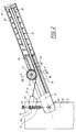
- one arranged within the swivel arm 9 and in 1 therefore shows energy storage 12 shown in dashed lines with the help of a flexible force transmission element 13 a pulley 14 on an abutment point 15 on Base part 5 directed force on the swivel arm 9.
- the abutment point 15 is in a longitudinal groove 17 of the base part 5 adjustable orthogonally to the swivel axis A1 in order to at a Weight change of the device to be carried 3 the desired to be able to restore unstable balance.
- Figure 2 leaves the location of the abutment point 15 in detail recognize and shows the energy storage arranged in the swivel arm 9 12 in a sectional view.
- the flexible force transmission element 13 has on the base part side a hinge piece 19, which on a journal 20 of the Base part 5 about a hinge axis parallel to the pivot axis A1 A4 is articulated.
- the abutment point 15 is therefore at the intersection the hinge axis A4 and the tangent to the section of the flexible power transmission element 13 between joint piece 19th and pulley 14.
- the energy store 12 includes one inside as a hollow body trained swivel arm 9 accommodated flat wire spring 21.
- the flat wire spring 21 is on one in the swivel arm 9 movable pipe 23 out and is supported with her to Pivot axis A1 near the end of an annular shoulder 25 inside of the swivel arm 9 and with its other end on a flange 27 of the tube 23.
- On the flange 27 is also as Timing belt 13 trained flexible power transmission element attached, which of the deflection roller 14 in its direction is deflected towards abutment point 15.
- the tube 23 carrying the flat wire spring 21 is over its Flange 27 from one on the inner wall of the swivel arm 9 trained slide bearing 33 and from the guide roller 14 and a pressure roller 35 guided without play.
- the deflection roller 14 is one Swivel axis A1 parallel axis 37 rotatable on the swivel arm 9 stored and has two flanges 39, which in the area the guide roller 14 semicircular cylindrical tube 23 between them record, tape.
- An about an axis of rotation 45 parallel to the axis of rotation 37 rotatably arranged pressure roller 43 urges the tube 23 against the pulley 14.
Landscapes
- Engineering & Computer Science (AREA)
- General Engineering & Computer Science (AREA)
- Mechanical Engineering (AREA)
- Microscoopes, Condenser (AREA)
- Transmission Devices (AREA)
Abstract
Description
- Figur 1
- eine schematische Darstellung eines Ausführungsbeispiels des erfindungsgemäßen Stativs in Seitenansicht;
- Figur 2
- ein Detail von Figur 1 in teilweise geschnittener Darstellung;
- Figur 3
- eine Schnittdarstellung entlang der Linie III-III von Figur 3; und
- Figur 4
- eine Figur 2 entsprechende Darstellung mit einer anderen Schwenkarmstellung.
Claims (11)
- Stativ (1) für ein bewegbar anzuordnendes Gerät (3), umfassenddadurch gekennzeichnet, daßeinen ersten Stativteil (5),einen relativ zum ersten Stativteil (5) bewegbaren zweiten Stativteil (7) mit einem an dem ersten Stativteil (5) angelenkten, um eine Schwenkachse (A1) schwenkbaren Schwenkarm (9),und einen Energiespeicher (12), welcher mittels eines Umlenkelements (14) eine auf einen Widerlagerpunkt (15) am ersten Stativteil (5) gerichtete Kraft auf den Schwenkarm (9) ausübt,
die Schwenkachse (A1) und der Widerlagerpunkt (15) stets eine Vertikalebene (16) bilden und daß das Umlenkelement (14) an dem zweiten Stativteil (7) angeordnet ist. - Stativ (1) nach Anspruch 1, dadurch gekennzeichnet, daß der Widerlagerpunkt (15) durch eine Schraubspindel (49) orthogonal zur Schwenkachse (A1) verschiebbar ist.
- Stativ (1) nach Anspruch 1 oder 2, dadurch gekennzeichnet, daß der Energiespeicher (12) eine am Schwenkarm (9) angeordnete Feder (21) umfaßt und das Umlenkelement eine am Schwenkarm (9) angeordnete Umlenkrolle (14) ist.
- Stativ (1) nach Anspruch 3, dadurch gekennzeichnet, daß die Feder eine sich schwenkachsenseitig am Schwenkarm (9) abstützende Druckfeder (21) ist, an deren schwenkachsenfernem Ende ein über die Umlenkrolle (14) zum Widerlagerpunkt (15) geführtes, flexibles Kraftübertragungselement (13) angreift.
- Stativ (1) nach Anspruch 4, dadurch gekennzeichnet, daß die Feder eine Flachdrahtfeder (21) ist.
- Stativ (1) nach Anspruch 4 oder 5, dadurch gekennzeichnet, daß die Feder (21) auf einem in dem Schwenkarm (9) verschiebbaren Rohr (23) geführt ist, dessen schwenkachsenfernes Ende mit dem flexiblen Kraftübertragungselement (13) verbunden ist.
- Stativ (1) nach Anspruch 6, dadurch gekennzeichnet, daß das Rohr (23) von der Umlenkrolle (14) und einer Andruckrolle (35) sowie einem Gleitlager (33) am Schwenkarm (9) spielfrei geführt ist.
- Stativ (1) nach einem der Ansprüche 6 oder 7, dadurch gekennzeichnet, daß das Rohr (23) federseitig eine reibungsmindernde Beschichtung aufweist.
- Stativ (1) nach einem der Ansprüche 4 bis 8, dadurch gekennzeichnet, daß das flexible Kraftübertragungselement als Zahnriemen (13) ausgebildet ist, der mit einer Verzahnung (44) der Umlenkrolle (14) kämmt.
- Stativ (1) nach Anspruch 9, dadurch gekennzeichnet, daß die Drehbeweglichkeit der am Schwenkarm (9) angeordneten Umlenkrolle (14) sperrbar ist.
- Stativ (1) nach einem der Ansprüche 3 bis 10, dadurch gekennzeichnet, daß der Schwenkarm (9) als im wesentlichen geschlossener Hohlkörper ausgebildet ist, der in seinem Inneren die Feder (21) aufnimmt.
Applications Claiming Priority (2)
| Application Number | Priority Date | Filing Date | Title |
|---|---|---|---|
| DE19711572A DE19711572B4 (de) | 1997-03-20 | 1997-03-20 | Operationsmikroskopstativ |
| DE19711572 | 1997-03-20 |
Publications (2)
| Publication Number | Publication Date |
|---|---|
| EP0866260A1 true EP0866260A1 (de) | 1998-09-23 |
| EP0866260B1 EP0866260B1 (de) | 2003-12-10 |
Family
ID=7823981
Family Applications (1)
| Application Number | Title | Priority Date | Filing Date |
|---|---|---|---|
| EP98103166A Expired - Lifetime EP0866260B1 (de) | 1997-03-20 | 1998-02-23 | Stativ |
Country Status (4)
| Country | Link |
|---|---|
| US (1) | US6070839A (de) |
| EP (1) | EP0866260B1 (de) |
| JP (1) | JP4212678B2 (de) |
| DE (2) | DE19711572B4 (de) |
Cited By (3)
| Publication number | Priority date | Publication date | Assignee | Title |
|---|---|---|---|---|
| US6523796B2 (en) | 2000-10-19 | 2003-02-25 | Carl-Zeiss-Stiftung | Pivot mounting assembly |
| US7158292B2 (en) | 2001-12-21 | 2007-01-02 | Leica Microsystems (Schweiz) Ag | Apparatus for retaining an optical viewing device |
| CN101999057A (zh) * | 2010-06-09 | 2011-03-30 | 创新办公产品公司 | 带电缆和弹簧的铰接监控器臂 |
Families Citing this family (26)
| Publication number | Priority date | Publication date | Assignee | Title |
|---|---|---|---|---|
| US6334595B1 (en) * | 1999-12-29 | 2002-01-01 | Car-O-Liner Ab | Device for supporting a hand-held tool |
| DE10042272B4 (de) * | 2000-08-29 | 2012-10-31 | Leica Instruments (Singapore) Pte. Ltd. | Stativanordnung |
| DE20019105U1 (de) | 2000-11-12 | 2001-05-23 | Leica Microsystems Ag, Heerbrugg | Stativ |
| DE20019107U1 (de) | 2000-11-12 | 2001-01-25 | Leica Microsystems Ag, Heerbrugg | Stativ |
| DE20019109U1 (de) | 2000-11-12 | 2001-02-22 | Leica Microsystems Ag, Heerbrugg | Stativ, insbesondere für Operationsmikroskope |
| DE10156318A1 (de) * | 2001-11-19 | 2003-05-28 | Zeiss Carl | Vorrichtung und Verfahren für wenigstens teilweisen Ausgleich eines Last-Drehmoments |
| US6539333B1 (en) * | 2002-01-04 | 2003-03-25 | Leica Microsystems Ag | Stand having an automatic balancing device |
| DE20204321U1 (de) | 2002-03-19 | 2002-05-29 | Leica Microsystems Ag, Heerbrugg | Federelement |
| DE10314156B9 (de) * | 2003-03-28 | 2005-05-25 | Carl Zeiss | Schwenkhalterungsanordnung und Verfahren zum Steuern einer solchen |
| AU2003258728A1 (en) * | 2003-08-05 | 2005-03-07 | Llaza, Sa | Articulated arm for awnings, with improved elastic effect |
| BE1015666A3 (nl) * | 2003-08-29 | 2005-07-05 | Brutsaert Trading Bv Met Beper | Beweegbare arm voor een parasol of dergelijke. |
| TW200739176A (en) * | 2006-04-11 | 2007-10-16 | Fulfil Tech Co Ltd | Supporting apparatus with going up-and-down |
| US7861987B2 (en) * | 2008-07-31 | 2011-01-04 | Timothy M. Horsuch | Hunting accessory holding devices |
| US8181927B2 (en) * | 2009-03-25 | 2012-05-22 | Lenovo (Singapore) Pte. Ltd. | Providing constant counterbalance throughout predetermined range of motion |
| JP2011030726A (ja) * | 2009-07-31 | 2011-02-17 | Manii Kk | 顕微鏡懸垂装置 |
| CA2712212C (en) * | 2009-08-05 | 2016-11-29 | Marcin Gawelek | Articulating mount |
| US20110266411A1 (en) * | 2010-04-29 | 2011-11-03 | David Silverberg | Ergonomically balanced and moveable arm support system |
| BR112012031282A2 (pt) | 2010-06-09 | 2016-11-01 | Innovative Office Products Inc | braço monitor de articulação com corrente e mola |
| US9061316B2 (en) * | 2011-10-28 | 2015-06-23 | Nordson Corporation | Mountable device for dispensing heated adhesive |
| EP2853798A1 (de) * | 2013-09-25 | 2015-04-01 | Brunson Instrument Company | Anordnungssystem eines Abbildungsstativs mit Vierstangenverbindung und Verfahren |
| US10845000B2 (en) * | 2016-10-21 | 2020-11-24 | Colebrook Bosson Saunders (Products) Limited | Display support system |
| WO2022118228A1 (en) * | 2020-12-03 | 2022-06-09 | Vitec Imaging Solutions S.P.A. | Balanced support head for video-photographic equipment |
| WO2022238712A1 (en) | 2021-05-12 | 2022-11-17 | Colebrook Bosson & Saunders (Products) Limited | Tilt head for high load display support system |
| DE102021121258B3 (de) | 2021-08-16 | 2022-08-11 | Carl Zeiss Meditec Ag | Haltearm für ein Stativ eines Operationsmikroskops, Verfahren zur Lagefixierung des Haltearms und Sicherungseinrichtung für den Haltearm |
| CN113524257A (zh) * | 2021-09-10 | 2021-10-22 | 深圳市资福医疗技术有限公司 | 一种重力平衡支撑臂及应用其的磁锚定设备 |
| DE102023132550A1 (de) * | 2023-11-22 | 2025-05-22 | Olympus Winter & Ibe Gmbh | Vorrichtung und Verfahren zum Halten eines medizinischen Instruments, insbesondere eines Endoskops |
Citations (5)
| Publication number | Priority date | Publication date | Assignee | Title |
|---|---|---|---|---|
| GB481198A (en) * | 1936-09-10 | 1938-03-08 | George Carwardine | Improvements in equipoising mechanism |
| GB2074337A (en) * | 1980-04-15 | 1981-10-28 | Univ Technology | Adjustable support for an optical or other instrument |
| DD221571A1 (de) | 1984-02-01 | 1985-04-24 | Zeiss Jena Veb Carl | Drehgelenk mit einer einrichtung zur kompensation unterschiedlicher lastmomente |
| DE3739080A1 (de) | 1987-11-01 | 1989-05-11 | Stemme Otto | Federvorrichtung zum gewichtausgleich fuer stative |
| US5253832A (en) * | 1991-07-26 | 1993-10-19 | Bolas Mark T | Spring counterbalanced boom suspension system |
Family Cites Families (9)
| Publication number | Priority date | Publication date | Assignee | Title |
|---|---|---|---|---|
| US1564886A (en) * | 1925-06-13 | 1925-12-08 | Thomas F O'neill | Suspension device for electric lamps |
| US2150975A (en) * | 1936-07-20 | 1939-03-21 | Aaron S Green | Instrument supporting device |
| US2398211A (en) * | 1944-06-26 | 1946-04-09 | Indian Motocycle Company | Spring suspension for saddles |
| US2502510A (en) * | 1948-02-24 | 1950-04-04 | Infra Appliances Corp | Supporting stand |
| JPS5412063B2 (de) * | 1972-07-15 | 1979-05-19 | ||
| US4659280A (en) * | 1985-01-22 | 1987-04-21 | Gmf Robotics Corporation | Robot with balancing mechanism having a variable counterbalance force |
| DE3921857A1 (de) * | 1989-07-04 | 1991-01-17 | Wild Leitz Ag | Mit zusatzvorrichtungen ausgestattetes stativ fuer die halterung eines frei positionierbaren geraetes |
| US5609316A (en) * | 1995-09-05 | 1997-03-11 | Tigliev; George S. | Suspension system for surgical microscope |
| US5746404A (en) * | 1996-02-15 | 1998-05-05 | Merko; Andrew V. | Apparatus for counterbalancing equipment |
-
1997
- 1997-03-20 DE DE19711572A patent/DE19711572B4/de not_active Expired - Lifetime
-
1998
- 1998-02-23 DE DE59810372T patent/DE59810372D1/de not_active Expired - Lifetime
- 1998-02-23 EP EP98103166A patent/EP0866260B1/de not_active Expired - Lifetime
- 1998-03-17 JP JP06641598A patent/JP4212678B2/ja not_active Expired - Lifetime
- 1998-03-20 US US09/045,485 patent/US6070839A/en not_active Expired - Lifetime
Patent Citations (5)
| Publication number | Priority date | Publication date | Assignee | Title |
|---|---|---|---|---|
| GB481198A (en) * | 1936-09-10 | 1938-03-08 | George Carwardine | Improvements in equipoising mechanism |
| GB2074337A (en) * | 1980-04-15 | 1981-10-28 | Univ Technology | Adjustable support for an optical or other instrument |
| DD221571A1 (de) | 1984-02-01 | 1985-04-24 | Zeiss Jena Veb Carl | Drehgelenk mit einer einrichtung zur kompensation unterschiedlicher lastmomente |
| DE3739080A1 (de) | 1987-11-01 | 1989-05-11 | Stemme Otto | Federvorrichtung zum gewichtausgleich fuer stative |
| US5253832A (en) * | 1991-07-26 | 1993-10-19 | Bolas Mark T | Spring counterbalanced boom suspension system |
Non-Patent Citations (1)
| Title |
|---|
| "FEINGERAETETECHNIK", vol. 2, 1965, article H. HILPERT: "Gewichtsausgleich an Feinmechanischen Geraeten", pages: 63 |
Cited By (5)
| Publication number | Priority date | Publication date | Assignee | Title |
|---|---|---|---|---|
| US6523796B2 (en) | 2000-10-19 | 2003-02-25 | Carl-Zeiss-Stiftung | Pivot mounting assembly |
| US7158292B2 (en) | 2001-12-21 | 2007-01-02 | Leica Microsystems (Schweiz) Ag | Apparatus for retaining an optical viewing device |
| CN101999057A (zh) * | 2010-06-09 | 2011-03-30 | 创新办公产品公司 | 带电缆和弹簧的铰接监控器臂 |
| WO2011155934A1 (en) * | 2010-06-09 | 2011-12-15 | Innovative Office Products, Inc. | Articulating monitor arm with cable and spring |
| CN101999057B (zh) * | 2010-06-09 | 2013-10-16 | 创新办公产品公司 | 带电缆和弹簧的铰接监控器臂 |
Also Published As
| Publication number | Publication date |
|---|---|
| JPH10267193A (ja) | 1998-10-09 |
| EP0866260B1 (de) | 2003-12-10 |
| DE59810372D1 (de) | 2004-01-22 |
| DE19711572B4 (de) | 2006-09-07 |
| US6070839A (en) | 2000-06-06 |
| JP4212678B2 (ja) | 2009-01-21 |
| DE19711572A1 (de) | 1998-09-24 |
Similar Documents
| Publication | Publication Date | Title |
|---|---|---|
| EP0866260B1 (de) | Stativ | |
| EP0983467B1 (de) | Gelenkarm für bürogeräte | |
| EP1538386B1 (de) | Stativ | |
| EP2057338B1 (de) | Möbelscharnier | |
| DE2954140C2 (de) | Einhak- und Festsetzvorrichtung für Lasten unter Flugzeugen | |
| AT502487A4 (de) | Dämpferanordnung | |
| DE2952078C2 (de) | Einrichtung zur spielfreien Kurvensteuerung | |
| EP2246006A2 (de) | Operations-Assistenz-System | |
| DE3211372C2 (de) | ||
| DE69201691T2 (de) | Mobiles Röntgengerät. | |
| DE19742050B4 (de) | Stativ mit Gewichtsausgleich | |
| DE19742051B4 (de) | Stativ mit Energiespeicher zum Gewichtsausgleich | |
| WO2002053965A1 (de) | Kamerastativkopf mit gewichtsausgleich | |
| EP1853136B1 (de) | Verstellbares sitzmöbel | |
| CH692926A5 (de) | Stativ mit Energiespeicher zum Gewichtsausgleich. | |
| EP3822682A2 (de) | Fernrohr und fokussiervorrichtung | |
| EP1253994B1 (de) | Spanneinrichtung | |
| DD208871A1 (de) | Fokussieranordnung fuer spiegelteleskope | |
| AT526950B1 (de) | Führungsanordnung zur Führung eines bewegbaren Möbelteils | |
| AT526953B1 (de) | Führungsanordnung zur Führung eines bewegbaren Möbelteils | |
| AT526422B1 (de) | Anordnung zur Bewegung wenigstens eines Abdeckelements | |
| WO2000059753A1 (de) | Verstellvorrichtung | |
| EP0846504A1 (de) | Walzgerüst-Exzenterlagerhülsen für Walzentragwellen | |
| EP0979063A2 (de) | Therapie-und trainingsgerat zur zwanggefürhten kniegelenkbewegung | |
| DE19742049B4 (de) | Stativ mit Seilparallelogramm |
Legal Events
| Date | Code | Title | Description |
|---|---|---|---|
| PUAI | Public reference made under article 153(3) epc to a published international application that has entered the european phase |
Free format text: ORIGINAL CODE: 0009012 |
|
| AK | Designated contracting states |
Kind code of ref document: A1 Designated state(s): CH DE FR GB IT LI |
|
| AX | Request for extension of the european patent |
Free format text: AL;LT;LV;MK;RO;SI |
|
| 17P | Request for examination filed |
Effective date: 19981012 |
|
| AKX | Designation fees paid |
Free format text: CH DE FR GB IT LI |
|
| RBV | Designated contracting states (corrected) |
Designated state(s): CH DE FR GB IT LI |
|
| 17Q | First examination report despatched |
Effective date: 20020911 |
|
| GRAH | Despatch of communication of intention to grant a patent |
Free format text: ORIGINAL CODE: EPIDOS IGRA |
|
| GRAS | Grant fee paid |
Free format text: ORIGINAL CODE: EPIDOSNIGR3 |
|
| GRAA | (expected) grant |
Free format text: ORIGINAL CODE: 0009210 |
|
| AK | Designated contracting states |
Kind code of ref document: B1 Designated state(s): CH DE FR GB IT LI |
|
| REG | Reference to a national code |
Ref country code: GB Ref legal event code: FG4D Free format text: NOT ENGLISH |
|
| REG | Reference to a national code |
Ref country code: CH Ref legal event code: EP |
|
| REF | Corresponds to: |
Ref document number: 59810372 Country of ref document: DE Date of ref document: 20040122 Kind code of ref document: P |
|
| GBT | Gb: translation of ep patent filed (gb section 77(6)(a)/1977) |
Effective date: 20040315 |
|
| ET | Fr: translation filed | ||
| PLBE | No opposition filed within time limit |
Free format text: ORIGINAL CODE: 0009261 |
|
| STAA | Information on the status of an ep patent application or granted ep patent |
Free format text: STATUS: NO OPPOSITION FILED WITHIN TIME LIMIT |
|
| 26N | No opposition filed |
Effective date: 20040913 |
|
| REG | Reference to a national code |
Ref country code: FR Ref legal event code: PLFP Year of fee payment: 19 |
|
| REG | Reference to a national code |
Ref country code: FR Ref legal event code: PLFP Year of fee payment: 20 |
|
| PGFP | Annual fee paid to national office [announced via postgrant information from national office to epo] |
Ref country code: CH Payment date: 20170217 Year of fee payment: 20 Ref country code: FR Payment date: 20170217 Year of fee payment: 20 Ref country code: DE Payment date: 20170217 Year of fee payment: 20 |
|
| PGFP | Annual fee paid to national office [announced via postgrant information from national office to epo] |
Ref country code: GB Payment date: 20170216 Year of fee payment: 20 |
|
| PGFP | Annual fee paid to national office [announced via postgrant information from national office to epo] |
Ref country code: IT Payment date: 20170221 Year of fee payment: 20 |
|
| REG | Reference to a national code |
Ref country code: DE Ref legal event code: R071 Ref document number: 59810372 Country of ref document: DE |
|
| REG | Reference to a national code |
Ref country code: CH Ref legal event code: PL |
|
| REG | Reference to a national code |
Ref country code: GB Ref legal event code: PE20 Expiry date: 20180222 |
|
| PG25 | Lapsed in a contracting state [announced via postgrant information from national office to epo] |
Ref country code: GB Free format text: LAPSE BECAUSE OF EXPIRATION OF PROTECTION Effective date: 20180222 |