EP0866271A2 - Apparat und Verfahren zur Rückgewinnung von Abgaswärme in einer Wirbelschichtmüllverbrennungsanlage und Verfahren zur Verhinderung der Dioxinbildung - Google Patents
Apparat und Verfahren zur Rückgewinnung von Abgaswärme in einer Wirbelschichtmüllverbrennungsanlage und Verfahren zur Verhinderung der Dioxinbildung Download PDFInfo
- Publication number
- EP0866271A2 EP0866271A2 EP97122209A EP97122209A EP0866271A2 EP 0866271 A2 EP0866271 A2 EP 0866271A2 EP 97122209 A EP97122209 A EP 97122209A EP 97122209 A EP97122209 A EP 97122209A EP 0866271 A2 EP0866271 A2 EP 0866271A2
- Authority
- EP
- European Patent Office
- Prior art keywords
- incinerator
- heat transfer
- transfer tubes
- fluid
- heat
- Prior art date
- Legal status (The legal status is an assumption and is not a legal conclusion. Google has not performed a legal analysis and makes no representation as to the accuracy of the status listed.)
- Granted
Links
Images


Classifications
-
- F—MECHANICAL ENGINEERING; LIGHTING; HEATING; WEAPONS; BLASTING
- F23—COMBUSTION APPARATUS; COMBUSTION PROCESSES
- F23G—CREMATION FURNACES; CONSUMING WASTE PRODUCTS BY COMBUSTION
- F23G5/00—Incineration of waste; Incinerator constructions; Details, accessories or control therefor
- F23G5/44—Details; Accessories
- F23G5/46—Recuperation of heat
-
- F—MECHANICAL ENGINEERING; LIGHTING; HEATING; WEAPONS; BLASTING
- F23—COMBUSTION APPARATUS; COMBUSTION PROCESSES
- F23G—CREMATION FURNACES; CONSUMING WASTE PRODUCTS BY COMBUSTION
- F23G5/00—Incineration of waste; Incinerator constructions; Details, accessories or control therefor
- F23G5/30—Incineration of waste; Incinerator constructions; Details, accessories or control therefor having a fluidised bed
-
- F—MECHANICAL ENGINEERING; LIGHTING; HEATING; WEAPONS; BLASTING
- F23—COMBUSTION APPARATUS; COMBUSTION PROCESSES
- F23J—REMOVAL OR TREATMENT OF COMBUSTION PRODUCTS OR COMBUSTION RESIDUES; FLUES
- F23J7/00—Arrangement of devices for supplying chemicals to fire
-
- F—MECHANICAL ENGINEERING; LIGHTING; HEATING; WEAPONS; BLASTING
- F23—COMBUSTION APPARATUS; COMBUSTION PROCESSES
- F23J—REMOVAL OR TREATMENT OF COMBUSTION PRODUCTS OR COMBUSTION RESIDUES; FLUES
- F23J2215/00—Preventing emissions
- F23J2215/30—Halogen; Compounds thereof
- F23J2215/301—Dioxins; Furans
Definitions
- the present invention relates to an apparatus and a method for recovering heat generated during the incineration of combustible wastes, such as city garbage containing incombustible matters, waste plastics and industrial wastes, in a fluid-bed type incinerator, and a method for inhibiting resynthesis of detrimental dioxins occurring in a combustion waste gas discharged from the incinerator.
- combustible wastes such as city garbage containing incombustible matters, waste plastics and industrial wastes
- a fluid layer of sand particles and the like as a fluid medium is formed in a lower portion of the incinerator.
- Combustible wastes charged into the incinerator are burnt while being fluidized together with the sand particles which have been previously heated to a prescribed temperature, in the fluid layer.
- An air chamber is provided on a bottom of the fluid-bed type incinerator. Air blown into the air chamber from a blower is ejected upward from the air chamber into the incinerator through an air dispersing plate such as a porous plate, and the thus ejected air fluidizes the fluid medium such as sand particles, thereby forming the fluid layer. In the fluid layer, the fluid medium moves up and down to form a fluidized state.
- a combustion waste gas produced from the combustion of the wastes is, on the other hand, introduced through a flue into a dust collector, in which dust contained in the combustion waste gas is collected.
- combustible wastes such as city garbage and industrial wastes are charged through a waste charging port (not shown) provided on the upper portion of a fluid-bed type incinerator 1 into a fluid layer 2 kept at substantially a uniform temperature.
- the charged wastes are burnt while being fluidized together with the sand particles as a fluid medium, in the fluid layer 2.
- Incombustible matters contained in the wastes to be incinerated are transferred outside the incinerator through an incombustible matter discharge port (not shown) provided on the bottom of the incinerator 1.
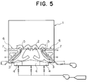
- Slant partitions 5 are provided above an upper portion of an air chamber 4 positioned near an incinerator side wall, of the air chamber 4 partitioned into a plurality of cells. Under the effect of the slant partitions 5, air for fluidizing the fluid medium is reflected toward the center of the incinerator 1. As a result, a rotary flow 3 is produced in the fluid layer of the fluid medium as shown by a large arrow in Fig. 5.
- a heat recovering chamber 6 partitioned by them is formed, and plurality of heat transfer tubes 7 are inserted horizontally from the incinerator side wall toward the slant partition 5.
- a part of the fluid medium forming the fluid layer 2 passes over the slant partition 5 and enters the heat recovering chamber 6.
- heat of the fluid medium is recovered by means of the heat transfer tubes 7.
- the fluid medium after being recovered heat, circulates again to the center portion of the incinerator 1 and is incorporated into the rotary flow 3.
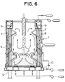
- a plurality of straight heat transfer tubes 7 are substantially vertically arranged in a heat recovering chamber 6 of a fluid-bed type incinerator 1 along a side wall thereof.
- An upper portion and a lower portion of each of the plurality of heat transfer tubes 7 are connected to an upper water chamber 9 and a lower water chamber 10, respectively.
- the upper water chamber 9, the heat transfer tubes 7 and the lower water chamber 10 communicate with each other.
- the prior art 2 discloses a heat recovering apparatus in which a plurality of heat transfer tubes are inserted horizontally from the incinerator side wall horizontally into the incinerator, as in the apparatus of the prior art 1 shown in Fig. 5.
- a combustion waste gas produced during the combustion of wastes is introduced through a flue into a dust collector, and after the collection of dust and the like, diffused to the open air.
- the combustion waste gas produced during the combustion of wastes in the incinerator contains dioxins having a strong toxicity though in a slight amount, which include polychlorinated dibenzo-p-dioxin and polychlorinated dibenzofuran. Inhibition of the production of these dioxins is now an important problem.
- Japanese Patent Publication No. JP-B-61-24,606 discloses a method for removing hydrogen chloride contained in a combustion waste gas discharged from an incinerator, which comprises the step of: when forming a fluid layer comprising inert particles in an incinerator to burn wastes in said fluid layer, adding granular dolomite containing particles having a particle size of from about 2 to 5 mm in an amount of at least about 80 wt.% into the incinerator, thereby removing hydrogen chloride in a combustion waste gas (hereinafter referred to as the "prior art 5").
- the prior art 5 discloses a method for removing hydrogen chloride in a combustion waste gas by adding granular dolomite containing particles having a particles size of from about 2 to 5 mm, but discloses nothing about inhibition of production of dioxins.
- An object of the present invention is therefore to overcome the problems in the above-mentioned prior arts and to provide an apparatus and a method for recovering heat generated in a fluid-bed type incinerator during the incineration of combustible wastes such as industrial wastes in the incinerator, which apparatus and method permit the performance of replacement operation of a plurality of heat transfer tubes safely in a short period of time without causing incombustible matters in the wastes to cling to the heat transfer tubes, as well as a method for inhibiting the production of dioxins, which enables to inhibit the resynthesis of dioxins in a flue running from the incinerator to the dust collector, while a combustion waste gas discharged from a combustion waste gas discharge port of the incinerator, is introduced through the flue into the dust collector for collecting dust.
- a method for recovering heat from an incinerator which comprises the steps of:
- an apparatus for recovering heat from an incinerator in which a plurality of heat transfer tubes are arranged in a peripheral portion of a fluid layer of a fluid-bed type incinerator, and heat generated from combustion of an object to be incinerated in said fluid layer is recovered via a heat receiving medium flowing through said plurality of heat transfer tubes; characterized in that:
- said plurality of heat transfer tubes comprise unit heat transfer tubes.
- a method for recovering heat from an incinerator and inhibiting production of dioxins which comprises the steps of:
- each of the heat transfer tubes in contact with the fluid layer containing incombustible matters does not have a horizontal portion except for the bent tube portion forming the lower portion of the heat transfer tube, the moving direction of a fluid medium moving only up and down agrees with the axial direction of the heat transfer tube, thus permitting prevention of incombustible matters from clinging to the heat transfer tubes.
- the present invention was made on the basis of the foregoing findings, and the method of the present invention for recovering heat from an incinerator comprises the steps of:
- the apparatus of the present invention for recovering heat from an incinerator, in which a plurality of heat transfer tubes are arranged in a peripheral portion of a fluid layer of a fluid-bed type incinerator, and heat generated from combustion of an object to be incinerated in said fluid layer is recovered via a heat receiving medium flowing through said plurality of heat transfer tubes, is characterized in that:
- said plurality of heat transfer tubes comprise unit heat transfer tubes.
- the method of the present invention for recovering heat from an incinerator and inhibiting production of dioxins comprises the steps of:
- each of the plurality of heat transfer tubes comprises a U-shaped heat transfer tube which has two vertical tube portions, and a bent tube portion having both ends thereof communicating with the respective vertical tube portions, and the plurality of heat transfer tubes are removably arranged in the vertical direction in the incinerator from a wall thereof.
- the plurality of heat transfer tubes may comprise unit heat transfer tubes.
- a heat receiving medium flows downward from above an upper incinerator wall in one of the vertical tube portions, and after reaching the bent tube portion located in a fluid layer of the incinerator, flows upward in the other of the vertical tube portions.
- the heat receiving medium then flows out to above the upper incinerator wall.
- the heat receiving medium can therefore efficiently recover heat of the high-temperature fluid layer.
- each of the heat transfer tubes in contact with the fluid layer containing incombustible matters does not have a horizontal portion except for the bent tube portion forming the lower portion of the heat transfer tube, the moving direction of the fluid medium moving only up and down agrees with the axial direction of the heat transfer tube.
- the incombustible matters never cling to the heat transfer tubes, thus permitting smooth recovery of heat from the fluid layer while keeping the fluid layer in a satisfactory state. Further, there is present a very short horizontal portion in the bent tube portion of the heat transfer tube. However, because the gap between the downward vertical tube portion and the upward vertical tube portion is very small, the bent tube portion of the heat transfer tube is almost free from clogging of incombustible matters.
- connecting portions of the plurality of heat transfer tubes provided on the incinerator wall are above the fluid layer (i.e., in the present invention, the heat transfer tubes are vertically attached and removed from the incinerator wall located above the fluid layer), it is not necessary to remove the fluid medium from the incinerator upon replacing the heat transfer tubes, thus permitting replacement of the heat transfer tubes in a short period of time. Even when the heat transfer tubes are removed from the incinerator wall, the replacing operation of the heat transfer tubes can be safely carried out without splash of the high-temperature fluid medium to outside the incinerator, because the connecting portions of the heat transfer tubes are located above the fluid layer as described above.
- the heat transfer tubes can be more efficiently replaced.
- the production of dioxins in the incinerator is inhibited by appropriately adjusting the combustion conditions, i.e., the combustion temperature, the gas staying time and the gas turbulence condition, as set forth in the Guideline established by the Ministry of Health and Welfare.
- a calcium compound such as limestone (CaCO 3 ) and slaked lime (Ca(OH) 2 ) having a particle size of up to 500 ⁇ m is supplied into the incinerator.
- the supplied calcium compound having a particle size of up to 500 ⁇ m is introduced into a flue from the incinerator together with a combustion waste gas, and convert hydrogen chloride (HCl) present in the combustion waste gas flowing through the flue and causing the production of dioxins, into innoxious calcium chloride (CaCl 2 ) through a reaction expressed by the following formulae: CaCO 3 ⁇ CaO + CO 2 Ca(OH) 2 ⁇ CaO + H 2 O CaO + 2HCl ⁇ CaCl 2 + H 2 O
- the innoxious calcium chloride (CaCl 2 ) produced from the foregoing reaction is collected in a dust collector and removed. During the time in which the combustion waste gas discharged from the incinerator passes through the flue and reaches the dust collector, therefore, resynthesis of dioxins is certainly inhibited.
- the particle size of the calcium compound to be supplied into the incinerator should therefore be up to 500 ⁇ m. From the point of view of manufacture or handling, the particle size of the calcium compound should preferably be at least 100 ⁇ m.
- the amount of supplied calcium compound should preferably be at least 2 in a molar ratio of Ca/(1/2 Cl).
- sulfur (S) is contained in the wastes to be incinerated, the amount of supplied calcium compound should preferably be at least 2 in a molar ratio of Ca/(1/2 Cl + S) , taking account of the amount of the calcium compound to be consumed in a reaction between sulfur and the calcium compound as represented by the following formula: CaO + SO 2 - CaSO 4
- the molar ratio of Ca/(1/2 Cl) or Ca/(1/2 Cl + S) should therefore preferably be up to 10.
- the calcium compound may previously be mixed in the wastes to be incinerated to supply same together with the wastes into the incinerator, or may be supplied separately from the wastes into the incinerator.
- Fig. 1 is a schematic sectional view illustrating a first embodiment of the apparatus of the present invention for recovering heat from a fluid-bed type incinerator.
- a fluid-bed type incinerator 11 equipped with the apparatus of the first embodiment for recovering heat, the incineration of wastes, the recovery of heat and the replacement of a plurality of heat transfer tubes were carried out.
- a horizontal incinerator wall 13 having holes (not shown) is formed on the incinerator wall surrounding a free board section 12 of the fluid-bed type incinerator 11, and a plurality of U-shaped heat transfer tubes 14 are vertically inserted into the incinerator 11 through the holes piercing the horizontal incinerator wall 13.
- the plurality of heat transfer tubes 14 are inserted into the incinerator 11 so that a bent tube portion 20 of each heat transfer tube 14 is immersed in a fluid layer 15 to be formed by a fluid medium such as sand particles.
- Each heat transfer tube 14 comprises two horizontal tube portions 18 connected respectively to an entry header 16 and an exit header 17, two vertical tube portions 19 extending vertically from the respective horizontal tube portions 18, and a U-shaped bent tube portion 20 having both ends thereof communicating with the respective vertical tube portions 19.
- each heat transfer tube 14 flows, as shown by an arrow in Fig. 1, from the entry header 16 through one of the horizontal tube portions 18 outside the incinerator 11 into one of the vertical tube portions 19 in the incinerator 11, flows downward through the one of the vertical tube portions 19, flows upward through the other of the vertical tube portions 19 via the lowermost bent tube portion 20, and flows out into the exit header 17 through the other of the horizontal tube portions 18.
- 21 is an air dispersing plate
- 22 is an air chamber partitioned into a plurality of cells
- 23 is an incombustible matter discharge port.
- Sand particles serving as the fluid medium are fluidized by means of air ejected from the air chamber 22 through the air dispersing plate 21 provided on the bottom of the incinerator 11 to form the fluid layer 15.
- Combustible wastes such as city garbage, waste plastics and industrial wastes are charged into the thus formed fluid layer 15 to incinerate the wastes.
- the plurality of heat transfer tubes 14 are vertically inserted into the incinerator 11 from the horizontal incinerator wall 13 above the fluid layer 15 as described above. Steam serving as the heat receiving medium first flows downward toward the lowermost portion of each heat transfer tube from the horizontal incinerator wall 13, and after reaching the lowermost bent tube portion 20, flows again upward to flow out from the horizontal incinerator wall 13.
- the plurality of heat transfer tubes 14 are immersed vertically into the fluid layer 15. Motion of the sand particles as the fluid medium moving up and down is therefore never prevented. As a result, a satisfactory fluidized state of the fluid layer 15 could be maintained. Further, incombustible matters in the fluid layer 15 never clinged to the heat transfer tubes 14.
- Replacement of the plurality of heat transfer tubes 14 could easily be accomplished, by releasing the joint between the horizontal incinerator wall 13 of the incinerator 11 and the heat transfer tubes 14, pulling out the heat transfer tubes 14 upward from the incinerator 11, and inserting new heat transfer tubes into the incinerator 11.
- heat could efficiently recovered from the fluid layer 15 of the incinerator 11. Further, upon replacing the plurality of heat transfer tubes 14, it was not necessary to discharge the sand particles as the fluid medium to outside the incinerator 11. Even after the completion of the replacing operation of the heat transfer tubes 14, therefore, the fluid layer 15 kept a sufficient temperature necessary for burning combustible wastes. As a result, after the completion of the replacing operation of the heat transfer tubes 14, the operation of the incinerator 11 could immediately be restarted.
- Fig. 2 is a schematic sectional view illustrating a second embodiment of the apparatus of the present invention for recovering heat from a fluid-bed type incinerator.
- a fluid-bed type incinerator 11 equipped with the apparatus of the second embodiment for recovering heat, the incineration of wastes, the recovery of heat and the replacement of the plurality of heat transfer tubes were carried out.
- unit heat transfer tubes 25 are used .
- the unit heat transfer tubes 25 comprise a connector 24, of which the interior is partitioned into prescribed shapes, and a plurality of U-shaped heat transfer tubes 14, of which the both ends communicate with the connector 24.
- the plurality of heat transfer tubes 14 are integrated into one by means of the connector 24.
- Fig. 2 12 is a free board section; 21 is an air dispersing plate; 22 is an air chamber partitioned into a plurality of cells, and 23 is an incombustible matter discharge port.
- the number of the heat transfer tubes 14 in the unit heat transfer tubes 25 is determined within a range of from two to several hundred in an incinerator having a capacity within a range of from 24 to 300 tons/day, in response to a heat quantity to be recovered from the fluid layer 15 of the incinerator 11, and a position for insertion of the unit heat transfer tubes 25.
- heat could efficiently be recovered from the fluid layer 15 of the incinerator 11. Further, upon replacing the unit heat transfer tubes 25, it was not necessary to discharge the sand particles serving as the fluid medium to outside the incinerator 11. As a result, even after the completion of the replacing operation of the unit heat transfer tubes 25, the fluid layer 15 kept a sufficient temperature necessary for burning combustible wastes. After the completion of the replacing operation of the unit heat transfer tubes 25, therefore, the incinerator 11 could immediately be restarted.
- Fig. 3 is a schematic sectional view illustrating a third embodiment of the apparatus of the present invention for recovering heat from a fluid-bed type incinerator.
- the apparatus of the third embodiment has substantially the same fundamental structure as that of the apparatus of the second embodiment shown in Fig. 2 except that a slant incinerator wall 26 is adopted in place of the horizontal incinerator wall 13 in the second embodiment.
- a slant incinerator wall 26 is provided above the fluid layer 15 of the incinerator 11, as shown in Fig. 3.
- the reason is as follows: when combustible wastes are burnt in the fluid layer 15 with the lowest possible oxygen concentration for the purpose of controlling the oxidized atmosphere and the reduced atmosphere in the incinerator 11 upon burning wastes in the fluid layer 15, unburnt gases having a high calorific value are produced in a large quantity from the fluid layer 15.
- the inclination angle of the slant incinerator wall 26 can be varied between the horizontal and 45°. With an inclination angle of over 45°, the number of heat transfer tubes 14 capable of being inserted into the fluid layer 15 decreases, so that it becomes difficult to sufficiently recover heat from the fluid layer 15. When it suffices for the quantity of recovered heat to be small, however, the inclination angle may be over 45°.
- unit heat transfer tube 25 are used as in the second embodiment. More specifically, the unit heat transfer tubes 25 comprise a connector 24, of which the interior is partitioned into prescribed shapes, and a plurality of U-shaped heat transfer tubes 14 of which the both ends communicate with the connector 24. That is, in the unit heat transfer tubes 25, the plurality of heat transfer tubes 14 are integrated into one by means of the connector 24.
- Fig. 3 12 is a free board section; 21 is an air dispersing plate; 22 is an air chamber partitioned into a plurality of cells; and 23 is an incombustible matter discharge port.
- Fig. 4 is a conceptural view illustrating a method of the present invention for inhibiting production of dioxins in a fluid-bed type incinerator.
- Silica sand particles serving as a fluid medium are placed on an air dispersing plate 32 provided in a fluid-bed type incinerator 31.
- the silica sand particles are fluidized by means of air blown upward from below the air dispersing plate 32 into the incinerator 31.
- 33 is a waste charger into the incinerator 31
- 34 is a calcium compound supplier into the incinerator 31.
- the wastes charged into the incinerator 31 by the waste charger 33 are stirred, dried and burnt by means of the fluid medium in the fluid layer, which have previously been heated to a prescribed temperature by the use of a heater (not shown).
- the combustion waste gas is discharged from a combustion waste gas discharge port 35 into a flue 36, and flows into a bag filter 37 serving as a dust collector through a waste gas inlet 38.
- the combustion waste gas of which dust has been removed by means of the bag filter 37 is released to the open air from a waste gas outlet 39.
- the concentration of hydrogen chloride in the combustion waste gas at the combustion waste gas discharge port 35 of the incinerator 31 was higher in the example of the invention No. 1, in which limestone as the calcium compound having a particle size of up to 500 ⁇ m within the scope of the present invention was supplied, than in the example for comparison No. 1, in which limestone having a particle size of from 1,000 to 2,000 ⁇ m outside the scope of the present invention was supplied into the incinerator 31.
Landscapes
- Engineering & Computer Science (AREA)
- Mechanical Engineering (AREA)
- General Engineering & Computer Science (AREA)
- Fluidized-Bed Combustion And Resonant Combustion (AREA)
Applications Claiming Priority (3)
| Application Number | Priority Date | Filing Date | Title |
|---|---|---|---|
| JP06472197A JP3391211B2 (ja) | 1997-03-18 | 1997-03-18 | 流動層熱回収装置 |
| JP64721/97 | 1997-03-18 | ||
| JP6472197 | 1997-03-18 |
Publications (3)
| Publication Number | Publication Date |
|---|---|
| EP0866271A2 true EP0866271A2 (de) | 1998-09-23 |
| EP0866271A3 EP0866271A3 (de) | 1999-07-21 |
| EP0866271B1 EP0866271B1 (de) | 2002-07-10 |
Family
ID=13266311
Family Applications (1)
| Application Number | Title | Priority Date | Filing Date |
|---|---|---|---|
| EP97122209A Expired - Lifetime EP0866271B1 (de) | 1997-03-18 | 1997-12-16 | Apparat und Verfahren zur Rückgewinnung von Abgaswärme in einer Wirbelschichtverbrennungsanlage und Verfahren zur Verhinderung der Dioxinbildung |
Country Status (5)
| Country | Link |
|---|---|
| EP (1) | EP0866271B1 (de) |
| JP (1) | JP3391211B2 (de) |
| KR (2) | KR100295625B1 (de) |
| DE (1) | DE69713872T2 (de) |
| DK (1) | DK0866271T3 (de) |
Cited By (4)
| Publication number | Priority date | Publication date | Assignee | Title |
|---|---|---|---|---|
| EP1004346A1 (de) * | 1998-11-25 | 2000-05-31 | Nobushige Maeda | Mittel zur Unterdrückung von Dioxinbildung, Verfahren zu seiner Herstellung und Verfahren zur Unterdrückung von Dioxinbildung |
| WO2003090906A1 (fr) * | 2002-04-24 | 2003-11-06 | Research Center For Eco-Environmental Sciences, Chinese Academy Of Sciences | Procede d'elimination de dioxines dans des fumees d'incinerateur |
| CN107084398A (zh) * | 2017-05-19 | 2017-08-22 | 天津辰创环境工程科技有限责任公司 | 一种处理多种废气废液的两段式l型焚烧炉 |
| DE102017122970A1 (de) * | 2017-10-04 | 2019-04-04 | FischerteC GmbH | Verbrennungsofen |
Families Citing this family (1)
| Publication number | Priority date | Publication date | Assignee | Title |
|---|---|---|---|---|
| JP5805360B2 (ja) * | 2009-04-14 | 2015-11-04 | 旭化成ケミカルズ株式会社 | 気相反応方法及び気相反応装置 |
Citations (3)
| Publication number | Priority date | Publication date | Assignee | Title |
|---|---|---|---|---|
| JPS6124606B2 (de) | 1979-02-06 | 1986-06-11 | Ebara Mfg | |
| JPH0666417A (ja) | 1992-08-13 | 1994-03-08 | Mitsubishi Heavy Ind Ltd | 塩素含有可燃物ダイオキシン類発生抑制燃焼法 |
| JPH08189627A (ja) | 1995-01-12 | 1996-07-23 | Kobe Steel Ltd | 流動層熱回収装置 |
Family Cites Families (7)
| Publication number | Priority date | Publication date | Assignee | Title |
|---|---|---|---|---|
| US3013773A (en) * | 1954-10-11 | 1961-12-19 | Sinclair Refining Co | Heat exchange apparatus |
| DE1245544B (de) * | 1966-12-08 | 1967-07-27 | Gi Proekt Zd Ov Osnovnoi Khim | Vorrichtung zur Kuehlung der Wirbelschicht in Roestoefen mit natuerlichem Kuehlmittelumlauf |
| US4380154A (en) | 1981-06-23 | 1983-04-19 | Thermacore, Inc. | Clean coal power system |
| DE3443722A1 (de) * | 1984-11-30 | 1986-06-12 | Foerster Guenther | Verfahren zur thermischen beseitigung von halogenverbindungen, insbesondere dioxine, phosgen und polychlorierte biphenyle bildende chlorverbindungen enthaltenden abfaellen sowie wirbelschicht-reaktor zu seiner durchfuehrung |
| DE3523653A1 (de) * | 1985-07-02 | 1987-02-12 | Bbc Brown Boveri & Cie | Wirbelschichtreaktor |
| US4883115A (en) * | 1988-09-16 | 1989-11-28 | Ogden Environmental Services, Inc. | Method and apparatus for cooling high-temperature processes |
| FR2668815B1 (fr) * | 1990-11-02 | 1993-04-09 | Chauffe Cie Gle | Procede d'incineration de dechets urbains dans une unite comportant un foyer a lit fluidise et une chaudiere, avec epuration intrinseque des fumees. |
-
1997
- 1997-03-18 JP JP06472197A patent/JP3391211B2/ja not_active Expired - Fee Related
- 1997-12-16 DK DK97122209T patent/DK0866271T3/da active
- 1997-12-16 DE DE69713872T patent/DE69713872T2/de not_active Expired - Fee Related
- 1997-12-16 EP EP97122209A patent/EP0866271B1/de not_active Expired - Lifetime
- 1997-12-17 KR KR1019970070196A patent/KR100295625B1/ko not_active Expired - Fee Related
-
2000
- 2000-10-05 KR KR1020000058433A patent/KR100338052B1/ko not_active Expired - Fee Related
Patent Citations (3)
| Publication number | Priority date | Publication date | Assignee | Title |
|---|---|---|---|---|
| JPS6124606B2 (de) | 1979-02-06 | 1986-06-11 | Ebara Mfg | |
| JPH0666417A (ja) | 1992-08-13 | 1994-03-08 | Mitsubishi Heavy Ind Ltd | 塩素含有可燃物ダイオキシン類発生抑制燃焼法 |
| JPH08189627A (ja) | 1995-01-12 | 1996-07-23 | Kobe Steel Ltd | 流動層熱回収装置 |
Cited By (6)
| Publication number | Priority date | Publication date | Assignee | Title |
|---|---|---|---|---|
| EP1004346A1 (de) * | 1998-11-25 | 2000-05-31 | Nobushige Maeda | Mittel zur Unterdrückung von Dioxinbildung, Verfahren zu seiner Herstellung und Verfahren zur Unterdrückung von Dioxinbildung |
| WO2003090906A1 (fr) * | 2002-04-24 | 2003-11-06 | Research Center For Eco-Environmental Sciences, Chinese Academy Of Sciences | Procede d'elimination de dioxines dans des fumees d'incinerateur |
| CN107084398A (zh) * | 2017-05-19 | 2017-08-22 | 天津辰创环境工程科技有限责任公司 | 一种处理多种废气废液的两段式l型焚烧炉 |
| CN107084398B (zh) * | 2017-05-19 | 2023-06-27 | 天津辰创环境工程科技有限责任公司 | 一种处理多种废气废液的两段式l型焚烧炉 |
| DE102017122970A1 (de) * | 2017-10-04 | 2019-04-04 | FischerteC GmbH | Verbrennungsofen |
| DE102017122970B4 (de) | 2017-10-04 | 2021-10-21 | FischerteC GmbH | Verbrennungsofen |
Also Published As
| Publication number | Publication date |
|---|---|
| EP0866271B1 (de) | 2002-07-10 |
| DE69713872D1 (de) | 2002-08-14 |
| KR100338052B1 (ko) | 2002-05-24 |
| DE69713872T2 (de) | 2003-03-13 |
| JP3391211B2 (ja) | 2003-03-31 |
| KR100295625B1 (ko) | 2001-08-07 |
| JPH10259901A (ja) | 1998-09-29 |
| DK0866271T3 (da) | 2002-10-28 |
| EP0866271A3 (de) | 1999-07-21 |
| KR19980079531A (ko) | 1998-11-25 |
Similar Documents
| Publication | Publication Date | Title |
|---|---|---|
| JP5361449B2 (ja) | 循環型流動層炉、及び循環型流動層炉の運転方法 | |
| EP0597458B1 (de) | Wirbelschicht-Müllverbrennungsanlage | |
| US5443022A (en) | Fluidized bed reactor and method utilizing refuse derived fuel | |
| CA2013010C (en) | Sludge incineration in single-stage combustor with gas scrubbing followed by afterburning and heat recovery | |
| EP0866271B1 (de) | Apparat und Verfahren zur Rückgewinnung von Abgaswärme in einer Wirbelschichtverbrennungsanlage und Verfahren zur Verhinderung der Dioxinbildung | |
| EP0687855B1 (de) | Zirkulierender Wirbelschichtreaktor für minderwertige Brennstoffe | |
| JP3276273B2 (ja) | 廃棄物の焼却熱を利用した過熱蒸気製造装置 | |
| JP2769964B2 (ja) | 塩素含有廃棄物の焼却方法及び装置 | |
| FI89074C (fi) | Foerfarande och anordning foer foergasning eller foerbraenning av fast kolhaltigt material | |
| JP4157519B2 (ja) | 循環流動層ボイラ装置 | |
| JP3757032B2 (ja) | 廃棄物の熱分解溶融燃焼装置 | |
| TWI391610B (zh) | 循環型流體化床爐、具備循環型流體化床爐的處理系統、及循環型流體化床爐的運轉方法 | |
| JP2748216B2 (ja) | 塩化物除去機能を備えた流動層ごみ焼却炉 | |
| KR100686441B1 (ko) | 연소로 출구 온도제어장치가 구비된 순환유동층 연소장치및 연소로 출구 온도제어방법 | |
| JP3174527B2 (ja) | 廃棄物の焼却方法 | |
| EP0381195B1 (de) | Veraschungsofen | |
| JP3268214B2 (ja) | 廃棄物の焼却熱を利用した過熱蒸気製造装置 | |
| JPH0335930Y2 (de) | ||
| JP2003042422A (ja) | 廃棄物燃焼方法 | |
| JP3459758B2 (ja) | 廃棄物の熱分解燃焼溶融装置 | |
| JPH0771731A (ja) | 2炉式流動層焼却炉 | |
| JPH0771735A (ja) | 微粉脱塩剤供給機能を備えた2段流動層ごみ焼却炉 | |
| JPH0960847A (ja) | ごみ焼却による過熱蒸気発生方法及び装置 | |
| JPH06129623A (ja) | 流動床焼却炉の操業方法 | |
| JPH109550A (ja) | 廃棄物焼却炉からのダイオキシン類生成抑制方法 |
Legal Events
| Date | Code | Title | Description |
|---|---|---|---|
| PUAI | Public reference made under article 153(3) epc to a published international application that has entered the european phase |
Free format text: ORIGINAL CODE: 0009012 |
|
| 17P | Request for examination filed |
Effective date: 19980113 |
|
| AK | Designated contracting states |
Kind code of ref document: A2 Designated state(s): DE DK GB |
|
| AX | Request for extension of the european patent |
Free format text: AL;LT;LV;MK;RO;SI |
|
| PUAL | Search report despatched |
Free format text: ORIGINAL CODE: 0009013 |
|
| AK | Designated contracting states |
Kind code of ref document: A3 Designated state(s): AT BE CH DE DK ES FI FR GB GR IE IT LI LU MC NL PT SE |
|
| AX | Request for extension of the european patent |
Free format text: AL;LT;LV;MK;RO;SI |
|
| AKX | Designation fees paid | ||
| RBV | Designated contracting states (corrected) |
Designated state(s): DE DK GB |
|
| REG | Reference to a national code |
Ref country code: DE Ref legal event code: 8566 |
|
| GRAG | Despatch of communication of intention to grant |
Free format text: ORIGINAL CODE: EPIDOS AGRA |
|
| 17Q | First examination report despatched |
Effective date: 20011019 |
|
| GRAG | Despatch of communication of intention to grant |
Free format text: ORIGINAL CODE: EPIDOS AGRA |
|
| GRAH | Despatch of communication of intention to grant a patent |
Free format text: ORIGINAL CODE: EPIDOS IGRA |
|
| GRAH | Despatch of communication of intention to grant a patent |
Free format text: ORIGINAL CODE: EPIDOS IGRA |
|
| GRAA | (expected) grant |
Free format text: ORIGINAL CODE: 0009210 |
|
| AK | Designated contracting states |
Kind code of ref document: B1 Designated state(s): DE DK GB |
|
| REG | Reference to a national code |
Ref country code: GB Ref legal event code: FG4D |
|
| REF | Corresponds to: |
Ref document number: 69713872 Country of ref document: DE Date of ref document: 20020814 |
|
| REG | Reference to a national code |
Ref country code: DK Ref legal event code: T3 |
|
| PLBE | No opposition filed within time limit |
Free format text: ORIGINAL CODE: 0009261 |
|
| STAA | Information on the status of an ep patent application or granted ep patent |
Free format text: STATUS: NO OPPOSITION FILED WITHIN TIME LIMIT |
|
| 26N | No opposition filed |
Effective date: 20030411 |
|
| PGFP | Annual fee paid to national office [announced via postgrant information from national office to epo] |
Ref country code: DK Payment date: 20081212 Year of fee payment: 12 |
|
| PGFP | Annual fee paid to national office [announced via postgrant information from national office to epo] |
Ref country code: DE Payment date: 20081211 Year of fee payment: 12 |
|
| PGFP | Annual fee paid to national office [announced via postgrant information from national office to epo] |
Ref country code: GB Payment date: 20081210 Year of fee payment: 12 |
|
| REG | Reference to a national code |
Ref country code: DK Ref legal event code: EBP |
|
| GBPC | Gb: european patent ceased through non-payment of renewal fee |
Effective date: 20091216 |
|
| PG25 | Lapsed in a contracting state [announced via postgrant information from national office to epo] |
Ref country code: DE Free format text: LAPSE BECAUSE OF NON-PAYMENT OF DUE FEES Effective date: 20100701 |
|
| PG25 | Lapsed in a contracting state [announced via postgrant information from national office to epo] |
Ref country code: GB Free format text: LAPSE BECAUSE OF NON-PAYMENT OF DUE FEES Effective date: 20091216 |
|
| PG25 | Lapsed in a contracting state [announced via postgrant information from national office to epo] |
Ref country code: DK Free format text: LAPSE BECAUSE OF NON-PAYMENT OF DUE FEES Effective date: 20100104 |