EP0866280A2 - Anschlussadapter - Google Patents
Anschlussadapter Download PDFInfo
- Publication number
- EP0866280A2 EP0866280A2 EP98103869A EP98103869A EP0866280A2 EP 0866280 A2 EP0866280 A2 EP 0866280A2 EP 98103869 A EP98103869 A EP 98103869A EP 98103869 A EP98103869 A EP 98103869A EP 0866280 A2 EP0866280 A2 EP 0866280A2
- Authority
- EP
- European Patent Office
- Prior art keywords
- connection adapter
- adapter according
- plane
- connecting pieces
- parallel
- Prior art date
- Legal status (The legal status is an assumption and is not a legal conclusion. Google has not performed a legal analysis and makes no representation as to the accuracy of the status listed.)
- Granted
Links
Images
Classifications
-
- F—MECHANICAL ENGINEERING; LIGHTING; HEATING; WEAPONS; BLASTING
- F24—HEATING; RANGES; VENTILATING
- F24D—DOMESTIC- OR SPACE-HEATING SYSTEMS, e.g. CENTRAL HEATING SYSTEMS; DOMESTIC HOT-WATER SUPPLY SYSTEMS; ELEMENTS OR COMPONENTS THEREFOR
- F24D3/00—Hot-water central heating systems
- F24D3/10—Feed-line arrangements, e.g. providing for heat-accumulator tanks, expansion tanks ; Hydraulic components of a central heating system
- F24D3/105—Feed-line arrangements, e.g. providing for heat-accumulator tanks, expansion tanks ; Hydraulic components of a central heating system pumps combined with multiple way valves
Definitions
- the invention relates to a housing with therein Line adapters having connection adapters for a system one or more centrifugal pumps with components such as one or more Multi-way valves and / or manifolds via compatible System connections are hydraulically interconnected, the Openings of the compatible system connections lie in levels that parallel to the level of rotation of an impeller of a centrifugal pump.
- connection adapters with which the centrifugal pumps Type described above for example attached to boilers will. It is also possible between the pump and the boiler another distributor or valve to arrange. Systems in which individual components are "in-line" have to be hydraulically coupled Disadvantage that they are not in conventional heating circuits can be integrated at any point. For such a connection hydraulic distribution stations are known at which a pump of the type mentioned is mountable. This However, distribution stations are made up of a large number of individual ones Components assembled and thus difficult to handle and expensive to manufacture.
- the object of the present invention is therefore a Connection adapter for a modular hydraulic system To create components that are simple in structure and simple Handling is inexpensive to manufacture and a variety of Offers possible uses.
- connection adapter according to claim 1 solved.
- connection adapter particularly advantageous on the connection adapter according to the invention is that it enables centrifugal pumps in the simplest way with front connections, as part of a modular system in particular horizontally arranged hydraulic components, in a conventional heating circuit with vertical or to integrate horizontal pipes.
- the Centrifugal pump depending on the design of the system connections of the An additional valve, e.g. a Multi-way valve, or a distributor piece upstream. Because the connection adapter all functions in one United component, its handling is particularly comfortable and simple.
- the connection adapter according to the invention offers a cost-effective solution for convenient connection hydraulic components to a heating system.
- metal or plastic e.g. made of polyamide
- the Connection adapter particularly inexpensive to manufacture. Also with this manufacturing technology, the leadership of Design line ducts as desired, so that through the Connection adapters offered a variety of possible uses are.
- connection adapter three connecting pieces on and is thus for connecting one Pump with upstream three-way valve, upstream Double pump or three-way straightening device suitable.
- connection adapter three connecting pieces on and is thus for connecting one Pump with upstream three-way valve, upstream Double pump or three-way straightening device suitable.
- two connecting pieces each the two single or the two outlets form axially parallel so that their Openings are on a first level.
- the opening of the remaining third connecting piece, which corresponds to the The outlet or inlet is on a second level, the is parallel to the first level. If in a beneficial Embodiment of the third connecting piece in the same axis how one of the other two connecting pieces lies, can be the connection adapter in a simple manner in a pipeline install an existing heating system.
- connection adapter has four Connection spigot on and is thus for the connection of a pump with upstream four-way valve or for connecting one Double pump or three-way straightening device suitable.
- this Embodiment are two connecting pieces axially parallel with their openings in a common plane, the two levels are parallel. For easy integration into a pipe system, it is particularly advantageous if each one of the connecting pieces in the first level in the axial Extension of the connecting piece of the second level.
- connection adapter for a three- or four-way valve
- connection adapter is particularly advantageous in one Use heating system in which the heating water and Hot water preparation from a common pump unit be supplied.
- the connecting pieces are of the connection adapter by arranged in the housing Shutoff valves can be closed. So that the hydraulic System of the pump completely separated from the heating circuit be, so that a comfortable exchange of components and there is a favorable possibility of maintenance. To the nevertheless It is to ensure current through the connection adapter advantageous, the conduit through a valve connectable bypass line to connect.
- the valves can be manually or electrically switchable.
- connection adapter Overflow valves integrated. This is a safety function realized that an outflow of pump medium at dangerous Overpressure guaranteed. It is also possible to use the switchable Valves through overflow valves in the form of check valves to replace. To compensate for unwanted pressure peaks in the System can also be a pressure transducer such as a flexible membrane can be integrated into the connection adapter.
- connection adapter has easy access to the hydraulic System offers it is beneficial in at least one of its Line channels a device for filtering the pump medium to provide. This filter keeps pump medium clean and gentle thus all components of the system. Because of the simple Accessibility is easy to clean. From the same It is therefore advantageous to use sensors in the connection adapter Measurement of system parameters such as heat quantity, volume flow, Install system pressure and / or temperature. The measured Values can be sent to external ones via electrical cables Display devices transferred or on displays on the housing or attached to the pump. In this particular Embodiment, the connection adapter plays a central role in any heating system.
- connection adapter according to the invention are shown in the drawings and are described below described in more detail.
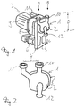
- a connector adapter 1 with a housing 2 is made Plastic shown.
- the cable ducts in the housing are not shown.
- the connection adapter 1 with its end face 3 ( Figure 2), the compatible System connections, on a three-way valve 4 appropriate.
- the three-way valve 4 points in this Embodiment a distribution box 5 and a switching unit 6 on.
- the three-way valve 4 is in turn with one conventional centrifugal pump 7 with hydraulic unit 8 and electric motor 9 hydraulically connected.
- the system connections whose openings are in planes that are parallel to the plane of rotation of the impeller arranged in the hydraulic unit 8 are compatible.
- connection adapter 1 Connection piece 10, 11 and 12, the openings of which in levels are perpendicular to the system connections.
- the openings of the connecting piece 10 and 11 lie in a first plane which is at a distance D from Level of the axially parallel connection piece 12 has.
- the distance D in this particular case is 180 mm.
- FIG. 2 shows an embodiment of a connection adapter 1 shown in Figure 1, in which the connecting piece 10 on the Axis of the connector 12 is while the connector 11 is laterally spaced by the distance E.
Landscapes
- Engineering & Computer Science (AREA)
- Physics & Mathematics (AREA)
- Thermal Sciences (AREA)
- Chemical & Material Sciences (AREA)
- Combustion & Propulsion (AREA)
- Mechanical Engineering (AREA)
- General Engineering & Computer Science (AREA)
- Structures Of Non-Positive Displacement Pumps (AREA)
- Quick-Acting Or Multi-Walled Pipe Joints (AREA)
Abstract
wobei die Öffnungen der kompatiblen Systemanschüsse in Ebenen liegen, die parallel zur Drehebene eines Laufrades einer Kreiselpumpe 7 sind,
und wobei die kompatiblen Systemanschüsse in einer Ebene parallel zur Drehebene des Laufrades liegen,
und mit Anschlußtutzen 10, 11 und 12, deren Öffnungen in Ebenen senkrecht zu den Systemanschüssen liegen, und die den Anschluß an herkömmliche Rohrleitungen insbesondere von Heizungsanlagen ermöglichen.
Description
- Fig. 1
- einen Anschlußadapter in Verbindung mit einer Pumpe und einem Ventil,
- Fig. 2
- einen Anschlußadapter.
Claims (15)
- Anschlußadapter (1), der ein Gehäuse (2) mit darin befindlichen Leitungkanälen aufweist, für ein System bei dem eine oder mehrere Kreiselpumpen (7) mit Komponenten wie Ein- oder Mehrwegeventilen (4) und/oder Verteilerstücken über kompatible Systemanschüsse hydraulisch verschaltbar sind,wobei die Öffnungen der kompatiblen Systemanschüsse in Ebenen liegen, die parallel zur Drehebene eines Laufrades einer Kreiselpumpe (7) sind,und wobei die kompatiblen Systemanschüsse in einer Ebene parallel zur Drehebene des Laufrades liegen,und mit Anschlußtutzen (10,11,12), deren Öffnungen in Ebenen senkrecht zu den Systemanschüssen liegen, und die den Anschluß an herkömmliche Rohrleitungen insbesondere von Heizungsanlagen ermöglichen.
- Anschlußadapter nach Anspruch 1,
gekennzeichnet durch drei Anschlußtutzen (10,11,12) wobei zwei Anschlußtutzen (10,11) achsparallel so angeordnet sind, daß ihre Öffnungen in einer ersten Ebene liegen und wobei ein dritter Anschlußtutzen (12) achsparallel so angeordnet ist, daß seine Öffnung in einer zweiten Ebene liegt, die zur ersten Ebene parallel ist. - Anschlußadapter nach Anspruch 2,
dadurch gekennzeichnet, daß einer der Anschlußtutzen (10) in der ersten Ebene auf der Achse des dritten Anschlußtutzen (12) liegt. - Anschlußadapter nach Anspruch 1,
gekennzeichnet durch vier Anschlußtutzen wobei zwei Anschlußtutzen achsparallel so angeordnet sind, daß ihre Öffnungen in einer ersten Ebene liegen und wobei zwei Anschlußtutzen achsparallel so angeordnet sind, daß ihre Öffnungen in einer zweiten Ebene liegen, die zur ersten Ebene parallel ist. - Anschlußadapter nach Anspruch 4,
dadurch gekennzeichnet, daß jeweils einer der Anschlußtutzen in der ersten Ebene in achsialer Ausrichtung zu einem der Anschlußtutzen in der zweiten Ebene liegen. - Anschlußadapter nach einem der vorherigen Ansprüche,
dadurch gekennzeichnet, daß die parallelen Ebenen der Anschlußstutzen einen Abstand (D) von 180 mm aufweisen. - Anschlußadapter nach einem der vorherigen Ansprüche,
dadurch gekennzeichnet, daß das Gehäuse (2) und die darin befindlichen Leitungkanälen einstückig aus aus Metall oder Kunststoff, insbesondere Polyamid, gefertigt sind. - Anschlußadapter nach einem der vorherigen Ansprüche,
dadurch gekennzeichnet, daß mindestens einer der Anschlußstutzen (10,11,12) durch ein im Gehäuse angeordnetes Absperrventil verschließbar ist. - Anschlußadapter nach einem der vorherigen Ansprüche,
dadurch gekennzeichnet, daß mindestens zwei Leitungkanäle über eine durch ein Ventil verschließbare Bypaßleitung verbunden sind. - Anschlußadapter nach einem der vorherigen Ansprüche,
dadurch gekennzeichnet, daß in einem Leitungkanal ein Überströmventil angeordnet ist. - Anschlußadapter nach einem der vorherigen Ansprüche,
dadurch gekennzeichnet, daß in einem Leitungkanal eine Einrichtung insbesondere eine Membran zum Ausgleichen von Druckspitzen integriert ist. - Anschlußadapter nach einem der vorherigen Ansprüche,
dadurch gekennzeichnet, daß in einem Leitungkanal eine Einrichtung zum Filtern des Pumpmediums integriert ist. - Anschlußadapter nach einem der vcrherigen Ansprüche,
dadurch gekennzeichnet, daß im Gehäuse Sensoren zur Messung der Systemparameter Wärmemenge, Volumenstrom, Systemdruck und/oder Temperatur angebracht sind.. - Anschlußadapter nach Anspruch 13,
dadurch gekennzeichnet, daß die Systemparameter auf Displays anzeigbar sind, die am Gehäuse angebracht sind. - Verwendung des Anschlußadapters nach einem der vorherigen Ansprüche in einer Hydraulikbaugruppe für eine kombinierte Heizwasser- und Sanitärwasseranlage.
Applications Claiming Priority (2)
| Application Number | Priority Date | Filing Date | Title |
|---|---|---|---|
| DE19711179 | 1997-03-18 | ||
| DE19711179A DE19711179A1 (de) | 1997-03-18 | 1997-03-18 | Anschlußadapter |
Publications (3)
| Publication Number | Publication Date |
|---|---|
| EP0866280A2 true EP0866280A2 (de) | 1998-09-23 |
| EP0866280A3 EP0866280A3 (de) | 2000-04-26 |
| EP0866280B1 EP0866280B1 (de) | 2004-09-01 |
Family
ID=7823736
Family Applications (1)
| Application Number | Title | Priority Date | Filing Date |
|---|---|---|---|
| EP98103869A Expired - Lifetime EP0866280B1 (de) | 1997-03-18 | 1998-03-05 | Anschlussadapter |
Country Status (2)
| Country | Link |
|---|---|
| EP (1) | EP0866280B1 (de) |
| DE (2) | DE19711179A1 (de) |
Cited By (3)
| Publication number | Priority date | Publication date | Assignee | Title |
|---|---|---|---|---|
| EP1217310A1 (de) * | 2000-12-22 | 2002-06-26 | Grundfos A/S | Kompaktaggregat |
| ITTO20110334A1 (it) * | 2011-04-13 | 2012-10-14 | Elbi Int Spa | Gruppo idraulico di pompaggio per una caldaia per un impianto di riscaldamento e di generazione di acqua calda sanitaria |
| US10012395B2 (en) | 2012-01-09 | 2018-07-03 | Grundfos Holding A/S | Heating unit |
Families Citing this family (1)
| Publication number | Priority date | Publication date | Assignee | Title |
|---|---|---|---|---|
| DE20103992U1 (de) | 2001-03-07 | 2001-05-31 | Grundfos A/S, Bjerringbro | Ventileinsatz für ein Dreiwege-Sitzventil zum Umschalten zwischen zwei Warmwasserkreisen einer Heizungsanlage mit einer Kreiselpumpe |
Family Cites Families (6)
| Publication number | Priority date | Publication date | Assignee | Title |
|---|---|---|---|---|
| NL6708548A (de) * | 1966-06-28 | 1967-12-29 | ||
| CH553335A (de) * | 1972-06-21 | 1975-01-15 | Hagenbucher Armin Hermann | Schlammwasserpumpaggregat. |
| DE3152861C2 (de) * | 1981-05-14 | 1983-12-01 | Robert Bosch Gmbh, 7000 Stuttgart | Dämpferelement |
| AT390667B (de) * | 1988-03-24 | 1990-06-11 | Vaillant Gmbh | Umlaufheizung |
| US4897023A (en) * | 1988-11-28 | 1990-01-30 | Milton Roy Company | Liquid pump assembly |
| DE8900912U1 (de) * | 1989-01-27 | 1989-06-22 | Laing, Karsten, 7148 Remseck | Beimischmodul |
-
1997
- 1997-03-18 DE DE19711179A patent/DE19711179A1/de not_active Withdrawn
-
1998
- 1998-03-05 EP EP98103869A patent/EP0866280B1/de not_active Expired - Lifetime
- 1998-03-05 DE DE59811880T patent/DE59811880D1/de not_active Expired - Fee Related
Cited By (5)
| Publication number | Priority date | Publication date | Assignee | Title |
|---|---|---|---|---|
| EP1217310A1 (de) * | 2000-12-22 | 2002-06-26 | Grundfos A/S | Kompaktaggregat |
| ITTO20110334A1 (it) * | 2011-04-13 | 2012-10-14 | Elbi Int Spa | Gruppo idraulico di pompaggio per una caldaia per un impianto di riscaldamento e di generazione di acqua calda sanitaria |
| WO2012140584A1 (en) * | 2011-04-13 | 2012-10-18 | Elbi International S.P.A. | Hydraulic unit |
| EP3453978A3 (de) * | 2011-04-13 | 2019-06-12 | ELBI International S.p.A. | Pumpeneinheit für einen kessel einer anlage zum heizen und zum erzeugen von warmem brauchwasser |
| US10012395B2 (en) | 2012-01-09 | 2018-07-03 | Grundfos Holding A/S | Heating unit |
Also Published As
| Publication number | Publication date |
|---|---|
| EP0866280A3 (de) | 2000-04-26 |
| EP0866280B1 (de) | 2004-09-01 |
| DE59811880D1 (de) | 2004-10-07 |
| DE19711179A1 (de) | 1998-09-24 |
Similar Documents
| Publication | Publication Date | Title |
|---|---|---|
| EP0092032B1 (de) | Vorrichtung zum Übergeben von wärme von einer Versorgungsleitung zu einem Abnehmer | |
| EP1130342B1 (de) | Baueinheit für eine Kompaktheizungsanlage | |
| WO2004088186A1 (de) | Einrichtung zur steuerung der strömung von flüssigen oder gasförmigen medien | |
| EP0866280B1 (de) | Anschlussadapter | |
| DE3241536C2 (de) | ||
| DE102006021800B3 (de) | Armaturenbausatz zum Be- oder Nachfüllen von Heizungssystemen | |
| EP0221464A2 (de) | Strangregulierventil | |
| EP3012553B1 (de) | Baueinheit für eine Heizungsanlage | |
| DE4113805C1 (en) | Subsequent fitting system for installed pipeline - has crosspiece with deflector baffle and interconnecting line for two crosspiece branches | |
| AT396267B (de) | Verteilergarnitur fuer brauchwasserinstallationen | |
| DE3736107C2 (de) | ||
| EP1666726B1 (de) | Baukastensystem für Fluidpumpenvorrichtungen | |
| DE3100564A1 (de) | Montage-anschlussstueck fuer filterstationen von versorgungsleitungen | |
| DE19632604A1 (de) | Befülleinrichtung für Hydraulikbaugruppe | |
| DE9105195U1 (de) | Nachrüstsystem für eine installierte Rohrleitung | |
| EP0255936A1 (de) | Anschlusszwischenstück zum Einbau in die Wasserleitung | |
| DE2929480A1 (de) | Armatur mit mehrfachfunktion | |
| DE19545446C2 (de) | Beidends mit einem Absperrorgan versehener Leitungsabschnitt mit einer um den Leitungabschnitt herumführenden absperrbaren Bypaß-Leitung | |
| DE8028344U1 (de) | Anschlusstueck fuer wasserleitungen | |
| DE2036230B2 (de) | Verrohrungsarmatur mit einem quader formigen Montagekopf | |
| EP2093516B1 (de) | Baueinheit für eine Kompaktheizungsanlage | |
| DE19711085A1 (de) | Drei- oder Vier-Wegeventil und Adapterstück | |
| DE3026463A1 (de) | Einrohr-anschlussstueck fuer waermemengenzaehler oder filteraufsatz mit koaxialem aufsetzstutzen | |
| CH695704A5 (de) | Armatur insbesondere zur Verwendung als Verteiler in einem Leitungssystem. | |
| EP0856690A2 (de) | Drei- oder Vier-Wegeventil und Adapterstück |
Legal Events
| Date | Code | Title | Description |
|---|---|---|---|
| PUAI | Public reference made under article 153(3) epc to a published international application that has entered the european phase |
Free format text: ORIGINAL CODE: 0009012 |
|
| AK | Designated contracting states |
Kind code of ref document: A2 Designated state(s): DE FR GB IT |
|
| AX | Request for extension of the european patent |
Free format text: AL;LT;LV;MK;RO;SI |
|
| PUAL | Search report despatched |
Free format text: ORIGINAL CODE: 0009013 |
|
| AK | Designated contracting states |
Kind code of ref document: A3 Designated state(s): AT BE CH DE DK ES FI FR GB GR IE IT LI LU MC NL PT |
|
| AX | Request for extension of the european patent |
Free format text: AL;LT;LV;MK;RO;SI |
|
| 17P | Request for examination filed |
Effective date: 20000405 |
|
| AKX | Designation fees paid |
Free format text: DE FR GB IT |
|
| 17Q | First examination report despatched |
Effective date: 20030310 |
|
| GRAP | Despatch of communication of intention to grant a patent |
Free format text: ORIGINAL CODE: EPIDOSNIGR1 |
|
| GRAS | Grant fee paid |
Free format text: ORIGINAL CODE: EPIDOSNIGR3 |
|
| RAP1 | Party data changed (applicant data changed or rights of an application transferred) |
Owner name: WILO AG |
|
| GRAA | (expected) grant |
Free format text: ORIGINAL CODE: 0009210 |
|
| AK | Designated contracting states |
Kind code of ref document: B1 Designated state(s): DE FR GB IT |
|
| REG | Reference to a national code |
Ref country code: GB Ref legal event code: FG4D Free format text: NOT ENGLISH |
|
| REF | Corresponds to: |
Ref document number: 59811880 Country of ref document: DE Date of ref document: 20041007 Kind code of ref document: P |
|
| GBT | Gb: translation of ep patent filed (gb section 77(6)(a)/1977) |
Effective date: 20040922 |
|
| ET | Fr: translation filed | ||
| PLBE | No opposition filed within time limit |
Free format text: ORIGINAL CODE: 0009261 |
|
| STAA | Information on the status of an ep patent application or granted ep patent |
Free format text: STATUS: NO OPPOSITION FILED WITHIN TIME LIMIT |
|
| 26N | No opposition filed |
Effective date: 20050602 |
|
| PGFP | Annual fee paid to national office [announced via postgrant information from national office to epo] |
Ref country code: GB Payment date: 20090304 Year of fee payment: 12 |
|
| PGFP | Annual fee paid to national office [announced via postgrant information from national office to epo] |
Ref country code: IT Payment date: 20090319 Year of fee payment: 12 Ref country code: DE Payment date: 20090226 Year of fee payment: 12 |
|
| PGFP | Annual fee paid to national office [announced via postgrant information from national office to epo] |
Ref country code: FR Payment date: 20090316 Year of fee payment: 12 |
|
| GBPC | Gb: european patent ceased through non-payment of renewal fee |
Effective date: 20100305 |
|
| REG | Reference to a national code |
Ref country code: FR Ref legal event code: ST Effective date: 20101130 |
|
| PG25 | Lapsed in a contracting state [announced via postgrant information from national office to epo] |
Ref country code: FR Free format text: LAPSE BECAUSE OF NON-PAYMENT OF DUE FEES Effective date: 20100331 |
|
| PG25 | Lapsed in a contracting state [announced via postgrant information from national office to epo] |
Ref country code: DE Free format text: LAPSE BECAUSE OF NON-PAYMENT OF DUE FEES Effective date: 20101001 |
|
| PG25 | Lapsed in a contracting state [announced via postgrant information from national office to epo] |
Ref country code: IT Free format text: LAPSE BECAUSE OF NON-PAYMENT OF DUE FEES Effective date: 20100305 Ref country code: GB Free format text: LAPSE BECAUSE OF NON-PAYMENT OF DUE FEES Effective date: 20100305 |