EP0866357A2 - Modulateur acousto-optique - Google Patents
Modulateur acousto-optique Download PDFInfo
- Publication number
- EP0866357A2 EP0866357A2 EP98103809A EP98103809A EP0866357A2 EP 0866357 A2 EP0866357 A2 EP 0866357A2 EP 98103809 A EP98103809 A EP 98103809A EP 98103809 A EP98103809 A EP 98103809A EP 0866357 A2 EP0866357 A2 EP 0866357A2
- Authority
- EP
- European Patent Office
- Prior art keywords
- acoustooptical
- medium
- optical signal
- modulator
- optical
- Prior art date
- Legal status (The legal status is an assumption and is not a legal conclusion. Google has not performed a legal analysis and makes no representation as to the accuracy of the status listed.)
- Withdrawn
Links
Images

Classifications
-
- G—PHYSICS
- G02—OPTICS
- G02F—OPTICAL DEVICES OR ARRANGEMENTS FOR THE CONTROL OF LIGHT BY MODIFICATION OF THE OPTICAL PROPERTIES OF THE MEDIA OF THE ELEMENTS INVOLVED THEREIN; NON-LINEAR OPTICS; FREQUENCY-CHANGING OF LIGHT; OPTICAL LOGIC ELEMENTS; OPTICAL ANALOGUE/DIGITAL CONVERTERS
- G02F1/00—Devices or arrangements for the control of the intensity, colour, phase, polarisation or direction of light arriving from an independent light source, e.g. switching, gating or modulating; Non-linear optics
- G02F1/01—Devices or arrangements for the control of the intensity, colour, phase, polarisation or direction of light arriving from an independent light source, e.g. switching, gating or modulating; Non-linear optics for the control of the intensity, phase, polarisation or colour
- G02F1/11—Devices or arrangements for the control of the intensity, colour, phase, polarisation or direction of light arriving from an independent light source, e.g. switching, gating or modulating; Non-linear optics for the control of the intensity, phase, polarisation or colour based on acousto-optical elements, e.g. using variable diffraction by sound or like mechanical waves
-
- G—PHYSICS
- G02—OPTICS
- G02F—OPTICAL DEVICES OR ARRANGEMENTS FOR THE CONTROL OF LIGHT BY MODIFICATION OF THE OPTICAL PROPERTIES OF THE MEDIA OF THE ELEMENTS INVOLVED THEREIN; NON-LINEAR OPTICS; FREQUENCY-CHANGING OF LIGHT; OPTICAL LOGIC ELEMENTS; OPTICAL ANALOGUE/DIGITAL CONVERTERS
- G02F1/00—Devices or arrangements for the control of the intensity, colour, phase, polarisation or direction of light arriving from an independent light source, e.g. switching, gating or modulating; Non-linear optics
- G02F1/01—Devices or arrangements for the control of the intensity, colour, phase, polarisation or direction of light arriving from an independent light source, e.g. switching, gating or modulating; Non-linear optics for the control of the intensity, phase, polarisation or colour
- G02F1/03—Devices or arrangements for the control of the intensity, colour, phase, polarisation or direction of light arriving from an independent light source, e.g. switching, gating or modulating; Non-linear optics for the control of the intensity, phase, polarisation or colour based on ceramics or electro-optical crystals, e.g. exhibiting Pockels effect or Kerr effect
- G02F1/0305—Constructional arrangements
- G02F1/0322—Arrangements comprising two or more independently controlled crystals
Definitions
- the present invention relates to an acoustooptical modulator, such as those used in optical measuring devices.
- An acoustooptical modulator adds a modulation signal to a piezoelectric element, and causes periodic oscillation in the refractive index within an optical medium by ultrasonic waves produced therein, modulating the beam.
- Fig. 4 is a block diagram showing an example of the arrangement of the conventional technology for an acoustooptical modulator.
- the optical signal propagated by an optical fiber 51 is focused by a lens 52 and is incident on the acoustooptical modulator 58.
- the ultrasonic band frequency signal produced by the oscillator 53 is incident on the piezoelectric vibrator 54 installed on the acoustooptical medium 58, and the ultrasonic waves produced by this piezoelectric vibrator cause periodic oscillation of the refractive index of the acoustooptical medium 58.
- the optical signal incident from the optical fiber 51 is separated into the transmitted beam and the primary diffracted beam due to a diffraction grating being formed in the acoustooptical medium 58.
- the optical signal output from this acoustooptical modulator transits a prism 55, and after being focused by a lens 56, is emitted by the optical fiber 57.
- the arrangement shown in Fig. 4 realizes a mechanism for switching on and off an optical signal transiting between the optical fiber 51 and the optical fiber 57, and is widely used as, for example, a measuring device.
- Fig. 5 is a chart showing the wavelength-dependent characteristics of the loss of the acoustooptical modulator shown in Fig. 4.
- ripple characteristics can be observed in the wavelength loss characteristics. This is believed to be due to polarization mode scattering produced by birefringence characteristics of the acoustooptical medium.
- the present invention comprising a first acoustooptical medium upon which an optical signal from a first optical fiber is incident, and through which the optical signal transits; a vibrator mounted on a surface parallel to the optic axis of the optical signal in the first acoustooptical medium; and an oscillator that supplies a modulated signal to the vibrator; and in an acoustooptical modulator that emits the optical signal though a second optical fiber, a second acoustooptical medium mounted along the optic axis between the first optical fiber and the second optical fiber, which has an identical material and identical optical path length as the first acoustooptical modulator, and is disposed rotated 90o with respect to the direction of the crystal axis of the first acoustooptical medium.
- the first acoustooptical medium having a vibrator for providing ultrasonic vibration modulates the incident optical signal, and transmits the incident optical signal to the second acoustooptical medium which is rotated 90o with respect to the direction of the crystal axis of the first acoustooptical medium. Because the polarization mode scattering due to the birefringence of each acoustooptical medium is eliminated, it is possible to realize an acoustooptical modulator with no ripple in the wavelength loss characteristics.
- first and second acoustooptical media which are rectangular parallelepipeds having an incident surface orthogonal to the optic axis of the optical signal.
- the present invention may be provided with a prism that alters the direction of the progress of the optical signal between the second acoustooptical medium and the second optical fiber.
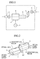
- Fig. 1 shows a structural diagram of the acoustooptical modulator according to the first embodiment of the present invention.
- Fig. 2 is a cross-section diagram showing the relationship between the positions of the acoustooptical medium 8 and the acoustooptical medium 9 in the same embodiment.
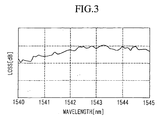
- Fig. 3 is a diagram showing the wavelength loss characteristics of the acoustooptical modulator in the same embodiment.
- Fig. 4 is a diagram showing the wavelength loss characteristics of the acoustooptical modulator shown in Fig. 4.
- Fig. 5 is a diagram showing the wavelength loss characteristics of the acoustooptical modulator shown in Fig. 4.
- Fig. 1 is a structural diagram showing the arrangement of the acoustooptical modulator of an embodiment of the present invention.
- reference numeral 1 is an optical fiber supplying an optical signal to the acoustooptical modulator of the present invention.
- Reference numeral 2 is a lens that focuses the supplied optical signal.
- Reference numeral 8 is acoustooptical medium, and the optical signal focused by the lens 2 is incident thereon.
- a piezoelectric vibrator is disposed on this acoustooptical medium 8.
- Reference numeral 3 is an oscillator producing a modulated signal supplied to the piezoelectric vibrator 4 disposed on the acoustooptical medium 8.
- FIG. 2 is a cross-sectional diagram showing the relationship of the positions of the acoustooptical medium 8 and the acoustooptical medium 9.
- the acoustooptical medium 8 and the acoustooptical medium 9 in the present embodiment are of identical material and both have the form of a rectangular parallelepiped.
- the lengths of the edges a, b, and c of acoustooptical medium 8 and acoustooptical medium 9 are identical.
- edges a and b of acoustooptical medium 8 and acoustooptical medium 9 are mutually rotated 90o with respect to the center of the optic axis. That is, with respect to acoustooptical medium 8, acoustooptical medium 9 is rotated 90o on the direction of the crystal axis.
- a cyclic modulation of the refractive index is produced inside the acoustooptical medium 8 by ultrasonic waves when a modulated signal is supplied by piezoelectric vibrator 4 from oscillator 3, and a diffraction grating is formed.
- the optical signal supplied to the acoustooptical modulator of the present embodiment by the optical fiber is focused by the lens 2 incident on the acoustooptical medium 8.
- the optical signal which has entered acoustooptical medium 8 is diffracted by the diffraction grating formed therein, and separated into the transiting beam and the primary diffraction beam.
- the optical signal which has transited the acoustooptical medium 8 is subject to polarization mode scattering because of the birefringence of the acoustooptical medium 9.
- the optical signal emitted from the acoustooptical medium 8 is next incident on the acoustico-optic medium 9.
- the acoustooptical medium 8 and the acoustooptical medium 9 are mutually rotated 90o with respect to their optic. Due to this, the polarization mode scattering produced in transiting acoustooptical medium 8 is cancelled in transiting acoustooptical medium 9.
- the optical signal that has transited acoustooptical medium 9 passes through prism 5, is focused by lens 6, and subsequently is emitted from the acoustooptical modulator from the emitting end of optical fiber 7.
- Fig. 3 is a diagram showing the wavelength loss characteristics of the acoustooptical modulator according to the present embodiment. In such an embodiment, even when there is a change in the wavelength of the optical signal, a beam without ripple characteristics is obtained.
- acoustooptical media 8 and 9 were rectangular parallelepipeds, but additionally, any form having an incident surface nearly orthogonal to the optic axis of the transiting optical signal, for example, a cylindrical column, is suitable.
- the present invention can be structured so that if the direction of the crystal axis of the acoustooptical medium 9 is rotated 90o with respect to the acoustooptical medium 8, the acoustooptical medium 9 can be interposed between acoustooptical medium 8 and lens 2 on the optic axis.
- either the transiting beam or the primary diffracted beam of the optical signal that is emitted from the acoustooptical medium 8 can be used in the present invention.
Landscapes
- Physics & Mathematics (AREA)
- Nonlinear Science (AREA)
- General Physics & Mathematics (AREA)
- Optics & Photonics (AREA)
- Optical Modulation, Optical Deflection, Nonlinear Optics, Optical Demodulation, Optical Logic Elements (AREA)
- Liquid Crystal (AREA)
Applications Claiming Priority (3)
| Application Number | Priority Date | Filing Date | Title |
|---|---|---|---|
| JP4948497 | 1997-03-04 | ||
| JP9049484A JPH10246875A (ja) | 1997-03-04 | 1997-03-04 | 音響光学変調器 |
| JP49484/97 | 1997-03-04 |
Publications (2)
| Publication Number | Publication Date |
|---|---|
| EP0866357A2 true EP0866357A2 (fr) | 1998-09-23 |
| EP0866357A3 EP0866357A3 (fr) | 1999-09-08 |
Family
ID=12832443
Family Applications (1)
| Application Number | Title | Priority Date | Filing Date |
|---|---|---|---|
| EP98103809A Withdrawn EP0866357A3 (fr) | 1997-03-04 | 1998-03-04 | Modulateur acousto-optique |
Country Status (3)
| Country | Link |
|---|---|
| US (1) | US6008930A (fr) |
| EP (1) | EP0866357A3 (fr) |
| JP (1) | JPH10246875A (fr) |
Cited By (2)
| Publication number | Priority date | Publication date | Assignee | Title |
|---|---|---|---|---|
| RU2161827C2 (ru) * | 1999-01-10 | 2001-01-10 | Институт автоматики и электрометрии СО РАН | Способ многослойной оптической записи и воспроизведения двоичной информации |
| DE10058999A1 (de) * | 2000-11-28 | 2002-05-29 | Heidelberger Druckmasch Ag | Verfahren und Vorrichtung zur Modulation von unpolarisiertem Licht |
Families Citing this family (3)
| Publication number | Priority date | Publication date | Assignee | Title |
|---|---|---|---|---|
| US6754000B2 (en) * | 2000-10-04 | 2004-06-22 | Leica Microsystems Heidelberg Gmbh | Optical arrangement, and method for the deflection of light beams |
| CN100374951C (zh) * | 2005-03-25 | 2008-03-12 | 清华大学 | 用于双包层光纤激光器的声光调q方法及其装置 |
| CN109507117B (zh) * | 2018-11-12 | 2020-04-03 | 中国科学技术大学 | 一种基于光声束整形的微纳成像检测实验装置 |
Family Cites Families (6)
| Publication number | Priority date | Publication date | Assignee | Title |
|---|---|---|---|---|
| CH577691A5 (fr) * | 1974-10-23 | 1976-07-15 | Bbc Brown Boveri & Cie | |
| US4330178A (en) * | 1979-10-29 | 1982-05-18 | Mcnaney Joseph T | Illuminated subject matter image dissecting and elemental light output alignment control means |
| US4440472A (en) * | 1981-04-24 | 1984-04-03 | The United States Of America As Represented By The Director Of National Security Agency | Space integrating ambiguity processor |
| JPS60205430A (ja) * | 1984-03-30 | 1985-10-17 | Fuji Photo Film Co Ltd | 光ビ−ム走査装置 |
| JPS63307434A (ja) * | 1987-06-10 | 1988-12-15 | Nec Corp | 音響光学スイッチ |
| JPH01216316A (ja) * | 1988-02-25 | 1989-08-30 | Asahi Glass Co Ltd | 音響光学qスイッチ素子 |
-
1997
- 1997-03-04 JP JP9049484A patent/JPH10246875A/ja active Pending
-
1998
- 1998-03-04 US US09/034,824 patent/US6008930A/en not_active Expired - Fee Related
- 1998-03-04 EP EP98103809A patent/EP0866357A3/fr not_active Withdrawn
Cited By (4)
| Publication number | Priority date | Publication date | Assignee | Title |
|---|---|---|---|---|
| RU2161827C2 (ru) * | 1999-01-10 | 2001-01-10 | Институт автоматики и электрометрии СО РАН | Способ многослойной оптической записи и воспроизведения двоичной информации |
| DE10058999A1 (de) * | 2000-11-28 | 2002-05-29 | Heidelberger Druckmasch Ag | Verfahren und Vorrichtung zur Modulation von unpolarisiertem Licht |
| EP1211553A3 (fr) * | 2000-11-28 | 2003-08-27 | Heidelberger Druckmaschinen Aktiengesellschaft | Procédé et dispositif pour la modulation de lumière non polarisée |
| US6618183B2 (en) | 2000-11-28 | 2003-09-09 | Heidelberger Druckmaschinen Aktiengesellschaft | Method and apparatus for modulating unpolarized light |
Also Published As
| Publication number | Publication date |
|---|---|
| JPH10246875A (ja) | 1998-09-14 |
| EP0866357A3 (fr) | 1999-09-08 |
| US6008930A (en) | 1999-12-28 |
Similar Documents
| Publication | Publication Date | Title |
|---|---|---|
| JPH04297081A (ja) | 光学掃引発振器 | |
| US6775307B2 (en) | Light wavelength conversion module | |
| US6944194B1 (en) | Light scanning and recording apparatus | |
| US4788514A (en) | Optical modulation arrangement | |
| JP3383697B2 (ja) | 青色、緑色および赤色出力波長を生成するモノリシック半導体レーザ | |
| US6008930A (en) | Acoustooptical modulator | |
| JP2003295142A (ja) | 光源内蔵型光変調器モジュール | |
| JPH0451006B2 (fr) | ||
| JPH05249526A (ja) | 光学発振器 | |
| KR910009133B1 (ko) | 레이저광을 이용하는 정보기기 | |
| JPH08510571A (ja) | 電磁放射の周波数を上昇させる装置 | |
| US4606031A (en) | Device for frequency modulation of a laser output spectrum | |
| JPH1172763A (ja) | 音響光学変調器 | |
| JPH04146681A (ja) | 半導体レーザ装置 | |
| JP2937418B2 (ja) | 半導体レーザ装置 | |
| US3507553A (en) | Ultrasonic digital light deflector | |
| JP2000111854A (ja) | 音響光学変調装置 | |
| JPS60144715A (ja) | 光周波数変調器 | |
| JPS622293B2 (fr) | ||
| SU1127515A1 (ru) | Субмиллиметровый лазер с внутренней амплитудной модул цией | |
| JPS6025916B2 (ja) | 固体レ−ザ−装置 | |
| JPS6159573B2 (fr) | ||
| JPS63266430A (ja) | 光高調波発生装置 | |
| JPS62229890A (ja) | 可変波長半導体光源 | |
| JPH0511297A (ja) | 光波長変換素子 |
Legal Events
| Date | Code | Title | Description |
|---|---|---|---|
| PUAI | Public reference made under article 153(3) epc to a published international application that has entered the european phase |
Free format text: ORIGINAL CODE: 0009012 |
|
| AK | Designated contracting states |
Kind code of ref document: A2 Designated state(s): DE FR GB IT |
|
| AX | Request for extension of the european patent |
Free format text: AL;LT;LV;MK;RO;SI |
|
| PUAL | Search report despatched |
Free format text: ORIGINAL CODE: 0009013 |
|
| AK | Designated contracting states |
Kind code of ref document: A3 Designated state(s): AT BE CH DE DK ES FI FR GB GR IE IT LI LU MC NL PT SE |
|
| AX | Request for extension of the european patent |
Free format text: AL;LT;LV;MK;RO;SI |
|
| 17P | Request for examination filed |
Effective date: 20000221 |
|
| AKX | Designation fees paid |
Free format text: DE FR GB IT |
|
| 17Q | First examination report despatched |
Effective date: 20040203 |
|
| RAP1 | Party data changed (applicant data changed or rights of an application transferred) |
Owner name: YOKOGAWA ELECTRIC CORPORATION |
|
| STAA | Information on the status of an ep patent application or granted ep patent |
Free format text: STATUS: THE APPLICATION IS DEEMED TO BE WITHDRAWN |
|
| 18D | Application deemed to be withdrawn |
Effective date: 20060916 |