EP0866370A1 - Rolle zur Verwendung in Nassbehandlungsgerät - Google Patents
Rolle zur Verwendung in NassbehandlungsgerätInfo
- Publication number
- EP0866370A1 EP0866370A1 EP97200853A EP97200853A EP0866370A1 EP 0866370 A1 EP0866370 A1 EP 0866370A1 EP 97200853 A EP97200853 A EP 97200853A EP 97200853 A EP97200853 A EP 97200853A EP 0866370 A1 EP0866370 A1 EP 0866370A1
- Authority
- EP
- European Patent Office
- Prior art keywords
- roller
- sheet material
- region
- rollers
- core
- Prior art date
- Legal status (The legal status is an assumption and is not a legal conclusion. Google has not performed a legal analysis and makes no representation as to the accuracy of the status listed.)
- Granted
Links
- 239000000463 material Substances 0.000 claims abstract description 75
- 230000007423 decrease Effects 0.000 claims abstract description 5
- 239000007788 liquid Substances 0.000 description 21
- 238000007789 sealing Methods 0.000 description 13
- 239000013536 elastomeric material Substances 0.000 description 12
- 238000010276 construction Methods 0.000 description 7
- 239000004411 aluminium Substances 0.000 description 4
- 229910052782 aluminium Inorganic materials 0.000 description 4
- XAGFODPZIPBFFR-UHFFFAOYSA-N aluminium Chemical compound [Al] XAGFODPZIPBFFR-UHFFFAOYSA-N 0.000 description 4
- 230000008901 benefit Effects 0.000 description 4
- 230000000694 effects Effects 0.000 description 4
- 229920001343 polytetrafluoroethylene Polymers 0.000 description 4
- 239000004810 polytetrafluoroethylene Substances 0.000 description 4
- 229940058401 polytetrafluoroethylene Drugs 0.000 description 4
- 239000004814 polyurethane Substances 0.000 description 3
- 229920002635 polyurethane Polymers 0.000 description 3
- 239000010935 stainless steel Substances 0.000 description 3
- 229910001220 stainless steel Inorganic materials 0.000 description 3
- 229920002943 EPDM rubber Polymers 0.000 description 2
- 229920000459 Nitrile rubber Polymers 0.000 description 2
- 239000004743 Polypropylene Substances 0.000 description 2
- 239000000853 adhesive Substances 0.000 description 2
- 230000001070 adhesive effect Effects 0.000 description 2
- 229920005549 butyl rubber Polymers 0.000 description 2
- 238000000576 coating method Methods 0.000 description 2
- 239000002131 composite material Substances 0.000 description 2
- 150000001993 dienes Chemical class 0.000 description 2
- 238000006073 displacement reaction Methods 0.000 description 2
- 238000001035 drying Methods 0.000 description 2
- HQQADJVZYDDRJT-UHFFFAOYSA-N ethene;prop-1-ene Chemical group C=C.CC=C HQQADJVZYDDRJT-UHFFFAOYSA-N 0.000 description 2
- 238000000034 method Methods 0.000 description 2
- -1 polypropylene Polymers 0.000 description 2
- 229920001155 polypropylene Polymers 0.000 description 2
- 229920003031 santoprene Polymers 0.000 description 2
- 229920002379 silicone rubber Polymers 0.000 description 2
- 239000004945 silicone rubber Substances 0.000 description 2
- 239000000126 substance Substances 0.000 description 2
- 229920001897 terpolymer Polymers 0.000 description 2
- 229920002725 thermoplastic elastomer Polymers 0.000 description 2
- 238000004073 vulcanization Methods 0.000 description 2
- 241001479434 Agfa Species 0.000 description 1
- OKTJSMMVPCPJKN-UHFFFAOYSA-N Carbon Chemical compound [C] OKTJSMMVPCPJKN-UHFFFAOYSA-N 0.000 description 1
- NINIDFKCEFEMDL-UHFFFAOYSA-N Sulfur Chemical compound [S] NINIDFKCEFEMDL-UHFFFAOYSA-N 0.000 description 1
- 239000005864 Sulphur Substances 0.000 description 1
- RTAQQCXQSZGOHL-UHFFFAOYSA-N Titanium Chemical compound [Ti] RTAQQCXQSZGOHL-UHFFFAOYSA-N 0.000 description 1
- 239000011324 bead Substances 0.000 description 1
- 229910052799 carbon Inorganic materials 0.000 description 1
- 238000003763 carbonization Methods 0.000 description 1
- 239000011248 coating agent Substances 0.000 description 1
- 230000006835 compression Effects 0.000 description 1
- 238000007906 compression Methods 0.000 description 1
- 238000011109 contamination Methods 0.000 description 1
- 238000001816 cooling Methods 0.000 description 1
- 229920001971 elastomer Polymers 0.000 description 1
- 239000000806 elastomer Substances 0.000 description 1
- 238000001704 evaporation Methods 0.000 description 1
- 230000008020 evaporation Effects 0.000 description 1
- 239000011521 glass Substances 0.000 description 1
- 239000003365 glass fiber Substances 0.000 description 1
- 238000003754 machining Methods 0.000 description 1
- 230000009347 mechanical transmission Effects 0.000 description 1
- 229910052751 metal Inorganic materials 0.000 description 1
- 239000002184 metal Substances 0.000 description 1
- 239000000203 mixture Substances 0.000 description 1
- 229910021652 non-ferrous alloy Inorganic materials 0.000 description 1
- 230000003647 oxidation Effects 0.000 description 1
- 238000007254 oxidation reaction Methods 0.000 description 1
- 239000002245 particle Substances 0.000 description 1
- 150000002978 peroxides Chemical class 0.000 description 1
- 239000004033 plastic Substances 0.000 description 1
- 229920003023 plastic Polymers 0.000 description 1
- 229920000728 polyester Polymers 0.000 description 1
- 238000007639 printing Methods 0.000 description 1
- 230000002250 progressing effect Effects 0.000 description 1
- 230000000717 retained effect Effects 0.000 description 1
- 230000035945 sensitivity Effects 0.000 description 1
- 238000000926 separation method Methods 0.000 description 1
- 239000013464 silicone adhesive Substances 0.000 description 1
- 230000001360 synchronised effect Effects 0.000 description 1
- 239000010936 titanium Substances 0.000 description 1
- 229910052719 titanium Inorganic materials 0.000 description 1
Images

Classifications
-
- G—PHYSICS
- G03—PHOTOGRAPHY; CINEMATOGRAPHY; ANALOGOUS TECHNIQUES USING WAVES OTHER THAN OPTICAL WAVES; ELECTROGRAPHY; HOLOGRAPHY
- G03D—APPARATUS FOR PROCESSING EXPOSED PHOTOGRAPHIC MATERIALS; ACCESSORIES THEREFOR
- G03D3/00—Liquid processing apparatus involving immersion; Washing apparatus involving immersion
- G03D3/08—Liquid processing apparatus involving immersion; Washing apparatus involving immersion having progressive mechanical movement of exposed material
- G03D3/13—Liquid processing apparatus involving immersion; Washing apparatus involving immersion having progressive mechanical movement of exposed material for long films or prints in the shape of strips, e.g. fed by roller assembly
- G03D3/132—Liquid processing apparatus involving immersion; Washing apparatus involving immersion having progressive mechanical movement of exposed material for long films or prints in the shape of strips, e.g. fed by roller assembly fed by roller assembly
Definitions
- This invention relates to the construction of a roller suitable for use in an apparatus for the wet processing of photographic sheet material, such as X-ray film, pre-sensitised plates, graphic art film and paper, and offset plates.
- photographic sheet material such as X-ray film, pre-sensitised plates, graphic art film and paper, and offset plates.
- a processing apparatus for photographic sheet material comprises several vessels each of which contains a treatment liquid, such as a developer, a fixer and a rinse liquid.
- a treatment liquid such as a developer, a fixer and a rinse liquid.
- sheet material includes not only photographic material in the form of cut sheets, but also in the form of a web unwound from a roll.
- transport means such as one or more pairs of drive rollers, and thereafter optionally to a drying unit.
- the time spent by the sheet material in each vessel is determined by the transport speed and the dimensions of the vessel in the sheet feed path direction.
- the sheet material is transported along a generally horizontal feed path, the sheet material passing from one vessel to another usually via a circuitous feed path passing under the surface of each treatment liquid and over dividing walls between the vessels.
- the apparatus comprises a housing with pairs of processing rollers carried on roller shafts supported within the housing.
- the processing rollers are positioned substantially parallel and in line contact with each other.
- Means are provided for feeding photographic sheet material between the rollers.
- the roller shafts are biased towards each other to exert a pressure on the photographic sheet material as it passes between the rollers.
- Processing machines having a substantially vertical orientation have also been proposed, in which a plurality of vessels are mounted one above the other, each vessel having an opening at the top acting as a sheet material inlet and an opening at the bottom acting as a sheet material outlet or vice versa.
- substantially vertical is intended to mean that the sheet material moves along a path from the inlet to the outlet which is either exactly vertical, or which has a vertical component greater than any horizontal component.
- the sheet transport path in a vertically oriented apparatus may be substantially straight, in contrast to the circuitous feed path which is usual in a horizontally oriented apparatus.
- the material sensitivity to scratches becomes independent of the stiffness and thickness of the material.
- rollers are used in pairs, biased towards each other, between which the sheet material passes to act as a seal between treatment vessels of the processing apparatus, that is to remove excess treatment liquid from the sheet as it passes from one treatment vessel to the next. This reduces carry-over of treatment liquid and thereby reduces contamination and wastage. A good removal of processing liquid is also required to reduce the drying time of the sheet material after the last process bath, and hence to reduce the energy use.
- rollers also act as drive rollers, serving to advance the sheet material through the apparatus.
- the resilience of the rollers is important.
- rollers comprise a rigid core having a layer of, for example, elastomeric material positioned over the core. If the elastomeric material is too hard, the squeegeeing properties beyond the edges of the sheet material may not be optimum, resulting in an unacceptable level of carry-over. On the other hand, if the elastomeric material is too soft it will often contain oily materials which are liable to leach out of the elastomer and contaminate the sheet material, while the elastomeric material becomes progressively degraded.
- Typical rollers have a core provided with a covering of elastomeric material. As the sheet material leaves a given liquid treatment vessel it is necessary to remove any liquid carried on the sheet material as efficiently as possible, to prevent carry-over of liquid into a next treatment vessel and to reduce edge effects which arise from non-homogeneous chemistry on the sheet material after squeegeeing. This applies whether the apparatus is of a horizontal or vertical configuration. To do this job properly, the rollers must exert a sufficient and homogeneous pressure over the whole width of the sheet material. Also, to reduce edge effects, it is desirable that the opposite roller surfaces are in contact with each other beyond the edges of the sheet material.
- rollers used in conventional processing apparatus for example have a length of 400 mm or more and a diameter of from 24 to 60 mm.
- the sheet material typically has a width of from a few millimetres up to 2 m and a thickness of 0.05 mm to 0.5 mm.
- the elastomeric covering comprises an outer exposed region and an intermediate region positioned between the outer region and the core, and the intermediate and outer regions are shaped in a specified manner.
- a roller comprising a core having an elastomeric covering, characterised in that the elastomeric covering comprises an exposed outer region and an intermediate region positioned between the outer region and the core, the outer region having a thickness which decreases towards each end of the roller and the intermediate region having a thickness which increases towards each end of the roller.
- the intermediate region and the outer region are preferably constituted by distinguishable intermediate and outer layers, the outer region being formed of a material having a Shore-A hardness higher than that of the intermediate region.
- the difference between the Shore-A hardness of the intermediate layer and the outer layer being at preferably at least 5.
- the intermediate and outer regions are continuous, the Shore-a hardness varying through the thickness of the covering, being higher towards the outside of the roller.
- the roller comprises a rigid core, the intermediate region being positioned immediately over the core, i.e. directly in contact with the core and with the outer region.
- the total thickness of the outer and intermediate regions may be constant along the length of the roller.
- the outer diameter of the outer region varies along the length of the roller, in particular the outer diameter of the outer region decreases towards each end of the roller.
- the outer diameter of the roller at its centre may be up to 10%, but preferably not more than 2%, higher than at its ends.
- the change in roller surface velocity ( ⁇ v) across the width of the nip will also approach zero, leading to a condition where wrinkling of the sheet material is reduced.
- ⁇ v should be higher towards the ends of the roller, to achieve a sheet centring effect.
- the core may be formed of a material selected from stainless steel, non-ferrous alloys, titanium, aluminium or a composite thereof.
- the core will usually be rigid.
- the core will be formed of a material having uniform properties, in particular its E mod , along its length.
- the outer region may be constituted by a distinguishable outer layer having a minimum thickness of, for example, at least 0.2 mm, which may be from 1% to 10% of the overall roller diameter.
- the outer region may be formed of an elastomeric material selected from ethylene/propylene/diene terpolymers (EPDM), silicone rubber, polyurethane, thermoplastic rubber such as Santoprene (Trade Mark for polypropylene/EPDM rubber), styrene-butyl rubber and nitrile-butyl rubber and, particularly for the outer region, and such materials doped with a surface modifying material selected from PTFE (poly tetra fluoro ethylene) particles, carbon fibres, glass fibres, glass beads and mixtures thereof.
- the Shore-A hardness of the outer region may be more than 25, such as from 40 to 90.
- the intermediate region may be constituted by a distinguishable outer layer having a minimum thickness of, for example, at least 1.0 mm, which may be from 5% to 35% of the overall roller diameter.
- the intermediate region may be formed of an elastomeric material selected from ethylene/propylene/diene terpolymers (EPDM), silicone rubber, polyurethane, thermoplastic rubber such as Santoprene (Trade Mark for polypropylene/EPDM rubber), styrene-butyl rubber and nitrile-butyl rubber.
- EPDM ethylene/propylene/diene terpolymers
- silicone rubber silicone rubber
- polyurethane polyurethane
- thermoplastic rubber such as Santoprene (Trade Mark for polypropylene/EPDM rubber)
- styrene-butyl rubber styrene-butyl rubber and nitrile-butyl rubber.
- the Shore-A hardness of the intermediate region may be more than 50, such as from 15 to 45.
- the invention also provides an apparatus for the wet processing of sheet material, the apparatus including means defining a sheet material path through the apparatus and at least one pair of rollers biased into contact with each other to form a nip through which the sheet material path extends, at least one roller of the pair being as defined above.
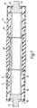
- a roller 12 comprises a stainless steel rigid core 56, an inner or intermediate layer of elastomeric material 58 positioned over the core, and an outer layer of elastomeric material 60 positioned over the intermediate layer. No other layers are present, so that the intermediate layer 58 is directly in contact with the core and with the outer layer 60.
- the roller covering has a length of 800 mm.
- the intermediate layer 58 has a variable thickness T 1 which varies along its length, from 6.50 mm at each end of the roller to 3.66 mm at the centre of the roller.
- the intermediate layer is formed of EPDM having a Shore-A hardness of 25 ⁇ 5.
- the outer layer 60 is also formed of EPDM, but in this case the Shore-A hardness is 50 ⁇ 5.
- the outer layer has a variable thickness T 2 which varies from 0.92 mm at each end of the roller to 3.84 mm at the centre of the roller.
- the roller core has a constant diameter of 25 mm.
- the roller therefore has a slightly convex outer diameter varying from 39.84 mm at each end to 40.00 mm at its centre.
- the thicknesses of the intermediate and outer layers, and the total elastomeric covering thickness (T 1 + T 2 ), as a function of the distance l along the roller from one end, are set out in the following table (all dimensions in mm).
- distance l intermediate thickness T 1 outer thickness T 2 total thickness T 1 + T 2 0 6.50 0.92 7.42 44 5.76 1.68 7.44 133 5.02 2.44 7.46 222 4.20 3.28 7.48 311 3.77 3.73 7.50 400 3.66 3.84 7.50 489 3.77 3.73 7.50 578 4.20 3.28 7.48 667 5.02 2.44 7.46 756 5.76 1.68 7.44 800 6.50 0.92 7.42
- the intermediate layer 58 is formed over the rigid core by coating an adhesive primer on the core and then applying non-vulcanised EPDM thereto. A plastic tape is then tightly applied over the EPDM to squeeze out any excess air.
- the assembly is placed in an autoclave at a pressure of 6 to 7 bar and at a temperature of 160 to 180°C for 1 to 2 hours in the presence of sulphur or a peroxide, to ensure vulcanisation.
- the intermediate layer 58 is ground to the desired profile.
- the outer layer 60 is formed by a similar process, followed by machining to ensure the desired profile.
- Figure 1 illustrates two possible embodiments of the invention.
- a separate portion 64 of the outer layer extends over the end face of the inner layer 58.
- This construction is particularly suitable when the outer layer is formed of EPDM, the end part 64 including PTFE as a friction reducing component to reduce the friction between the roller and the sealing surface of the apparatus.
- the portion 64 is so shaped as to provide a space 65 into which the elastomeric material of the covering may be deformed as a result of a sealing force between the roller and a sealing surface of the apparatus.
- the outer layer is thus formed in two parts, namely a part 60 which extends along the outer surface of the roller and another part 64 which extends over the end face of the inner layer 58.
- the two parts of the outer layer may be formed by separate vulcanisation steps.
- the outer region 60 itself extends over the end face of the inner layer 58. This construction is particularly suitable when the outer layer of elastomeric material is formed of polyurethane.
- shafts 16, 18 are suitably welded to the end of the core 56, or are integral therewith.
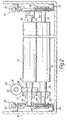
- the processing apparatus is mounted within a generally rectangular housing 10 which may include a rectangular metal mainframe (not shown in Figure 2 for the sake of clarity) for supporting the various sections of the apparatus.
- the apparatus includes a number of treatment vessels, sheet material to be processed being passed from one vessel to the next by squeegee roller pairs, which also serve as drive rollers.
- One such roller pair is shown in Figure 2, namely an upper squeegee roller 12 and a lower squeegee roller 14.
- the upper roller 12 is constructed as shown in Figure 1.
- the lower roller 14 is similarly constructed.
- the rollers 12 and 14 are positioned substantially parallel and in line contact with each other.
- the upper roller 12 is fixed on respective shafts 16 and 18 for rotation and the lower roller 14 is fixed on respective shafts 20 and 22 for rotation.
- the roller shafts 16, 18, 20, 22 are mounted at each end in bearings held in respective sub-frames 24.
- a drive device 26 for the rollers comprises a mechanical transmission for driving said processing roller 12 and a set of cooperating gears located at one end and at the same side of both roller shafts 16, 20.
- the upper processing roller 12 is driven at one end thereof through a worm-screw 34 and a worm-wheel 36 by a drive shaft 32, which links all upper rollers in the apparatus.
- the lower processing roller 14 is driven by a helical gear 38 which meshes with another helical gear 40.
- the drive shaft 32 is driven preferably by an electric motor with an encoding disc system (not shown) in order to control the speed and the progressing horizontal position of the sheet material.
- the coordinates of the upper processing roller 12 are defined by the end bearings 42 and 44.
- the lower roller 14 rotates in two bearing plates 46 which slide vertically in guides (not shown) in the sub-frames 24 so that the lower roller 14 is free to move towards and away from the upper roller 12.
- roller shafts are biased towards each other to exert a pressure on the photographic sheet material as it passes between the rollers.
- Compression springs 48, 50 bias the lower roller 14 towards the upper roller 12 by a force of up to 400 N applied at a distance of about 850 mm.
- the profile of roller 12 is such that, where the lower roller 14 is similarly constructed and a biasing force of 380N/850mm is applied by the springs 48 and 50, the force applied by the rollers to an aluminium lithographic sheet material having a thickness of 0.1 to 0.4 mm passing between the rollers is substantially even over the width thereof.
- a roller displacement device generally indicated by reference 28 and 30 is also shown.
- the camshafts 52, 54 are each driven by a synchronised electric motor with an encoding disc system (not shown) in order to control the vertical displacement of the displaceable processing roller 14.
- rollers illustrated in Figure 1 are also suitable for use in a vertical processing apparatus, one embodiment of which is shown in Figure 3.
- each vessel 112 comprises a housing 114 which is of generally rectangular cross-section and is so shaped as to provide an upper part 115 having an upper opening 117 and a lower part 116 having a lower opening 118.
- the upper opening 117 constitutes a sheet material inlet and the lower opening 118 constitutes a sheet material outlet.
- the inlet and outlet define there-between a substantially vertical sheet material path 120 through the vessel 112, the sheet material 122 moving in a downwards direction as indicated by the arrow A .
- the sheet material preferably has a width which is at least 10 mm smaller than the length of the nip, so as to enable a spacing of at least 5 mm between the edges of the sheet and the adjacent limit of the nip, thereby to minimise leakage.
- Each vessel 112 may contain treatment liquid 124, a passage 126 in the housing 114 being provided as an inlet for the treatment liquid 124.
- the lower opening 118 is closed by a pair of rotatable rollers 128, 130 carried in the
- Each roller 128, 130 is of the squeegee type as illustrated in Figure 1, comprising a stainless steel hollow core 56 carrying inner and outer elastomeric coverings 58, 60.
- the rollers 128, 130 are biased towards each other with a force sufficient to effect a liquid tight seal but without causing damage to the photographic sheet material 122 as it passes there-between.
- the line of contact between the rollers 128, 130 defines a nip 136.
- the rollers 128, 130 are coupled to drive means (not shown) so as to constitute drive rollers for driving the sheet material 122 along the sheet material path 120.
- each roller 128, 130 is in sealing contact along its length, with a respective stationary sealing member 138, 139 carried on a sealing support 140, which in turn is secured to the housing 114 of the vessel 112, the treatment liquid 124 being retained in the vessel 112 by the rollers 128, 130 and the sealing members 138, 139.
- the sealing members 138, 139 are formed of PTFE and have a composite structure.
- the sealing members 138, 139 are secured to the sealing support 140 by a suitable, water- and chemical-resistant adhesive, such as a silicone adhesive.
- the upper and lower housing parts 115, 116 are provided with flanges 119, 121 respectively to enable the vessel 112 to be mounted directly above or below an identical or similar other vessel 112', 112'', as partly indicated in broken lines in Figure 3.
- the upper housing part 115 is so shaped in relation to the lower housing part 116 as to provide a substantially closed connection between adjacent vessels.
- treatment liquid from vessel 112 is prevented from falling into the lower vessel 112'' by the rollers 128, 130 and sealing members 138, 139, while vapours from the lower vessel 112'' are prevented from entering the vessel 112 or escaping into the environment.
- This construction has the advantage that the treatment liquid in one vessel 112 is not contaminated by contents of the adjacent vessels and that by virtue of the treatment liquids being in a closed system evaporation, oxidation and carbonisation thereof is significantly reduced.
- the upper part 115 of the housing 114 is so shaped as to define a leakage tray 142. Any treatment liquid which may pass through the roller nip of the next higher vessel 112', in particular as the sheet material 122 passes therethrough, drips from the rollers of that vessel and falls into the leakage tray 142 from where it may be recovered and recirculated as desired.
- the distance H between the surface 125 of the liquid 124 and the nip of the rollers of the next upper vessel 112' is as low as possible.
Landscapes
- Physics & Mathematics (AREA)
- General Physics & Mathematics (AREA)
- Photographic Processing Devices Using Wet Methods (AREA)
- Delivering By Means Of Belts And Rollers (AREA)
Priority Applications (3)
| Application Number | Priority Date | Filing Date | Title |
|---|---|---|---|
| EP97200853A EP0866370B1 (de) | 1997-03-21 | 1997-03-21 | Rolle zur Verwendung in Nassbehandlungsgerät |
| DE69723223T DE69723223T2 (de) | 1997-03-21 | 1997-03-21 | Rolle zur Verwendung in Nassbehandlungsgerät |
| US09/046,077 US5960226A (en) | 1997-03-21 | 1998-03-23 | Roller for use in wet processing apparatus |
Applications Claiming Priority (1)
| Application Number | Priority Date | Filing Date | Title |
|---|---|---|---|
| EP97200853A EP0866370B1 (de) | 1997-03-21 | 1997-03-21 | Rolle zur Verwendung in Nassbehandlungsgerät |
Publications (2)
| Publication Number | Publication Date |
|---|---|
| EP0866370A1 true EP0866370A1 (de) | 1998-09-23 |
| EP0866370B1 EP0866370B1 (de) | 2003-07-02 |
Family
ID=8228132
Family Applications (1)
| Application Number | Title | Priority Date | Filing Date |
|---|---|---|---|
| EP97200853A Expired - Lifetime EP0866370B1 (de) | 1997-03-21 | 1997-03-21 | Rolle zur Verwendung in Nassbehandlungsgerät |
Country Status (3)
| Country | Link |
|---|---|
| US (1) | US5960226A (de) |
| EP (1) | EP0866370B1 (de) |
| DE (1) | DE69723223T2 (de) |
Cited By (1)
| Publication number | Priority date | Publication date | Assignee | Title |
|---|---|---|---|---|
| EP1557264A3 (de) * | 2003-09-26 | 2005-12-14 | Koenig & Bauer Aktiengesellschaft | Walze eines Farb- oder Feuchtwerks einer Druckmaschine |
Families Citing this family (2)
| Publication number | Priority date | Publication date | Assignee | Title |
|---|---|---|---|---|
| EP1070863A3 (de) * | 1999-07-22 | 2002-08-14 | Felix Böttcher GmbH & Co. | Walze bestehend aus einem Metallkern und einer weichen elastomeren Beschichtung sowie Verfahren zum Aufbringen dieser Schicht auf eine Walze |
| DE10229539B4 (de) * | 2002-07-01 | 2005-09-01 | Telair International Gmbh | Rollenantriebseinheit |
Citations (5)
| Publication number | Priority date | Publication date | Assignee | Title |
|---|---|---|---|---|
| US4148576A (en) * | 1978-08-09 | 1979-04-10 | Martino Peter V | Apparatus for continuously processing film in a horizontal through-put manner |
| US4166689A (en) * | 1976-07-23 | 1979-09-04 | Agfa-Gevaert, A.G. | Apparatus for wet treatment of carriers of photosensitive material |
| EP0415392A2 (de) * | 1989-08-31 | 1991-03-06 | Fuji Photo Film Co., Ltd. | Entwicklungsgerät für lichtempfindliches Material |
| US5313242A (en) * | 1993-04-27 | 1994-05-17 | Eastman Kodak Company | Thru-wall web processing apparatus |
| EP0744656A1 (de) * | 1995-05-20 | 1996-11-27 | Agfa-Gevaert N.V. | Gerät zur Entwickeln eines fotographischen Blattmaterials mittels Flüssigkeit |
Family Cites Families (1)
| Publication number | Priority date | Publication date | Assignee | Title |
|---|---|---|---|---|
| DE3323067A1 (de) * | 1983-06-27 | 1985-01-03 | Hoechst Ag, 6230 Frankfurt | Walzenfixiervorrichtung mit einer andruckwalze und einer von innen beheizten fixierwalze |
-
1997
- 1997-03-21 EP EP97200853A patent/EP0866370B1/de not_active Expired - Lifetime
- 1997-03-21 DE DE69723223T patent/DE69723223T2/de not_active Expired - Fee Related
-
1998
- 1998-03-23 US US09/046,077 patent/US5960226A/en not_active Expired - Fee Related
Patent Citations (5)
| Publication number | Priority date | Publication date | Assignee | Title |
|---|---|---|---|---|
| US4166689A (en) * | 1976-07-23 | 1979-09-04 | Agfa-Gevaert, A.G. | Apparatus for wet treatment of carriers of photosensitive material |
| US4148576A (en) * | 1978-08-09 | 1979-04-10 | Martino Peter V | Apparatus for continuously processing film in a horizontal through-put manner |
| EP0415392A2 (de) * | 1989-08-31 | 1991-03-06 | Fuji Photo Film Co., Ltd. | Entwicklungsgerät für lichtempfindliches Material |
| US5313242A (en) * | 1993-04-27 | 1994-05-17 | Eastman Kodak Company | Thru-wall web processing apparatus |
| EP0744656A1 (de) * | 1995-05-20 | 1996-11-27 | Agfa-Gevaert N.V. | Gerät zur Entwickeln eines fotographischen Blattmaterials mittels Flüssigkeit |
Cited By (1)
| Publication number | Priority date | Publication date | Assignee | Title |
|---|---|---|---|---|
| EP1557264A3 (de) * | 2003-09-26 | 2005-12-14 | Koenig & Bauer Aktiengesellschaft | Walze eines Farb- oder Feuchtwerks einer Druckmaschine |
Also Published As
| Publication number | Publication date |
|---|---|
| US5960226A (en) | 1999-09-28 |
| DE69723223T2 (de) | 2004-06-03 |
| EP0866370B1 (de) | 2003-07-02 |
| DE69723223D1 (de) | 2003-08-07 |
Similar Documents
| Publication | Publication Date | Title |
|---|---|---|
| EP0916111B1 (de) | Gerät zum entwickeln von blattmaterial | |
| EP0866370B1 (de) | Rolle zur Verwendung in Nassbehandlungsgerät | |
| US5794091A (en) | Apparatus for the wet processing of photographic sheet material | |
| EP0744656A1 (de) | Gerät zur Entwickeln eines fotographischen Blattmaterials mittels Flüssigkeit | |
| US5993082A (en) | Apparatus for the wet processing of photographic sheet material | |
| EP0779549B1 (de) | Walze zur Verwendung in einem Behandlungsgerät für fotographisches blattförmiges Material | |
| EP0779548A1 (de) | Gerät zur Nassbehandlung von Folienmaterial | |
| US5737662A (en) | Apparatus for the wet processing of photographic sheet material | |
| EP0779232A1 (de) | Gerät zum Behandeln von flächigem photographischem Material mit pressspaltbildender Rolle mit Kaliumtitanatwhiskern in einem äusseren Bereich | |
| US5689750A (en) | Apparatus for the wet processing of photographic sheet material | |
| US5899595A (en) | Apparatus for liquid processing of photographic sheet material | |
| EP0647882B1 (de) | Fotografisches Behandlungsgerät mit Reinigungsrollen | |
| US5799224A (en) | Photographic sheet material processing apparatus and a method of cleaning | |
| US5678118A (en) | Apparatus for the wet processing of photographic sheet material | |
| US5970270A (en) | Photographic sheet material liquid processing apparatus and process for constructing a sealing ring | |
| JP2870592B2 (ja) | シート材取扱い装置 | |
| US6049344A (en) | Apparatus for the wet processing of photographic sheet material | |
| EP0843216A1 (de) | Gerät zur Nassbehandlung fotographischen Blattmaterials | |
| US5997191A (en) | Modular treatment vessel for use in a photographic material processing apparatus | |
| EP0774691A1 (de) | Apparat zur Behandlung von photographischem Blattmaterial und Reinigungsverfahren | |
| US4937607A (en) | Apparatus and method for processing photosensitive sheets | |
| EP0921437A1 (de) | Walze zur Verwendung in einem Gerät zur Nassbehandlung von photographischen Blattmaterial | |
| EP0895126A1 (de) | Behälter zur Nassbehandlung von Photographischen Blattmaterial |
Legal Events
| Date | Code | Title | Description |
|---|---|---|---|
| PUAI | Public reference made under article 153(3) epc to a published international application that has entered the european phase |
Free format text: ORIGINAL CODE: 0009012 |
|
| AK | Designated contracting states |
Kind code of ref document: A1 Designated state(s): BE DE FR GB |
|
| 17P | Request for examination filed |
Effective date: 19990323 |
|
| AKX | Designation fees paid |
Free format text: BE DE FR GB |
|
| RBV | Designated contracting states (corrected) |
Designated state(s): BE DE FR GB |
|
| RAP1 | Party data changed (applicant data changed or rights of an application transferred) |
Owner name: AGFA-GEVAERT |
|
| GRAH | Despatch of communication of intention to grant a patent |
Free format text: ORIGINAL CODE: EPIDOS IGRA |
|
| GRAH | Despatch of communication of intention to grant a patent |
Free format text: ORIGINAL CODE: EPIDOS IGRA |
|
| GRAA | (expected) grant |
Free format text: ORIGINAL CODE: 0009210 |
|
| AK | Designated contracting states |
Designated state(s): BE DE FR GB |
|
| PG25 | Lapsed in a contracting state [announced via postgrant information from national office to epo] |
Ref country code: FR Free format text: LAPSE BECAUSE OF FAILURE TO SUBMIT A TRANSLATION OF THE DESCRIPTION OR TO PAY THE FEE WITHIN THE PRESCRIBED TIME-LIMIT Effective date: 20030702 Ref country code: BE Free format text: LAPSE BECAUSE OF FAILURE TO SUBMIT A TRANSLATION OF THE DESCRIPTION OR TO PAY THE FEE WITHIN THE PRESCRIBED TIME-LIMIT Effective date: 20030702 |
|
| REG | Reference to a national code |
Ref country code: GB Ref legal event code: FG4D |
|
| RIN1 | Information on inventor provided before grant (corrected) |
Inventor name: VERHOEST, BART Inventor name: VAN SCHEPDAEL, LUDO |
|
| REF | Corresponds to: |
Ref document number: 69723223 Country of ref document: DE Date of ref document: 20030807 Kind code of ref document: P |
|
| REG | Reference to a national code |
Ref country code: GB Ref legal event code: 746 Effective date: 20030811 |
|
| PLBE | No opposition filed within time limit |
Free format text: ORIGINAL CODE: 0009261 |
|
| STAA | Information on the status of an ep patent application or granted ep patent |
Free format text: STATUS: NO OPPOSITION FILED WITHIN TIME LIMIT |
|
| 26N | No opposition filed |
Effective date: 20040405 |
|
| EN | Fr: translation not filed | ||
| PGFP | Annual fee paid to national office [announced via postgrant information from national office to epo] |
Ref country code: DE Payment date: 20070226 Year of fee payment: 11 |
|
| PGFP | Annual fee paid to national office [announced via postgrant information from national office to epo] |
Ref country code: GB Payment date: 20070227 Year of fee payment: 11 |
|
| REG | Reference to a national code |
Ref country code: GB Ref legal event code: 732E |
|
| GBPC | Gb: european patent ceased through non-payment of renewal fee |
Effective date: 20080321 |
|
| PG25 | Lapsed in a contracting state [announced via postgrant information from national office to epo] |
Ref country code: DE Free format text: LAPSE BECAUSE OF NON-PAYMENT OF DUE FEES Effective date: 20081001 |
|
| PG25 | Lapsed in a contracting state [announced via postgrant information from national office to epo] |
Ref country code: GB Free format text: LAPSE BECAUSE OF NON-PAYMENT OF DUE FEES Effective date: 20080321 |