EP0866485A1 - Schutzvorrichtung für einen elektrischen Motor mit Fehlersignalisierung vor Aktivierung - Google Patents
Schutzvorrichtung für einen elektrischen Motor mit Fehlersignalisierung vor Aktivierung Download PDFInfo
- Publication number
- EP0866485A1 EP0866485A1 EP98410018A EP98410018A EP0866485A1 EP 0866485 A1 EP0866485 A1 EP 0866485A1 EP 98410018 A EP98410018 A EP 98410018A EP 98410018 A EP98410018 A EP 98410018A EP 0866485 A1 EP0866485 A1 EP 0866485A1
- Authority
- EP
- European Patent Office
- Prior art keywords
- signal
- contactor
- ieff
- current
- opening
- Prior art date
- Legal status (The legal status is an assumption and is not a legal conclusion. Google has not performed a legal analysis and makes no representation as to the accuracy of the status listed.)
- Granted
Links
- 230000004913 activation Effects 0.000 title 1
- 230000011664 signaling Effects 0.000 title 1
- 230000004044 response Effects 0.000 claims description 5
- 238000005070 sampling Methods 0.000 claims description 2
- 230000001012 protector Effects 0.000 abstract 1
- 230000006870 function Effects 0.000 description 32
- 230000004075 alteration Effects 0.000 description 2
- 230000004048 modification Effects 0.000 description 2
- 238000012986 modification Methods 0.000 description 2
- 101100284548 Neosartorya fumigata (strain ATCC MYA-4609 / Af293 / CBS 101355 / FGSC A1100) helA gene Proteins 0.000 description 1
- 238000004519 manufacturing process Methods 0.000 description 1
- 238000005259 measurement Methods 0.000 description 1
- 230000010355 oscillation Effects 0.000 description 1
- 230000009131 signaling function Effects 0.000 description 1
Images


Classifications
-
- H—ELECTRICITY
- H02—GENERATION; CONVERSION OR DISTRIBUTION OF ELECTRIC POWER
- H02H—EMERGENCY PROTECTIVE CIRCUIT ARRANGEMENTS
- H02H6/00—Emergency protective circuit arrangements responsive to undesired changes from normal non-electric working conditions using simulators of the apparatus being protected, e.g. using thermal images
- H02H6/005—Emergency protective circuit arrangements responsive to undesired changes from normal non-electric working conditions using simulators of the apparatus being protected, e.g. using thermal images using digital thermal images
-
- H—ELECTRICITY
- H01—ELECTRIC ELEMENTS
- H01H—ELECTRIC SWITCHES; RELAYS; SELECTORS; EMERGENCY PROTECTIVE DEVICES
- H01H89/00—Combinations of two or more different basic types of electric switches, relays, selectors and emergency protective devices, not covered by any single one of the other main groups of this subclass
- H01H89/06—Combination of a manual reset circuit with a contactor, i.e. the same circuit controlled by both a protective and a remote control device
-
- H—ELECTRICITY
- H02—GENERATION; CONVERSION OR DISTRIBUTION OF ELECTRIC POWER
- H02H—EMERGENCY PROTECTIVE CIRCUIT ARRANGEMENTS
- H02H3/00—Emergency protective circuit arrangements for automatic disconnection directly responsive to an undesired change from normal electric working condition with or without subsequent reconnection ; integrated protection
- H02H3/02—Details
- H02H3/05—Details with means for increasing reliability, e.g. redundancy arrangements
-
- H—ELECTRICITY
- H02—GENERATION; CONVERSION OR DISTRIBUTION OF ELECTRIC POWER
- H02H—EMERGENCY PROTECTIVE CIRCUIT ARRANGEMENTS
- H02H7/00—Emergency protective circuit arrangements specially adapted for specific types of electric machines or apparatus or for sectionalised protection of cable or line systems, and effecting automatic switching in the event of an undesired change from normal working conditions
- H02H7/08—Emergency protective circuit arrangements specially adapted for specific types of electric machines or apparatus or for sectionalised protection of cable or line systems, and effecting automatic switching in the event of an undesired change from normal working conditions for dynamo-electric motors
-
- H—ELECTRICITY
- H02—GENERATION; CONVERSION OR DISTRIBUTION OF ELECTRIC POWER
- H02H—EMERGENCY PROTECTIVE CIRCUIT ARRANGEMENTS
- H02H7/00—Emergency protective circuit arrangements specially adapted for specific types of electric machines or apparatus or for sectionalised protection of cable or line systems, and effecting automatic switching in the event of an undesired change from normal working conditions
- H02H7/08—Emergency protective circuit arrangements specially adapted for specific types of electric machines or apparatus or for sectionalised protection of cable or line systems, and effecting automatic switching in the event of an undesired change from normal working conditions for dynamo-electric motors
- H02H7/085—Emergency protective circuit arrangements specially adapted for specific types of electric machines or apparatus or for sectionalised protection of cable or line systems, and effecting automatic switching in the event of an undesired change from normal working conditions for dynamo-electric motors against excessive load
-
- H—ELECTRICITY
- H01—ELECTRIC ELEMENTS
- H01H—ELECTRIC SWITCHES; RELAYS; SELECTORS; EMERGENCY PROTECTIVE DEVICES
- H01H89/00—Combinations of two or more different basic types of electric switches, relays, selectors and emergency protective devices, not covered by any single one of the other main groups of this subclass
- H01H89/06—Combination of a manual reset circuit with a contactor, i.e. the same circuit controlled by both a protective and a remote control device
- H01H2089/065—Coordination between protection and remote control, e.g. protection job repartition, mutual assistance or monitoring
Definitions
- the invention relates to a device for protecting a motor supplied by a network. electric via a circuit breaker in series with a contactor, device comprising means for measuring the motor supply current, a trip device connected to the measurement means and comprising first means for producing, in the event of overload, a signal to open the contactor and second means to produce then, if the overload remains for a predetermined period after the signal opening of the contactor, a trip signal for opening the circuit breaker.
- a circuit breaker In motor protection, a circuit breaker is generally provided in series with a contactor.
- the circuit breaker provides protection against overloads and short circuits.
- the contactor is designed to allow manual or remote control of the engine.
- the contacts of a circuit breaker are designed for a very large number of openings lower than those of a contactor.
- This SDTAM function consists, when an overload, representative of a thermal fault, is detected, first open the contactor, 500 ms before the time scheduled for the corresponding trip. The opening of the contactor interrupting the motor supply, the overload disappears and it becomes no need to open the circuit breaker. On the other hand, if the supply current is not interrupted by the contactor, the overload continues to be detected and a trip signal is product.
- the object of the invention is an engine protection device in which the function of Overload protection is not changed by the addition of an SDTAM function.
- the second means include means for determining a first quantity representative of the square of the current measured, from the first processing means connected to the determination means for determine a second quantity representative of the thermal state of the engine and first comparison means to compare the second quantity with a threshold of predetermined trip, so as to perform a time / current protection function predetermined, the first means comprising second processing means, connected to the output of the means for determining the first quantity and the first processing means, to determine a third quantity, and second means of comparison to compare the third quantity to the triggering threshold and provide the contactor open signal when the third quantity reaches or exceeds said threshold.
- the additional problem due to such disturbances is resolved by the fact that the device includes timing means connected to the output of the second comparison means and an OR circuit comprising a first input connected to the output of the first comparison means and a second input connected at the output of the delay means, the trigger signal being supplied at the output of the OR circuit.
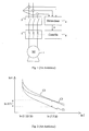
- a motor 1 is supplied by a three-phase electrical network, by via a circuit breaker 2 in series with a contactor 3.
- the protection device includes a trip unit 4. This performs various protection functions against overloads and short circuits, and more particularly a long protection function delay intended to cause the opening of the circuit breaker when the supply current of the motor measured by current transformers 5, exceeds a long delay threshold predetermined for a predetermined period.
- Trigger 4 also performs the SDTAM function and provides an opening signal A to a circuit 6 for controlling the contactor.
- a trigger signal, causing the opening of circuit breaker 2 is only produced if the overload persists for a period ( ⁇ T1) predetermined after the contactor open signal A. In normal operation, a overload therefore causes the contactor to open. If it opens, the overload disappears and the trip unit does not open the circuit breaker 2. The contactor can then be closed either manually or automatically for a restart attempt of the motor.
- the trigger 4 uses, to perform the SDTAM function, a C1 trigger curve (Figure 2) obtained by simply shifting the curve initial C2 trigger of the long delay function.
- Figure 3 shows a trigger known including SDTAM function.
- the trigger has a processing circuit 7 connected to current transformers 5 and having a first output connected to a relay 8 causing circuit breaker 2 to open when a trip signal D is given to it applied.
- the processing circuit 7 has a second output connected to the circuit 6 of contactor control and causing the contactor to open when an A1 signal contactor opening is produced.
- the processing circuit includes a circuit 9 performing a thermal function and producing a quantity ⁇ 1.
- the quantity ⁇ 1 is compared with a long delay threshold S LR , preferably corresponding to (1, 125Ir) 2 , by a comparator 10.
- the latter provides the output signal A1 of opening of the contactor when ⁇ 1 exceeds the threshold S LR .
- the output of comparator 10 is connected to the input of a counter 11 which introduces a time delay equal to the period ⁇ T1 between its input and its output.
- the output of the comparator 10 is also connected to an input (RESET) for resetting the counter to zero 11.
- a non-zero signal A1 is produced which causes the opening of the contactor 3 and the start of the counting by the counter 11.
- the opening of the contactor 3 causes the quantity ⁇ 1 to return to zero and, consequently, the signal A1.
- the falling edge of A1 resets counter 11 to zero so that no signal D is produced. If the contactor does not open, for example by bonding or short-circuiting its contacts or due to a fault in its control circuit or a failure in the connection between trip unit 4 and control circuit 6 or in the connection between the control circuit 6 and the contactor 3, the counting continues if the overload persists and a trip signal D is produced after the period ⁇ T1.
- circuits 9 and 10 can be performed by a bimetallic strip crossed by a current representative of the motor supply current.
- the circuit 9 may possibly be constituted by a thermal element.
- the curve C1 obtained by means of a bimetal strip is of the same type as the initial tripping curve C2 of the trigger.
- Ir being the trigger setting current
- such a curve represents, in logarithmic coordinates, the variations of time as a function of the current.
- a predetermined trigger threshold conventionally between 1.05Ir and 1.2Ir, preferably equal to 1.125Ir, it is considered that there is no overload.
- the current standards also recommend a predetermined maximum tripping time for a predetermined current value equal to 7.2Ir.
- the time axis between curves C1 and C2 is such that the curves are separated by ⁇ n ⁇ T1 for a current value of 7.2Ir.
- Curve C1 and C2 being parallel in coordinates logarithmic, for a given value of the current, their triggering instants are in fact separated by the period ⁇ T1 only for 7.2Ir.
- Curve C3 represents the curve of actual triggering obtained at the output of the counter 11 when the calculation circuit 9 uses the curve C1.
- FIG. 4 illustrates a particular embodiment of the processing circuit for a long delay trip device in relation with which the invention will be described later.
- the particular embodiment of Figure 4 has been described in French patent application No. 96 16 152 of the applicant, filed on 12/23/1996, which is incorporated by reference in the present application. It includes a square sampling and elevation circuit 12 receiving the current signals from the measuring transformers 5.
- the squares I k 2 of the current samples are applied to the input of a digital filter 13 with finite impulse response , or FIR filter.
- the output signals of the FIR filter 13 are representative of the square Ieff 2 of the rms value of the motor supply current.
- a digital filter 14 with infinite impulse response, or IIR filter is connected in series with the FIR filter.
- the IIR filter 14 receives the input Ieff 2 signals and outputs a quantity ⁇ 2 representative of the thermal state of the engine. This quantity ⁇ 2 is compared to the threshold S LR by the comparator 10 which provides a trigger signal D1 when ⁇ 2 is greater than or equal to the threshold S LR .
- the SDTAM function is added without modifying the determination of the quantity ⁇ 2 and, consequently, the production of the trigger signal D1, in accordance with a predetermined tripping curve C2.
- Figure 5 only the parts necessary for understanding have been represented.
- the square Ieff 2 of the effective value of the current is, as before, applied to the input of the IIR filter 14 and the quantity ⁇ 2 of the output of the filter 14 is compared by the comparator 10 at the threshold S LR to provide a trigger signal in accordance with the trigger curve C2.
- the trigger also comprises a circuit 15 for calculating a quantity ⁇ 3.
- the circuit 15 receives as input the signals Ieff 2 and en2.
- the quantity ⁇ 3 is then compared to the threshold S LR by a comparator 16 which supplies a signal A2 for command to open the contactor.
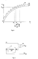
- the variations of ⁇ 2 as a function of time for a predetermined current Ieff, are illustrated in FIG. 6.
- ⁇ 3 Ieff 2 (1-e - (t + ⁇ T1) / ⁇ ) )
- the trigger curves C2 and C4 respectively obtained with the signals D1 and A2 in Figure 5 are shown in Figure 7.
- the trigger curve C2 is the desired curve and, as shown in Figure 6, the signal ⁇ 3 is permanence in advance of ⁇ T1 with respect to the signal ⁇ 2 so that the signal A2 reaches the threshold S LR with an advance of ⁇ T1 with respect to D1, whatever the value of the current.
- the trigger is a trigger of its own current, i.e. powered by current sensors.
- the interruption of current by opening contactor 3 interrupts supply to the trigger and, automatically reset signal D1.
- the signal osc3 may oscillate, especially in the area of the tripping curve close to the tripping threshold S LR where the tripping time is very long. Such oscillations when ⁇ 3 reaches the triggering threshold alter the period between the signals A2 and D1. This alteration is illustrated in FIG. 8 where the curve ⁇ 3 oscillates around the theoretical curve ⁇ 4 which it should take in accordance with FIG. 6. Thus, if a period ⁇ T1 effectively separates the instants t1 where ⁇ 2 reaches the threshold S LR and t2 where ⁇ 4 should have reached it, the curve ⁇ 3 actually reaches this threshold at an instant t3, which in the figure is located before t2. The period ⁇ T2 separating the emission of the signal A2, in t3, from the possible emission of the trigger signal D2, in t1, is then greater than the desired period ⁇ T1.
- a counter 17 is connected to the output of comparator 16 in FIG. 5.
- Counter 17 introduces the time delay ⁇ T1 and produces in response to a signal A2 a signal D2 after the time delay ⁇ T1.
- Signals D1 and D2 are applied to respective inputs of a OR logic circuit 18, the output of which provides the trigger signal D applied to the relay 8 and circuit breaker opening 2.
- the trigger signal D corresponds to signal D1 which corresponds exactly to the trigger curve C2 predetermined desired.
- a possible disturbance of the currents causes a alteration of the trigger curve C2 to maintain the ⁇ T1 period between signals A2 and D.
- the signals D1, D2 and D are actually produced only if the signal A2 does not cause the contactor to open and the motor supply to be interrupted. Otherwise, this interruption causes the interruption of the supply, at own current, of the trip unit and, in particular, of counter 17 and of OR circuit 18.
- signal A2 can be used to provide an alarm or to indicate that the fault is a thermal type fault, i.e. due to an overload.
- a microprocessor can perform, in whole or in part, the functions of filters 13 and 14, elevation or square, calculation circuits (15) and comparators (10, 16).
Landscapes
- Emergency Protection Circuit Devices (AREA)
- Protection Of Generators And Motors (AREA)
Applications Claiming Priority (2)
| Application Number | Priority Date | Filing Date | Title |
|---|---|---|---|
| FR9703569A FR2761209B1 (fr) | 1997-03-19 | 1997-03-19 | Dispositif de protection d'un moteur avec une fonction signal defaut thermique avance a la manoeuvre |
| FR9703569 | 1997-03-19 |
Publications (2)
| Publication Number | Publication Date |
|---|---|
| EP0866485A1 true EP0866485A1 (de) | 1998-09-23 |
| EP0866485B1 EP0866485B1 (de) | 2005-12-28 |
Family
ID=9505122
Family Applications (1)
| Application Number | Title | Priority Date | Filing Date |
|---|---|---|---|
| EP98410018A Expired - Lifetime EP0866485B1 (de) | 1997-03-19 | 1998-02-27 | Schutzvorrichtung für einen elektrischen Motor mit Fehlersignalisierung vor Aktivierung |
Country Status (4)
| Country | Link |
|---|---|
| EP (1) | EP0866485B1 (de) |
| DE (1) | DE69832916T2 (de) |
| ES (1) | ES2252820T3 (de) |
| FR (1) | FR2761209B1 (de) |
Cited By (4)
| Publication number | Priority date | Publication date | Assignee | Title |
|---|---|---|---|---|
| WO2000046896A1 (en) * | 1999-02-02 | 2000-08-10 | Nu-Lec Industries Pty Ltd | Protection relay for a circuit breaker |
| FR2802019A1 (fr) * | 1999-12-06 | 2001-06-08 | Schneider Electric Ind Sa | Relais de protection thermique |
| WO2007041162A2 (en) | 2005-09-30 | 2007-04-12 | Eaton Corporation | Protection apparatus for an electrical load |
| US10403116B2 (en) | 2017-06-20 | 2019-09-03 | General Electric Company | Electrical signature analysis of electrical rotating machines |
Families Citing this family (2)
| Publication number | Priority date | Publication date | Assignee | Title |
|---|---|---|---|---|
| DE102016118051A1 (de) * | 2016-09-23 | 2018-03-29 | Eaton Electrical Ip Gmbh & Co. Kg | Motorstarter |
| US10928814B2 (en) | 2017-02-24 | 2021-02-23 | General Electric Technology Gmbh | Autonomous procedure for monitoring and diagnostics of machine based on electrical signature analysis |
Citations (3)
| Publication number | Priority date | Publication date | Assignee | Title |
|---|---|---|---|---|
| FR2043743A1 (de) * | 1969-05-28 | 1971-02-19 | Westinghouse Electric Corp | |
| EP0135870A1 (de) * | 1983-09-27 | 1985-04-03 | BBC Aktiengesellschaft Brown, Boveri & Cie. | Verfahren und Vorrichtung zur Überlastsicherung elektrischer Leistungsverbraucher |
| DE3432476A1 (de) * | 1984-09-04 | 1986-03-13 | Siemens AG, 1000 Berlin und 8000 München | Schalterschuetz |
-
1997
- 1997-03-19 FR FR9703569A patent/FR2761209B1/fr not_active Expired - Fee Related
-
1998
- 1998-02-27 EP EP98410018A patent/EP0866485B1/de not_active Expired - Lifetime
- 1998-02-27 ES ES98410018T patent/ES2252820T3/es not_active Expired - Lifetime
- 1998-02-27 DE DE69832916T patent/DE69832916T2/de not_active Expired - Lifetime
Patent Citations (3)
| Publication number | Priority date | Publication date | Assignee | Title |
|---|---|---|---|---|
| FR2043743A1 (de) * | 1969-05-28 | 1971-02-19 | Westinghouse Electric Corp | |
| EP0135870A1 (de) * | 1983-09-27 | 1985-04-03 | BBC Aktiengesellschaft Brown, Boveri & Cie. | Verfahren und Vorrichtung zur Überlastsicherung elektrischer Leistungsverbraucher |
| DE3432476A1 (de) * | 1984-09-04 | 1986-03-13 | Siemens AG, 1000 Berlin und 8000 München | Schalterschuetz |
Cited By (7)
| Publication number | Priority date | Publication date | Assignee | Title |
|---|---|---|---|---|
| WO2000046896A1 (en) * | 1999-02-02 | 2000-08-10 | Nu-Lec Industries Pty Ltd | Protection relay for a circuit breaker |
| FR2802019A1 (fr) * | 1999-12-06 | 2001-06-08 | Schneider Electric Ind Sa | Relais de protection thermique |
| EP1107416A1 (de) * | 1999-12-06 | 2001-06-13 | Schneider Electric Industries SA | Thermisches Schutzrelais |
| US6563685B2 (en) | 1999-12-06 | 2003-05-13 | Schneider Electric Industries Sa | Thermal protection relay |
| WO2007041162A2 (en) | 2005-09-30 | 2007-04-12 | Eaton Corporation | Protection apparatus for an electrical load |
| EP1938355A4 (de) * | 2005-09-30 | 2011-07-20 | Eaton Corp | Schutzvorrichtung für eine elektrische last |
| US10403116B2 (en) | 2017-06-20 | 2019-09-03 | General Electric Company | Electrical signature analysis of electrical rotating machines |
Also Published As
| Publication number | Publication date |
|---|---|
| FR2761209A1 (fr) | 1998-09-25 |
| FR2761209B1 (fr) | 1999-06-11 |
| DE69832916D1 (de) | 2006-02-02 |
| EP0866485B1 (de) | 2005-12-28 |
| DE69832916T2 (de) | 2006-07-20 |
| ES2252820T3 (es) | 2006-05-16 |
Similar Documents
| Publication | Publication Date | Title |
|---|---|---|
| EP2849196B1 (de) | Verfahren zur Erkennung der Ursache eines Spannungsverlusts vor einem Trennschalter, Hilfsgerät für Trennschalter sowie elektrisches System, das einen solchen Trennschalter und ein solches Hilfsgerät umfasst | |
| EP0195693B1 (de) | Statische Auslöseeinheit für Leistungsschalter mit Abtastung und Blockierung des letzten Scheitelwerts des Signals | |
| EP0193449B1 (de) | Statische numerische Auslöseeinheit für Leistungsschalter mit optionellen Funktionen | |
| EP1466336A1 (de) | Verfahren zum feststellen von kontaktverschleiss eines elektrischen gerätes | |
| EP0194176A1 (de) | Statische numerische Auslöseeinheit für Leistungsschalter mit inverser Auslösezeitfunktion | |
| EP0193448A1 (de) | Statische Auslöseeinheit für Leistungsschalter mit parallel zu einer analogen Verarbeitungskette wirkender numerischer Verarbeitungskette | |
| CA1265194A (fr) | Circuit de protection d'alimentation a decoupage | |
| EP0193447A1 (de) | Statische numerische Auslöseeinheit für Leistungsschalter, ausgestattet mit einer Kalibrierungsschaltung | |
| EP1155488B1 (de) | Selektiver elektronischer auslöser | |
| BE897389A (fr) | Appareil d'actionnement commande par microprocesseur, | |
| FR2782190A1 (fr) | Procede et dispositif de declenchement d'un coupe-circuit a fusible pour un conducteur electrique dans un vehicule automobile | |
| EP1107416B1 (de) | Thermisches Schutzrelais | |
| EP0866485B1 (de) | Schutzvorrichtung für einen elektrischen Motor mit Fehlersignalisierung vor Aktivierung | |
| EP0859443B1 (de) | Schützrelais und Verfahren | |
| EP1318586B1 (de) | Vorrichtung und Verfahren zur elektrischen Kurzschlussdetektion und mit dieser Vorrichtung versehener Lastschalter | |
| EP2927928B1 (de) | Verfahren zur bestimmung einer überhitzung mindestens einer verbindungsklemme einer elektrischen vorrichtung, entsprechendes hilfsgerät und elektrisches system, das eine solche elektrische vorrichtung und ein solches hilfsgerät umfasst | |
| EP4016578B1 (de) | Diagnosevorrichtung für eine schaltung, entsprechendes schaltgerät und diagnoseverfahren | |
| EP0465384B1 (de) | Elektronischer Auslöser mit verbesserter Langzeitverzögerung | |
| EP0869597B1 (de) | Elektrische Überlastschutzanordnung mit kalten und warmen vorbestimmten Auslösezeiten | |
| EP3790034A1 (de) | Elektronisches hilfsschutzmodul und entsprechende schutzschaltervorrichtung | |
| EP0474565A1 (de) | Elektronischer Auslöser mit Kurzzeitverzögerung | |
| EP0851553B1 (de) | Elektronischer Auslöser mit, in Reihe geschalten, einem nichtrekursivem und einem rekursivem Filter | |
| FR2663473A1 (fr) | Dispositif et procede de limitation de charge pour appareil mecanique ou similaire, utilisant au moins un organe moteur de type electrique. | |
| WO2016131867A1 (fr) | Systeme de protection selective d'un reseau electrique et procede de protection associe | |
| FR2738086A1 (fr) | Circuit electronique de protection notamment pour alimentations electriques et automates programmables |
Legal Events
| Date | Code | Title | Description |
|---|---|---|---|
| PUAI | Public reference made under article 153(3) epc to a published international application that has entered the european phase |
Free format text: ORIGINAL CODE: 0009012 |
|
| AK | Designated contracting states |
Kind code of ref document: A1 Designated state(s): DE ES GB IT |
|
| AX | Request for extension of the european patent |
Free format text: AL;LT;LV;MK;RO;SI |
|
| 17P | Request for examination filed |
Effective date: 19990316 |
|
| AKX | Designation fees paid |
Free format text: DE ES GB IT |
|
| RBV | Designated contracting states (corrected) |
Designated state(s): DE ES GB IT |
|
| RAP1 | Party data changed (applicant data changed or rights of an application transferred) |
Owner name: SCHNEIDER ELECTRIC INDUSTRIES SA |
|
| RAP1 | Party data changed (applicant data changed or rights of an application transferred) |
Owner name: SCHNEIDER ELECTRIC INDUSTRIES SA |
|
| RAP1 | Party data changed (applicant data changed or rights of an application transferred) |
Owner name: SCHNEIDER ELECTRIC INDUSTRIES SAS |
|
| GRAP | Despatch of communication of intention to grant a patent |
Free format text: ORIGINAL CODE: EPIDOSNIGR1 |
|
| GRAS | Grant fee paid |
Free format text: ORIGINAL CODE: EPIDOSNIGR3 |
|
| GRAA | (expected) grant |
Free format text: ORIGINAL CODE: 0009210 |
|
| AK | Designated contracting states |
Kind code of ref document: B1 Designated state(s): DE ES GB IT |
|
| REG | Reference to a national code |
Ref country code: GB Ref legal event code: FG4D Free format text: NOT ENGLISH |
|
| REF | Corresponds to: |
Ref document number: 69832916 Country of ref document: DE Date of ref document: 20060202 Kind code of ref document: P |
|
| GBT | Gb: translation of ep patent filed (gb section 77(6)(a)/1977) |
Effective date: 20060208 |
|
| REG | Reference to a national code |
Ref country code: ES Ref legal event code: FG2A Ref document number: 2252820 Country of ref document: ES Kind code of ref document: T3 |
|
| PLBE | No opposition filed within time limit |
Free format text: ORIGINAL CODE: 0009261 |
|
| STAA | Information on the status of an ep patent application or granted ep patent |
Free format text: STATUS: NO OPPOSITION FILED WITHIN TIME LIMIT |
|
| 26N | No opposition filed |
Effective date: 20060929 |
|
| REG | Reference to a national code |
Ref country code: DE Ref legal event code: R084 Ref document number: 69832916 Country of ref document: DE Effective date: 20111228 |
|
| PGFP | Annual fee paid to national office [announced via postgrant information from national office to epo] |
Ref country code: ES Payment date: 20150113 Year of fee payment: 18 |
|
| PGFP | Annual fee paid to national office [announced via postgrant information from national office to epo] |
Ref country code: DE Payment date: 20160209 Year of fee payment: 19 Ref country code: IT Payment date: 20160222 Year of fee payment: 19 |
|
| PGFP | Annual fee paid to national office [announced via postgrant information from national office to epo] |
Ref country code: GB Payment date: 20160224 Year of fee payment: 19 |
|
| PG25 | Lapsed in a contracting state [announced via postgrant information from national office to epo] |
Ref country code: ES Free format text: LAPSE BECAUSE OF NON-PAYMENT OF DUE FEES Effective date: 20160228 |
|
| REG | Reference to a national code |
Ref country code: DE Ref legal event code: R119 Ref document number: 69832916 Country of ref document: DE |
|
| GBPC | Gb: european patent ceased through non-payment of renewal fee |
Effective date: 20170227 |
|
| PG25 | Lapsed in a contracting state [announced via postgrant information from national office to epo] |
Ref country code: DE Free format text: LAPSE BECAUSE OF NON-PAYMENT OF DUE FEES Effective date: 20170901 |
|
| PG25 | Lapsed in a contracting state [announced via postgrant information from national office to epo] |
Ref country code: GB Free format text: LAPSE BECAUSE OF NON-PAYMENT OF DUE FEES Effective date: 20170227 Ref country code: IT Free format text: LAPSE BECAUSE OF NON-PAYMENT OF DUE FEES Effective date: 20170227 |