EP0866537A2 - Limiteur de courant résitif à supraconducteur - Google Patents
Limiteur de courant résitif à supraconducteur Download PDFInfo
- Publication number
- EP0866537A2 EP0866537A2 EP98301663A EP98301663A EP0866537A2 EP 0866537 A2 EP0866537 A2 EP 0866537A2 EP 98301663 A EP98301663 A EP 98301663A EP 98301663 A EP98301663 A EP 98301663A EP 0866537 A2 EP0866537 A2 EP 0866537A2
- Authority
- EP
- European Patent Office
- Prior art keywords
- magnetic field
- current limiter
- superconducting
- superconducting element
- superconductor
- Prior art date
- Legal status (The legal status is an assumption and is not a legal conclusion. Google has not performed a legal analysis and makes no representation as to the accuracy of the status listed.)
- Granted
Links
Images
Classifications
-
- H—ELECTRICITY
- H01—ELECTRIC ELEMENTS
- H01F—MAGNETS; INDUCTANCES; TRANSFORMERS; SELECTION OF MATERIALS FOR THEIR MAGNETIC PROPERTIES
- H01F6/00—Superconducting magnets; Superconducting coils
- H01F6/02—Quenching; Protection arrangements during quenching
-
- H—ELECTRICITY
- H02—GENERATION; CONVERSION OR DISTRIBUTION OF ELECTRIC POWER
- H02H—EMERGENCY PROTECTIVE CIRCUIT ARRANGEMENTS
- H02H9/00—Emergency protective circuit arrangements for limiting excess current or voltage without disconnection
- H02H9/02—Emergency protective circuit arrangements for limiting excess current or voltage without disconnection responsive to excess current
- H02H9/023—Current limitation using superconducting elements
-
- H—ELECTRICITY
- H01—ELECTRIC ELEMENTS
- H01F—MAGNETS; INDUCTANCES; TRANSFORMERS; SELECTION OF MATERIALS FOR THEIR MAGNETIC PROPERTIES
- H01F6/00—Superconducting magnets; Superconducting coils
- H01F2006/001—Constructive details of inductive current limiters
-
- Y—GENERAL TAGGING OF NEW TECHNOLOGICAL DEVELOPMENTS; GENERAL TAGGING OF CROSS-SECTIONAL TECHNOLOGIES SPANNING OVER SEVERAL SECTIONS OF THE IPC; TECHNICAL SUBJECTS COVERED BY FORMER USPC CROSS-REFERENCE ART COLLECTIONS [XRACs] AND DIGESTS
- Y02—TECHNOLOGIES OR APPLICATIONS FOR MITIGATION OR ADAPTATION AGAINST CLIMATE CHANGE
- Y02E—REDUCTION OF GREENHOUSE GAS [GHG] EMISSIONS, RELATED TO ENERGY GENERATION, TRANSMISSION OR DISTRIBUTION
- Y02E40/00—Technologies for an efficient electrical power generation, transmission or distribution
- Y02E40/60—Superconducting electric elements or equipment; Power systems integrating superconducting elements or equipment
Definitions
- the present invention relates to a current limiter and in particular to a resistive superconducting current limiter.
- Current limiters can be grouped as resistive, inductive or hybrid, which operate by changing their impedance from nearly zero during normal operations to a current limiting value during fault conditions.
- the ideal performance characteristics of a fault current limiter include; zero impedance under normal operating conditions, high impedance under fault limiting conditions, fast transition from normal to fault limiting conditions, fast recovery to normal protection after interruption of a fault, high reliability over long periods with minimal maintenance, low volume, low weight and low cost.
- High temperature (HTC) or low temperature (LTC) offer attractive potential as fault current limiters due to the great contrast between the superconducting and non-superconducting states.
- High temperature superconductors are however inhomogenous, anistropic and brittle materials. Their use as fault current limiter encounters problems of local heating and mechanical failure when a fault current is applied.
- Resistive superconducting fault current limiters incorporate a superconducting element connected in series with the system to be protected. When the system is carrying normal operating current the element is in the superconducting state and thus has near zero resistance. The element is driven to the resistive state when a system fault occurs. The increase in current exceeds the critical current of the superconducting material which quenches to a resistive state. The impedance of the device (which is predominately resistive) increases rapidly providing the fault limiting effect.
- a problem with resistive superconducting fault limiters occurs if part of the superconducting element becomes resistive before the rest of the element. This is known as "local quenching" and is due to a non-uniformity of superconducting properties along the element length. The quenched part of the superconducting element overheats and may burn out leading to a catastrophic failure.
- triggering techniques include laser heating to exceed the critical temperature of the superconductor, discharging capacitors to exceed the critical current density of the superconductor and external sources of magnetic field to exceed the critical flux density of the superconductor.
- the triggering technique has to respond within a few milliseconds in order to limit the current before it reaches its peak value and must provide sufficient energy to quench the whole of the superconductor.
- British patent number 1,236,082 discloses a resistive superconducting fault current limiter which uses a low temperature metallic superconductor.
- a magnetic field produced by a helmholtz coil is used to quench the low temperature superconductor.
- a problem with this fault current limiter is that the magnetic field is radial and introduces an external Lorentz force on the superconducting elements. This arrangement is therefore unsuitable for use with high temperature superconductors as the Lorentz forces generated by the radial field would cause mechanical failure of the brittle high temperature superconductor elements.
- the present invention seeks to provide a triggering technique suitable for use with high temperature superconductors.
- a fault current limiter in accordance with the present invention solves the problem of local heating and mechanical fracture failure in superconductive elements.
- High temperature superconductors offer an attractive cost effective design due to the reduced cooling costs compared to low temperature metallic superconductors.
- the superconductive fault current limiter in accordance with the present invention has flexible design features to satisfy operating specifications by easily varying the physical, electrical and magnetic parameters. Uniform quenching of the superconductor is achieved by the combination of the critical current density and critical magnetic field intensity.
- the design has the advantage of being light weight, compact, high impedance ratio and can be easily upgraded to a higher rating fault current limiter.
- a resistive superconductive current limiter comprises a superconducting element maintained in a superconducting state when carrying an electrical current under normal operating conditions, and means for generating a magnetic field parallel to the superconducting element so that when a fault occurs the increase in the electrical current through the means for generating the magnetic field causes the magnetic field to be generated parallel to the superconducting element, the magnetic field generated exceeds the critical magnetic field density of the superconducting element to assist triggering of the transition of the superconducting element to a resistive state.
- the magnetic field is uniform which prevents local quenching which can cause thermal and mechanical failures due to local heating in high temperature superconductors.
- the application of a uniform magnetic field is also used to increase the rate of change of resistance of the superconductor, which in effect helps to produce a fast response fault current limiter.
- the uniform magnetic field parallel to the superconductor is generated by a winding through which an electrical current passes and which is preferably connected in series with the superconducting element.
- the winding is preferably a wound conductor foil of for example copper or aluminium.
- the winding is preferably connected in series with the superconducting element so that when a fault occurs the increase in electrical current through the winding causes a magnetic field to be generated which exceeds the critical magnetic field of the superconducting element.
- Foil windings are simple to produce and self-supporting.
- the production of the foil windings can be automated to produce a cost effective fault current limiter system.
- the superconducting element is located in a cryostat which is filled with a fluid at a temperature low enough to maintain it in the superconducting state.
- the cryostat is non-metallic and is placed within the winding.
- the superconducting element may be a non-inductively arranged set of resistive elements.
- means such as a reactor or resistor, is connected in parallel with the fault current limiter to limit the transient overvoltage in the superconducting element when in the resistive state.
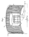
- figure 1 shows a partially broken away view of a fault current limiter in accordance with the present invention.
- a superconductive current limiter is generally indicated at 10.
- the superconducting element 12 consists of a non-inductively arranged (low self-field) resistor elements which are placed inside a non-metallic cryostat 14.
- the cryostat 14 is filled with a cooling medium such as liquid nitrogen which has a temperature low enough to maintain the superconducting element 12 in a superconductive state.
- the cryostat 14 is placed inside a conventional line winding 16, a foil winding, connected in series with the superconducting element 12.
- the superconducting element 12 is connected to the foil winding 16 by means of current leads 13 and 15.
- the pair of vertical current leads 13 and 15, each carry current in the opposite direction and are located inside the winding 16 in the region of predominately uniform magnetic field.
- the line winding 16 is a foil winding, of for example copper or aluminium, and provides a magnetic field parallel to the superconducting element 12.
- the magnetic field assists triggering and the number of turns in the foil winding 16 is selected to provide low inductance and low magnetic field when the superconducting element 12 is carrying its normal operating current.
- the increase in electrical current in the foil winding 16 causes a magnetic field to be generated parallel to the superconducting element 12 which exceeds the critical magnetic field of the superconducting element 12.
- the magnetic field produced by the foil winding 16 in combination with the increased current in the superconducting elements, triggers the superconducting element 12 to the resistive state.
- the magnetic field produced by the foil winding 16 is uniform and parallel to the superconducting element 12. It is used as a means of additional triggering and uniform quenching. Uniform quenching solves one of the acute problems of local quenching, which causes thermal and mechanical failures due to local heating in most high temperature superconductors used in power systems.
- the application of a uniform parallel field is also used to increase the rate of change of resistance of the superconducting elements 12, which in effect helps to produce a fast responding fault current limiter.
- This invention uses a foil winding 16, which is simple to produce and self-supporting and the production of the foil windings 16 can be automated to produce a cost effective fault current limiter system.
- a metal oxide varistor 18 is connected in parallel with the current limiter 10 in order to provide protection against the transient over-voltages and to assist in preventing excessive dissipation in the superconducting element 12.
- a superconducting current limiter 10 in accordance with the present invention is light weight, compact, fast, has lower losses, has lower overall cost and the impedance ratio is superior to other designs.
- the superconducting element 12 By arranging the superconducting element 12 in the non-inductive manner, the stored energy in the superconducting element 12 is greatly reduced. This means that power dissipation in the superconducting element 12 following a resistive transition is also greatly reduced.
- the foil winding 16 generates the magnetic field automatically when a fault occurs due to the increase in current through the foil winding 16. When the magnetic flux density exceeds the critical value it assists a uniform and fast quenching of the superconducting element 12.
Landscapes
- Engineering & Computer Science (AREA)
- Power Engineering (AREA)
- Containers, Films, And Cooling For Superconductive Devices (AREA)
- Emergency Protection Circuit Devices (AREA)
Applications Claiming Priority (3)
| Application Number | Priority Date | Filing Date | Title |
|---|---|---|---|
| GBGB9705717.8A GB9705717D0 (en) | 1997-03-19 | 1997-03-19 | Resistive superconducting current limiter |
| GB9705717 | 1997-03-19 | ||
| US09/037,737 US6137388A (en) | 1997-03-19 | 1998-03-10 | Resistive superconducting current limiter |
Publications (3)
| Publication Number | Publication Date |
|---|---|
| EP0866537A2 true EP0866537A2 (fr) | 1998-09-23 |
| EP0866537A3 EP0866537A3 (fr) | 1998-12-30 |
| EP0866537B1 EP0866537B1 (fr) | 2003-08-13 |
Family
ID=26311221
Family Applications (1)
| Application Number | Title | Priority Date | Filing Date |
|---|---|---|---|
| EP98301663A Revoked EP0866537B1 (fr) | 1997-03-19 | 1998-03-06 | Limiteur de courant résitif à supraconducteur |
Country Status (4)
| Country | Link |
|---|---|
| US (2) | US6137388A (fr) |
| EP (1) | EP0866537B1 (fr) |
| DE (1) | DE69817051T2 (fr) |
| GB (1) | GB9705717D0 (fr) |
Cited By (2)
| Publication number | Priority date | Publication date | Assignee | Title |
|---|---|---|---|---|
| ES2168969A1 (es) * | 2000-07-07 | 2002-06-16 | Consejo Superior Investigacion | Limitador de corriente inductivo con secundario hibrido de metal normal y superconductor de alta temperatura como interruptor controlado por corriente. |
| EP2230740A3 (fr) * | 2009-03-18 | 2012-12-05 | Nexans | Limitateur de courant supraconducteur doté d'un déclenchement de champ magnétique |
Families Citing this family (10)
| Publication number | Priority date | Publication date | Assignee | Title |
|---|---|---|---|---|
| GB9705717D0 (en) * | 1997-03-19 | 1997-05-07 | Rolls Royce Power Eng | Resistive superconducting current limiter |
| DE10035634A1 (de) * | 2000-07-21 | 2002-02-07 | Siemens Ag | Supraleitungseinrichtung mit induktiver Strombegrenzereinheit unter Verwendung von Hoch-Tc-Supraleitermaterial |
| JP2003141946A (ja) * | 2001-11-02 | 2003-05-16 | Sumitomo Electric Ind Ltd | 超電導ケーブル |
| US6920027B1 (en) | 2002-11-12 | 2005-07-19 | Felix Torres | Fast, variable, and reliable power system controller design |
| US6809910B1 (en) * | 2003-06-26 | 2004-10-26 | Superpower, Inc. | Method and apparatus to trigger superconductors in current limiting devices |
| KR101028817B1 (ko) * | 2005-05-25 | 2011-04-12 | 현대중공업 주식회사 | 무유도 권선형의 고온 초전도 전류 제한기 |
| US7333309B2 (en) * | 2005-06-02 | 2008-02-19 | Superpower, Inc | Self field triggered superconducting fault current limiter |
| KR100662754B1 (ko) * | 2005-12-02 | 2007-01-02 | 엘에스산전 주식회사 | 초전도 저항형 한류기 |
| US7484372B2 (en) * | 2006-03-06 | 2009-02-03 | Linde, Inc. | Multi-bath apparatus and method for cooling superconductors |
| ES2530575T3 (es) * | 2010-08-03 | 2015-03-03 | Alstom Technology Ltd | Un núcleo |
Family Cites Families (21)
| Publication number | Priority date | Publication date | Assignee | Title |
|---|---|---|---|---|
| AT272436B (de) * | 1967-04-10 | 1969-07-10 | Peter Dipl Ing Dr Techn Klaudy | Verfahren zum Überlastschutz unter Verwendung von Supraleitern |
| DE1932379C3 (de) * | 1969-06-26 | 1978-05-11 | Siemens Ag, 1000 Berlin Und 8000 Muenchen | Spule mit veränderlicher Induktivität als Strombegrenzungseinrichtung für Energieübertragungsanlagen |
| US3703664A (en) * | 1970-10-05 | 1972-11-21 | Ite Imperial Corp | Fault current limiter using superconductive element |
| CH586478A5 (fr) * | 1974-07-31 | 1977-03-31 | Siemens Ag | |
| FR2629956A1 (fr) * | 1988-04-07 | 1989-10-13 | Alsthom | Limiteur de courant |
| US4902995A (en) * | 1988-07-05 | 1990-02-20 | General Electric Company | Cable suspension system for cylindrical cryogenic vessels |
| GB2225164A (en) * | 1988-11-17 | 1990-05-23 | Marconi Co Ltd | Current limiting device |
| US4918409A (en) * | 1988-12-12 | 1990-04-17 | The Boeing Company | Ferrite device with superconducting magnet |
| FR2645278B1 (fr) * | 1989-04-04 | 1991-05-24 | Alsthom Gec | Dispositif de detection de transition supraconductrice et application a un limiteur de courant supraconducteur |
| EP0399481B1 (fr) * | 1989-05-22 | 1994-07-20 | Kabushiki Kaisha Toshiba | Dispositif de limitation de courant |
| EP0406636A1 (fr) * | 1989-07-04 | 1991-01-09 | Asea Brown Boveri Ag | Limiteur de courant avec supraconducteur |
| US5047741A (en) * | 1989-08-17 | 1991-09-10 | General Electric Company | Epoxy-impregnated superconductive tape coils |
| FR2655767A1 (fr) * | 1989-12-08 | 1991-06-14 | Alsthom Gec | Disjoncteur limiteur a courant continu a haute tension. |
| WO1991014287A1 (fr) * | 1990-03-05 | 1991-09-19 | E.I. Du Pont De Nemours And Company | Redresseur asservi pour supraconduction a haute temperature |
| FR2663475B2 (fr) * | 1990-04-24 | 1992-11-20 | Alsthom Gec | Limiteur de courant hybride. |
| FR2666912B1 (fr) * | 1990-09-14 | 1992-10-16 | Alsthom Gec | Dispositif limiteur de courant a supraconducteur. |
| JPH04359626A (ja) * | 1991-06-04 | 1992-12-11 | Tokyo Electric Power Co Inc:The | 限流装置 |
| DE69401722T2 (de) * | 1993-03-26 | 1997-07-03 | Ngk Insulators Ltd | Supraleitende Anordnung zur Fehlerstrombegrenzung |
| FR2704367B1 (fr) * | 1993-04-20 | 1995-05-24 | Gec Alsthom Electromec | Limiteur de courant supraconducteur à valeur de consigne réglable. |
| GB9506096D0 (en) * | 1995-03-24 | 1995-05-10 | Oxford Instr Public Limited Co | Current limiting device |
| GB9705717D0 (en) * | 1997-03-19 | 1997-05-07 | Rolls Royce Power Eng | Resistive superconducting current limiter |
-
1997
- 1997-03-19 GB GBGB9705717.8A patent/GB9705717D0/en active Pending
-
1998
- 1998-03-06 EP EP98301663A patent/EP0866537B1/fr not_active Revoked
- 1998-03-06 DE DE69817051T patent/DE69817051T2/de not_active Revoked
- 1998-03-10 US US09/037,737 patent/US6137388A/en not_active Expired - Fee Related
-
2000
- 2000-07-27 US US09/626,961 patent/US6433660B1/en not_active Expired - Fee Related
Cited By (2)
| Publication number | Priority date | Publication date | Assignee | Title |
|---|---|---|---|---|
| ES2168969A1 (es) * | 2000-07-07 | 2002-06-16 | Consejo Superior Investigacion | Limitador de corriente inductivo con secundario hibrido de metal normal y superconductor de alta temperatura como interruptor controlado por corriente. |
| EP2230740A3 (fr) * | 2009-03-18 | 2012-12-05 | Nexans | Limitateur de courant supraconducteur doté d'un déclenchement de champ magnétique |
Also Published As
| Publication number | Publication date |
|---|---|
| US6137388A (en) | 2000-10-24 |
| DE69817051D1 (de) | 2003-09-18 |
| GB9705717D0 (en) | 1997-05-07 |
| US6433660B1 (en) | 2002-08-13 |
| DE69817051T2 (de) | 2004-06-03 |
| EP0866537A3 (fr) | 1998-12-30 |
| EP0866537B1 (fr) | 2003-08-13 |
Similar Documents
| Publication | Publication Date | Title |
|---|---|---|
| US6664875B2 (en) | Matrix-type superconducting fault current limiter | |
| KR910003660B1 (ko) | 초전도 한류기(superconducting current limiting apparatus) | |
| KR100505054B1 (ko) | 초전도 저항형 한류기 | |
| KR102378965B1 (ko) | 초전도자석에서의 퀀칭 보호 | |
| CN100514791C (zh) | 电阻超导故障限流器 | |
| EP0935261B1 (fr) | Limiteur résistif de courant de défaut | |
| US4961066A (en) | Fault current limiter | |
| US4559576A (en) | Protection device for a superconducting magnetic coil assembly | |
| US6743984B2 (en) | Electrical power transmission system using superconductors | |
| US6137388A (en) | Resistive superconducting current limiter | |
| Schmidt et al. | Design and test of current limiting modules using YBCO-coated conductors | |
| WO1994003955A1 (fr) | Limiteur de courant de defaut supraconducteur a haute temperature | |
| EP0761030A1 (fr) | Limiteur de courant | |
| US6958893B2 (en) | Superconducting matrix fault current limiter with current-driven trigger mechanism | |
| US6809910B1 (en) | Method and apparatus to trigger superconductors in current limiting devices | |
| US20030191028A1 (en) | Superconducting device with inductive current limiter using a high-tc superconducting material | |
| US6344956B1 (en) | Oxide bulk superconducting current limiting element current | |
| CN102217160A (zh) | 故障电流超导限制器 | |
| US7440244B2 (en) | Self-triggering superconducting fault current limiter | |
| US6947265B2 (en) | Matrix current limiter with transformer configurations | |
| US7359164B2 (en) | Superconducting matrix fault current limiter with current-driven trigger mechanism | |
| Paul et al. | Superconducting fault current limiters based on high Tc superconductors | |
| Neumueller et al. | Economically viable fault current limiters using YBCO coated conductors | |
| WO2023191741A1 (fr) | Transformateur de limitation de courant de défaut supraconducteur | |
| RU63115U1 (ru) | Система электроснабжения и защиты электрических линий высокого напряжения |
Legal Events
| Date | Code | Title | Description |
|---|---|---|---|
| PUAI | Public reference made under article 153(3) epc to a published international application that has entered the european phase |
Free format text: ORIGINAL CODE: 0009012 |
|
| AK | Designated contracting states |
Kind code of ref document: A2 Designated state(s): CH DE FR GB LI SE |
|
| AX | Request for extension of the european patent |
Free format text: AL;LT;LV;MK;RO;SI |
|
| PUAL | Search report despatched |
Free format text: ORIGINAL CODE: 0009013 |
|
| AK | Designated contracting states |
Kind code of ref document: A3 Designated state(s): AT BE CH DE DK ES FI FR GB GR IE IT LI LU MC NL PT SE |
|
| AX | Request for extension of the european patent |
Free format text: AL;LT;LV;MK;RO;SI |
|
| 17P | Request for examination filed |
Effective date: 19981128 |
|
| AKX | Designation fees paid |
Free format text: CH DE FR GB LI SE |
|
| RAP1 | Party data changed (applicant data changed or rights of an application transferred) |
Owner name: ELIN SERVICE B.V. |
|
| RAP1 | Party data changed (applicant data changed or rights of an application transferred) |
Owner name: VA TECH ELIN SERVICE B.V. |
|
| 17Q | First examination report despatched |
Effective date: 20000619 |
|
| RAP1 | Party data changed (applicant data changed or rights of an application transferred) |
Owner name: VA TECH T & D NL B.V. |
|
| GRAG | Despatch of communication of intention to grant |
Free format text: ORIGINAL CODE: EPIDOS AGRA |
|
| GRAG | Despatch of communication of intention to grant |
Free format text: ORIGINAL CODE: EPIDOS AGRA |
|
| GRAH | Despatch of communication of intention to grant a patent |
Free format text: ORIGINAL CODE: EPIDOS IGRA |
|
| GRAH | Despatch of communication of intention to grant a patent |
Free format text: ORIGINAL CODE: EPIDOS IGRA |
|
| GRAA | (expected) grant |
Free format text: ORIGINAL CODE: 0009210 |
|
| AK | Designated contracting states |
Designated state(s): CH DE FR GB LI SE |
|
| PG25 | Lapsed in a contracting state [announced via postgrant information from national office to epo] |
Ref country code: LI Free format text: LAPSE BECAUSE OF NON-PAYMENT OF DUE FEES Effective date: 20030813 Ref country code: CH Free format text: LAPSE BECAUSE OF NON-PAYMENT OF DUE FEES Effective date: 20030813 |
|
| REG | Reference to a national code |
Ref country code: GB Ref legal event code: FG4D |
|
| REG | Reference to a national code |
Ref country code: CH Ref legal event code: EP |
|
| REF | Corresponds to: |
Ref document number: 69817051 Country of ref document: DE Date of ref document: 20030918 Kind code of ref document: P |
|
| REG | Reference to a national code |
Ref country code: SE Ref legal event code: TRGR |
|
| PGFP | Annual fee paid to national office [announced via postgrant information from national office to epo] |
Ref country code: GB Payment date: 20040225 Year of fee payment: 7 |
|
| PGFP | Annual fee paid to national office [announced via postgrant information from national office to epo] |
Ref country code: FR Payment date: 20040319 Year of fee payment: 7 Ref country code: CH Payment date: 20040319 Year of fee payment: 7 |
|
| PGFP | Annual fee paid to national office [announced via postgrant information from national office to epo] |
Ref country code: DE Payment date: 20040324 Year of fee payment: 7 |
|
| PGFP | Annual fee paid to national office [announced via postgrant information from national office to epo] |
Ref country code: SE Payment date: 20040329 Year of fee payment: 7 |
|
| PLBI | Opposition filed |
Free format text: ORIGINAL CODE: 0009260 |
|
| ET | Fr: translation filed | ||
| 26 | Opposition filed |
Opponent name: SIEMENS AG CORPORATE TECHNOLOGY Effective date: 20040512 |
|
| PLAX | Notice of opposition and request to file observation + time limit sent |
Free format text: ORIGINAL CODE: EPIDOSNOBS2 |
|
| PLAX | Notice of opposition and request to file observation + time limit sent |
Free format text: ORIGINAL CODE: EPIDOSNOBS2 |
|
| PLAX | Notice of opposition and request to file observation + time limit sent |
Free format text: ORIGINAL CODE: EPIDOSNOBS2 |
|
| PG25 | Lapsed in a contracting state [announced via postgrant information from national office to epo] |
Ref country code: GB Free format text: LAPSE BECAUSE OF NON-PAYMENT OF DUE FEES Effective date: 20050306 |
|
| PG25 | Lapsed in a contracting state [announced via postgrant information from national office to epo] |
Ref country code: SE Free format text: LAPSE BECAUSE OF NON-PAYMENT OF DUE FEES Effective date: 20050307 |
|
| PLAQ | Examination of admissibility of opposition: information related to despatch of communication + time limit deleted |
Free format text: ORIGINAL CODE: EPIDOSDOPE2 |
|
| PLAR | Examination of admissibility of opposition: information related to receipt of reply deleted |
Free format text: ORIGINAL CODE: EPIDOSDOPE4 |
|
| PLBQ | Unpublished change to opponent data |
Free format text: ORIGINAL CODE: EPIDOS OPPO |
|
| PLAB | Opposition data, opponent's data or that of the opponent's representative modified |
Free format text: ORIGINAL CODE: 0009299OPPO |
|
| R26 | Opposition filed (corrected) |
Opponent name: SIEMENS AG Effective date: 20040512 |
|
| RDAF | Communication despatched that patent is revoked |
Free format text: ORIGINAL CODE: EPIDOSNREV1 |
|
| EUG | Se: european patent has lapsed | ||
| REG | Reference to a national code |
Ref country code: CH Ref legal event code: PL |
|
| RDAG | Patent revoked |
Free format text: ORIGINAL CODE: 0009271 |
|
| STAA | Information on the status of an ep patent application or granted ep patent |
Free format text: STATUS: PATENT REVOKED |
|
| GBPC | Gb: european patent ceased through non-payment of renewal fee |
Effective date: 20050306 |
|
| REG | Reference to a national code |
Ref country code: FR Ref legal event code: ST Effective date: 20051130 |
|
| 27W | Patent revoked |
Effective date: 20050814 |
|
| PLAB | Opposition data, opponent's data or that of the opponent's representative modified |
Free format text: ORIGINAL CODE: 0009299OPPO |