EP0866547B1 - Elektrische Schaltung der Wicklung eines Reluktanzmotors - Google Patents
Elektrische Schaltung der Wicklung eines Reluktanzmotors Download PDFInfo
- Publication number
- EP0866547B1 EP0866547B1 EP98108754A EP98108754A EP0866547B1 EP 0866547 B1 EP0866547 B1 EP 0866547B1 EP 98108754 A EP98108754 A EP 98108754A EP 98108754 A EP98108754 A EP 98108754A EP 0866547 B1 EP0866547 B1 EP 0866547B1
- Authority
- EP
- European Patent Office
- Prior art keywords
- winding
- voltage
- windings
- rotor
- motor
- Prior art date
- Legal status (The legal status is an assumption and is not a legal conclusion. Google has not performed a legal analysis and makes no representation as to the accuracy of the status listed.)
- Expired - Lifetime
Links
Images

Classifications
-
- H—ELECTRICITY
- H02—GENERATION; CONVERSION OR DISTRIBUTION OF ELECTRIC POWER
- H02K—DYNAMO-ELECTRIC MACHINES
- H02K19/00—Synchronous motors or generators
- H02K19/02—Synchronous motors
- H02K19/10—Synchronous motors for multi-phase current
- H02K19/103—Motors having windings on the stator and a variable reluctance soft-iron rotor without windings
-
- H—ELECTRICITY
- H02—GENERATION; CONVERSION OR DISTRIBUTION OF ELECTRIC POWER
- H02K—DYNAMO-ELECTRIC MACHINES
- H02K1/00—Details of the magnetic circuit
- H02K1/06—Details of the magnetic circuit characterised by the shape, form or construction
- H02K1/12—Stationary parts of the magnetic circuit
- H02K1/14—Stator cores with salient poles
- H02K1/141—Stator cores with salient poles consisting of C-shaped cores
- H02K1/143—Stator cores with salient poles consisting of C-shaped cores of the horse-shoe type
-
- H—ELECTRICITY
- H02—GENERATION; CONVERSION OR DISTRIBUTION OF ELECTRIC POWER
- H02K—DYNAMO-ELECTRIC MACHINES
- H02K29/00—Motors or generators having non-mechanical commutating devices, e.g. discharge tubes or semiconductor devices
- H02K29/06—Motors or generators having non-mechanical commutating devices, e.g. discharge tubes or semiconductor devices with position sensing devices
- H02K29/08—Motors or generators having non-mechanical commutating devices, e.g. discharge tubes or semiconductor devices with position sensing devices using magnetic effect devices, e.g. Hall-plates, magneto-resistors
-
- H—ELECTRICITY
- H02—GENERATION; CONVERSION OR DISTRIBUTION OF ELECTRIC POWER
- H02K—DYNAMO-ELECTRIC MACHINES
- H02K7/00—Arrangements for handling mechanical energy structurally associated with dynamo-electric machines, e.g. structural association with mechanical driving motors or auxiliary dynamo-electric machines
- H02K7/14—Structural association with mechanical loads, e.g. with hand-held machine tools or fans
-
- H—ELECTRICITY
- H02—GENERATION; CONVERSION OR DISTRIBUTION OF ELECTRIC POWER
- H02P—CONTROL OR REGULATION OF ELECTRIC MOTORS, ELECTRIC GENERATORS OR DYNAMO-ELECTRIC CONVERTERS; CONTROLLING TRANSFORMERS, REACTORS OR CHOKE COILS
- H02P25/00—Arrangements or methods for the control of AC motors characterised by the kind of AC motor or by structural details
- H02P25/02—Arrangements or methods for the control of AC motors characterised by the kind of AC motor or by structural details characterised by the kind of motor
- H02P25/08—Reluctance motors
- H02P25/086—Commutation
- H02P25/089—Sensorless control
Definitions
- the invention relates to an electronically commutated DC motor with at least two angularly arranged in the direction of rotation of the motor, magnetic yokes that carry windings, the demagnetizing energy, that occurs when one of the windings is switched off, if this is switched off by the power source, by the yokes is mutually transferable with the aid of coupling diodes, the Self-induction voltage, which comes from a winding, at a connection point between this winding and a power semiconductor can be tapped to control the winding and in particular the electrical Circuit of an electronically commutated DC motor with at least two at an angle to each other in the direction of rotation of the motor, magnetically separated yokes that carry windings, the Demagnetizing energy when one of the windings is switched off arises. if this is switched off by the power source, by the yokes is mutually transferable with the aid of coupling diodes.
- U.S. Patent No. 5,214,365 describes an electronically commutated one Reluctance motor, in which the demagnetizing energy of a straight switched off winding is stored in a capacitor 19 and subsequently other windings via separate semiconductor switches is fed.
- the object of the invention is to provide simple circuits that for Operation of the above Motors are suitable, the recovery of the Demagnetization energy of the switched off phases without storage is possible.
- the electronically commutated reluctance motors according to the invention has long been compared to motors with permanent magnet excitation considered inferior because the magnetization energy of the yokes is not comes from permanent magnets, but every time the electromagnetic Poles should attract the rotor poles, electrically must be delivered.
- This energy is used according to the teaching of the invention cyclically recovered and transferred to the functionally following yoke, because the self-induction voltage Ua, which comes from the demagnetizing energy of a yoke 11Y, the subsequent yoke 11X is transmitted as bias energy.
- This will Energy savings (high efficiency) and a faster increase in Magnetic flux reached in the yokes, which are approaching rotor poles, the from the poles just switched off.
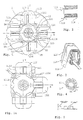
- FIG 1 shows an overall view of an engine according to the invention as none restrictive embodiment.
- the magnetic motor circuit consists of 2 horizontal U-shaped magnet yokes 11X and two vertical magnet yokes 11Y, the 4 yokes being identical.
- Each yoke has two poles 111, which are directed towards the rotor, which the Accept north or south polarity if through the main windings 112 or a current flows through the secondary windings 113.
- each yoke has at least one main winding 112.
- the motor magnetic circuit 1 thus consists of the wound yokes 11 each two cores 11X and 11Y, eight main windings 112 and possibly eight Secondary windings 113, together with the rotor 12.
- the rotor position detection circuit 3 which is the shutdown signal for the Windings of the X axis or the switch-on signal for that of the Y axis should deliver a rotor rotation of 30 degrees
- FIG. 4 consists of a multi-pole magnetic disc 32, which has six pairs of poles and on the rotor is attached, which moves in front of its fixed Hall sensor 31, which in its position for the purpose of finding an optimal working point, the Capacity control or to reverse the direction of rotation is adaptable. If the poles of the Magnetic disk 32 one behind the other in front of the Hall sensor 31 (with digital Output), a logic signal "low” or appears at its output "high”, depending on the rotor position, see FIG. 5.
- the control circuit 2 of the windings 112 and 113 consists mainly of two Power transistors (preferably MOSFET field effect transistors) 21X, 21Y, those in line with the main windings 112X, 112Y and the motor external power source are connected, see FIG. 6.
- Power transistors preferably MOSFET field effect transistors
- windings 112 or 113X (or Y), located on opposite yokes can be switched in series or in parallel, depending on the Voltage level at which the motor works.
- the transistors 21X and 21Y are push-pull by a simple one electronic circuit controlled by the rotor position detection circuit 3, so that when the output of the Hall sensor is "high", transistor 21X conducts, and transistor 21Y conducts when the Hall sensor output is low.
- the horizontal coiled yokes 11X and the vertical yokes 11Y become magnetized one after the other so that a rotating field appears at the poles 111 which sets the rotor in motion.
- the self-induction voltage Ua arises in the main winding 112X (as Source) and becomes the secondary windings 113Y of the vertical yokes as the receiver fed.
- the rotor 12 is made by repeating the above electromagnetic processes set in a continuous rotary motion, so that it makes one complete turn when each pair of yokes is six Receives control impulses.
- the switching point can be optimized practically by shifting the Hall sensors 31 take place opposite the yokes 11.
- the higher voltage required for the gate driving of the power transistors 21 is necessary by integrating the tips of the Self-induction voltage Ua can be obtained.
- FIG.1a which one 1 is an enlarged detail.
- FIGS. 1 and 1a are considered in connection with FIG. 6c, which is a Improvement and detailing of Fig. 6b represents.
- This distance must depend on the electromechanical parameters of each Motors can be optimized, and it is at least 3-4 times larger than that Air gap between the yokes 11 and the rotor 12 to avoid that by the direct contact between the yokes 11X and 11Y magnetic losses arise.
- 6c shows the complete circuit diagram of a functional motor, the dots next to windings 112 and 113 indicate their beginnings, and 112X e.g. B. represents the four main windings of the yokes 11X, which in Can be connected in series or in parallel.
- the Self-induction voltage Ua at the beginning of the secondary windings 113 hand off.
- the diodes 24 conduct the voltage peaks Ua to the capacitor 25, which is charged with a voltage after starting the motor is higher than the supply voltage Ubat and the supply of the Ensure control circuit of the gate electrodes of transistors 21Y, 21X This voltage is limited by the zener diode 26.
- the Hall sensor 31 When the switch 27 is closed, the Hall sensor 31 is energized set and at its digital output, which is connected to the gate electrode Transistors 21Y is connected, the logic signal appears “high” or “low”, respectively after whether there is a “north” or “south” pole of the multi-pole in front of the hall sensor Magnetic disk 32 is located.
- This logic signal is also applied to the signal inversion transistor 28, which applies the "low” signal to the gate electrode of transistor 21X, when the signal "high” is at the gate of transistor 21Y is.
- the arrow above the Hall sensor 31 shows that this compared to his Carrier is movable so that you can change the phase of the logic signals at the rotation of the multi-pole magnetic disk 32 can arise.
- the speed control of the motor can also be done without changing the phase of the Control signals occur by changing the supply voltage.
- the speed change can also be changed by changing the resistance of the Transistors 21, that is done by regulating the gate voltage.
- a two-stage regulation can be achieved by increasing the ohmic resistance of the engine, e.g. B. by separating one half of the parallel switched windings, s. Fig.6d.
- the windings 112, 112 'connected in parallel via the transistors 21, 21' are controlled at the same time when full power is required from the engine becomes. If a reduction in performance is desired, the Transistors 21 'are no longer driven, and so the winding 112' remains Business. The motor works with higher losses and a reduced one Power.
- 5b shows the control signals depending on the rotor rotation angle Transistors 21 and transistors 211, the self-induction voltage Ua traced.
- the output signal of the Hall sensor is on the abscissa of FIG. 5b shown, which corresponds to a rotor angle of 30 ° and the same Duration as the current pulse applied to the base of transistor 211Y becomes.
- the duration of the positive voltage pulses that the MOSFET transistors 21Y for The power regulation to be applied is on the lower abscissa in two Variants shown, this duration only reaches 30 ° at full load.
- the transistors 21 and 211 are activated simultaneously conductive, namely when the logic signal at the output of the Hall sensor from "low” changes to "high".
- transistor 21Y blocks before the Hall sensor closes again Logic signal "low” switches, ie before the rotor makes a 30 ° penetration.
- the blocking of the transistor 21 can e.g. by reaching one Limit value of the current or the speed (the commutation frequency) causes become.
- This type of control thus controls the transistors 21X, 21Y achieved depending on the rotor angle with a variable, reaching a maximum of 30 °, So no fixed 30 ° opening angle, as with the uncontrolled motors.
- the Energy supply i.e. the engine power, regulated.
- transistor 21Y The current conduction times of transistor 21Y are shown in bold, that of transistor 21X shown with a broken line.
- the electronic circuit 2 becomes a control voltage at the gate electrode one of the transistors 21, e.g. apolize to 21Y because at the exit of the Hall sensor 31 is a signal level "high” or "low” ahead.
- the Main winding 112Y is energized and moves rotor 12 out of the in Fig. 1 shown starting position by a 30 degree drain to Position in which the poles 111X - 121 match. So it comes from the Relative position of the poles with respect to the Y axis to a similar position, however, this is in relation to the X axis.
- this sine curve can also be phase-shifted, so that In this case there are two options for the commutation angle beeinfldorfen.
- the aforementioned influencing of the magnetic field can be practical can be achieved with the help of a winding or a permanent magnet be placed near the Hall sensor, with the winding a current flows that is almost constant.
- the reversal of direction can be achieved by changing the logic signal from FIG that transistor 21X becomes conductive when the logic signal of the Hall sensor is "high” instead of "low”, or by switching to another Hall sensor, which, however, is angularly shifted over the former.
- Self-control options for commutation such as the shutdown of a winding when the current that passes through it reaches a maximum or exceeds a predetermined value; if such a value during the normal motor operation is reached, this means that the rotor poles 121 already attracted to poles 111 belonging to this winding were.
- Switching off a winding takes place via the electronic Logic for switching on (possibly after a predetermined delay) the subsequent winding, e.g. 112Y.
- This cyclical control can in some cases be imposed from the outside be, with the motor at an externally predetermined speed is working.
- the transistors 21X, 214 are signals in this case controlled by a generator external to the engine.
- An asynchronous rotor can be used for this type of control (Squirrel-cage rotor) instead of the rotor described in FIG Be an advantage.
- the MOSFET transistors 21 also other semiconductors such as thyristors, (possibly via the gate can be switched off, i.e. GTO), bipolar transistors, etc. use, the electronic control circuit 2 as in the prior art known, is adjusted.
Landscapes
- Engineering & Computer Science (AREA)
- Power Engineering (AREA)
- Brushless Motors (AREA)
- Control Of Motors That Do Not Use Commutators (AREA)
- Synchronous Machinery (AREA)
- Iron Core Of Rotating Electric Machines (AREA)
- Control Of Electric Motors In General (AREA)
- Structures Of Non-Positive Displacement Pumps (AREA)
- Control Of Positive-Displacement Air Blowers (AREA)
- Toys (AREA)
- Reciprocating, Oscillating Or Vibrating Motors (AREA)
- Control Of Direct Current Motors (AREA)
Description
- Die Teile des elektromotorischen Kreises (den der Nutzdrenmoment erzeugt) fangen mit der Ziffer 1 an,
- die Teile des elektrischen Steuerkreises der Motorwicklungen fangen mit der Ziffer 2 an,
- die Teile des Kreises, die zur Ermittlung der Stellung der Rotorpole gegenüber der Pole des elektromagnetischen Erregerkreises dienen, fangen mit der Ziffer 3 an,
- die Teile des Magnetkreises, den der Rotor in einer Anlaufstellung bringt (ist nicht an allen Varianten vorhanden) fangen mit dem Ziffer 4 an.
- vor dem Motorstart werden in den Wicklungen elektrische Signale eingespeist, die abhängig von der Wicklungsinduktivität geändert werden, wobei erstere von der Rotorstellung abhängt, weil diese die Reluktanz (Induktivität) der Magnetkreise der betroffenen Joche bedingt.
- eine elektronische Logik vergleicht diese modifizierten Signale und ermittelt die Rotorstellung daraus, so daß am Ausgang dieser Schaltung ein Steuersignal des Transistors 21X oder 21Y erscheint,
- Die Wicklungen, die in Reihe mit dem leitenden Transistor liegen, werden angesteuert und versetzen den Rotor in Bewegung, der durch Einfluß aufmagnetisiert wird,
- wenn die so aufmagnetisierten Rotorpole sich den Polen der stromlosen Joche nähern, so wird in diese eine Spannung induziert, die von einem Schaltkreis ausgewertet wird, welcher diese Wicklung (Phase) die Nennspannung zuführt, sodaß der Rotor weiter angezogen wird.
Claims (7)
- Elektronisch kommutierter Gleichstrommotor mit mindestens zwei in Drehrichtung des Motors zueinander winklig angeordneten, magnetischen Jochen (11), die Wicklungen (112, 113) tragen, wobei die Entmagnetisierungsenergie, die bei Abschaltung einer der Wicklungen (112) entsteht, wenn diese von der Stromquelle abgeschaltet wird, von den Jochen (11) gegenseitig mit Hilfe von Koppeldioden (22) übertragbar ist, wobei die Selbstinduktionsspannung (Ua), die von einer Wicklung (112) stammt, an einer Verbindungsstelle zwischen dieser Wicklung und einem Leistungshalbleiter (21) zur Ansteuerung der Wicklung (112) abgreifbar ist, dadurch gekennzeichnet, daß auf den Jochen (11) neben den Wicklungen (112) Nebenwicklungen (113) angebracht sind, wobei die Selbstinduktionsspannung (Ua), die in der Wicklung (112) entsteht, welche auf dem ersten Joch (11) angebracht ist, über eine Koppeldiode (22) unmittelbar zu dem Anfang einer auf einem funktionell nachfolgenden Joch (11) angeordneten Nebenwicklung (113) leitbar ist.
- Motor nach Anspruch 1, dadurch gekennzeichnet, daß jeweils nicht mehr als ein Leistungshalbleiterschalter (21) in Reihe mit einer Wicklung (112) geschaltet ist.
- Motor nach Anspruch 1 oder 2, dadurch gekennzeichnet, daß die Selbstinduktionsspannung (Ua) ohne eine zeitliche Verzögerung bewirkende Zwischenspeicherung der Entmagnetisierungsenergie zu einer auf einem funktionell nachfolgenden Joch (11) angeordneten Nebenwicklung (113) leitbar ist.
- Motor nach Anspruch 3, dadurch gekennzeichnet, daß die beim Abschalten eines Leistungshalbleiterschalters (21) entstehende Selbstinduktionsspannung (Ua) während der Zeit, in welcher ein Rotorstellungssensor (31) seinen Logikzustand nicht ändert, mittels weiterer, steuerbarer Halbleiter (211) zu der Hauptwicklung (112), in der sie entstanden ist, zurückführbar ist.
- Motor nach Anspruch 4, dadurch gekennzeichnet, daß die Leistungshalbleiter (21, 211) einer Phase (X, Y) gleichzeitig leitend werden, die Sperrung der weiteren Halbleiter (211) jedoch erst mit der Änderung des Logikzustandes am Ausgang des Rotorstellungssensors (31) erfolgt:
- Motor nach Anspruch 4 oder 5, dadurch gekennzeichnet, daß die zum Ansteuern der Leistungshalbleiter (21) für eine Hauptwicklung (112, 113) erforderliche Spannung höher als die Nennspannung des Motors ist und aus der Selbstinduktionsspannung der Hauptwicklung (112) gewonnen wird.
- Motor nach Anspruch 6, dadurch gekennzeichnet, daß die Spitze der Selbstinduktionsspannung (Ua) in einem Kondensator (25) für die Gewinnung der Steuerungsspannung eines Leistungshalbleiters (21) speicherbar ist.
Applications Claiming Priority (5)
| Application Number | Priority Date | Filing Date | Title |
|---|---|---|---|
| RO9401551A RO117883B1 (ro) | 1994-09-22 | 1994-09-22 | Motor cu comutatie electronica, in special pentru pompe |
| RO9401551 | 1994-09-22 | ||
| RO9500800 | 1995-04-25 | ||
| RO9500800 | 1995-04-25 | ||
| EP95932980A EP0782781B1 (de) | 1994-09-22 | 1995-09-19 | Elektronisch geschalteter reluktanzmotor |
Related Parent Applications (2)
| Application Number | Title | Priority Date | Filing Date |
|---|---|---|---|
| EP95932980A Division EP0782781B1 (de) | 1994-09-22 | 1995-09-19 | Elektronisch geschalteter reluktanzmotor |
| EP95932980.6 Division | 1996-05-03 |
Publications (2)
| Publication Number | Publication Date |
|---|---|
| EP0866547A1 EP0866547A1 (de) | 1998-09-23 |
| EP0866547B1 true EP0866547B1 (de) | 2003-06-18 |
Family
ID=26653542
Family Applications (3)
| Application Number | Title | Priority Date | Filing Date |
|---|---|---|---|
| EP98108754A Expired - Lifetime EP0866547B1 (de) | 1994-09-22 | 1995-09-19 | Elektrische Schaltung der Wicklung eines Reluktanzmotors |
| EP98108755A Withdrawn EP0869601A3 (de) | 1994-09-22 | 1995-09-19 | Motoranordnung |
| EP95932980A Expired - Lifetime EP0782781B1 (de) | 1994-09-22 | 1995-09-19 | Elektronisch geschalteter reluktanzmotor |
Family Applications After (2)
| Application Number | Title | Priority Date | Filing Date |
|---|---|---|---|
| EP98108755A Withdrawn EP0869601A3 (de) | 1994-09-22 | 1995-09-19 | Motoranordnung |
| EP95932980A Expired - Lifetime EP0782781B1 (de) | 1994-09-22 | 1995-09-19 | Elektronisch geschalteter reluktanzmotor |
Country Status (11)
| Country | Link |
|---|---|
| US (1) | US6262510B1 (de) |
| EP (3) | EP0866547B1 (de) |
| JP (1) | JP3142575B2 (de) |
| KR (1) | KR970706640A (de) |
| CN (1) | CN1075272C (de) |
| AT (2) | ATE243386T1 (de) |
| BR (1) | BR9509072A (de) |
| DE (2) | DE59510727D1 (de) |
| ES (2) | ES2135768T3 (de) |
| RU (1) | RU2198459C2 (de) |
| WO (1) | WO1996009683A1 (de) |
Families Citing this family (84)
| Publication number | Priority date | Publication date | Assignee | Title |
|---|---|---|---|---|
| US6262510B1 (en) | 1994-09-22 | 2001-07-17 | Iancu Lungu | Electronically switched reluctance motor |
| BR9713519A (pt) * | 1996-11-20 | 2000-03-21 | Iancu Lungu | Máquina de relutância bifásica, comutada eletronicamente. |
| DE29622254U1 (de) * | 1996-12-21 | 1998-04-16 | Aeg Hausgeraete Gmbh | Leistungselektronik für einen Synchronmotor |
| US6129528A (en) * | 1998-07-20 | 2000-10-10 | Nmb Usa Inc. | Axial flow fan having a compact circuit board and impeller blade arrangement |
| US7064070B2 (en) * | 1998-09-28 | 2006-06-20 | Tokyo Electron Limited | Removal of CMP and post-CMP residue from semiconductors using supercritical carbon dioxide process |
| DE19851712C2 (de) * | 1998-10-30 | 2003-12-24 | Pascha Tavana-Nejad | Verfahren zur Speisung einer geschalteten Reluktanz- und Transversalflußmaschine |
| DE19860111A1 (de) * | 1998-12-23 | 2000-07-06 | Mannesmann Vdo Ag | Mehrpoliger Elektromotor und Verfahren zu seiner Herstellung |
| RO120022B1 (ro) * | 1999-05-26 | 2005-07-29 | Iancu Lungu | Inductor pentru maşini de reluctanţă comutabilă, cu două faze, cu comutaţie electronică |
| RO119917B1 (ro) * | 1999-05-26 | 2005-05-30 | Iancu Lungu | Metodă de reglare a puterii unei maşini de reluctanţă cu două faze, cu comutaţie electronică |
| CN1636308B (zh) * | 1999-05-26 | 2011-01-05 | 扬丘·伦古 | 用于控制电子换向的两相磁阻电机的方法 |
| DE50015473D1 (de) * | 1999-05-26 | 2009-01-15 | Lungu Jancu | Stator einer elektronisch kommutierten, zweiphasigen reluktanzmaschine |
| RO120023B1 (ro) * | 1999-05-26 | 2005-07-29 | Iancu Lungu | Motor electric de curent continuu, cu comutaţie electronică |
| JP2001050161A (ja) * | 1999-08-05 | 2001-02-23 | Ebara Corp | 気体移送機 |
| DE19941698A1 (de) | 1999-09-02 | 2001-03-15 | Bosch Gmbh Robert | Anordnung zum Schutz einer einen induktiven Verbraucher schaltenden Leistungshalbleiter-Endstufe |
| JP2001186693A (ja) * | 1999-12-27 | 2001-07-06 | Matsushita Refrig Co Ltd | スイッチトリラクタンスモータ |
| KR100693691B1 (ko) * | 2000-04-25 | 2007-03-09 | 동경 엘렉트론 주식회사 | 금속 필름의 침착방법 및 초임계 건조/세척 모듈을포함하는 금속침착 복합공정장치 |
| JP2002136090A (ja) * | 2000-10-30 | 2002-05-10 | Matsushita Electric Ind Co Ltd | ブラシレスモータ |
| JP2002262531A (ja) * | 2001-03-01 | 2002-09-13 | Toshio Takegawa | 直流発電機 |
| KR100429989B1 (ko) * | 2001-05-26 | 2004-05-03 | 엘지전자 주식회사 | 스켈리턴 타입 무정류자 전동기 |
| US6787951B2 (en) | 2001-10-01 | 2004-09-07 | Wavecrest Laboratories, Llc | Rotary electric motor having controller and power supply integrated therein |
| US6784582B1 (en) * | 2001-11-19 | 2004-08-31 | Valeo Electrical Systems, Inc. | Magnet shaping and pole concentration for reduction of cogging torque in permanent magnet motors |
| US6927524B2 (en) | 2001-11-27 | 2005-08-09 | Wavecrest Laboratories, Llc | Rotary electric motor having separate control modules for respective stator electromagnets |
| WO2003064065A1 (en) * | 2002-01-25 | 2003-08-07 | Supercritical Systems Inc. | Method for reducing the formation of contaminants during supercritical carbon dioxide processes |
| GB2422965B (en) * | 2002-02-04 | 2006-11-08 | Milwaukee Electric Tool Corp | Electrical devices including a switched reluctance motor |
| US7387868B2 (en) * | 2002-03-04 | 2008-06-17 | Tokyo Electron Limited | Treatment of a dielectric layer using supercritical CO2 |
| US7270941B2 (en) * | 2002-03-04 | 2007-09-18 | Tokyo Electron Limited | Method of passivating of low dielectric materials in wafer processing |
| US20050227187A1 (en) * | 2002-03-04 | 2005-10-13 | Supercritical Systems Inc. | Ionic fluid in supercritical fluid for semiconductor processing |
| JP4031440B2 (ja) * | 2002-03-22 | 2008-01-09 | 東京エレクトロン株式会社 | 超臨界処理を用いる汚染物の除去 |
| US7169540B2 (en) * | 2002-04-12 | 2007-01-30 | Tokyo Electron Limited | Method of treatment of porous dielectric films to reduce damage during cleaning |
| US6817845B2 (en) * | 2002-04-19 | 2004-11-16 | Envirotech Pumpsystems, Inc. | Centrifugal pump with switched reluctance motor drive |
| US6794839B1 (en) | 2002-11-08 | 2004-09-21 | Wavecrest Laboratories, Llc | Precision motor control with selective current waveform profiles in separate stator core segments |
| US6919700B2 (en) | 2003-01-29 | 2005-07-19 | Wavecrest Laboratories, Llc | Adaptive control of motor stator current waveform profiles |
| CA2483672A1 (en) * | 2002-06-19 | 2003-12-31 | Wavecrest Laboratories Llc | Adaptive control architecture for electric machines |
| US6940242B1 (en) | 2003-01-29 | 2005-09-06 | Wavecrest Laboratories, Llc | Motor control system for dynamically changing motor energization current waveform profiles |
| US6727668B1 (en) | 2002-06-19 | 2004-04-27 | Wavecrest Laboratories, Llc | Precision brushless motor control utilizing independent phase parameters |
| US20040112409A1 (en) * | 2002-12-16 | 2004-06-17 | Supercritical Sysems, Inc. | Fluoride in supercritical fluid for photoresist and residue removal |
| US20040177867A1 (en) * | 2002-12-16 | 2004-09-16 | Supercritical Systems, Inc. | Tetra-organic ammonium fluoride and HF in supercritical fluid for photoresist and residue removal |
| US20040231707A1 (en) * | 2003-05-20 | 2004-11-25 | Paul Schilling | Decontamination of supercritical wafer processing equipment |
| US20050022850A1 (en) * | 2003-07-29 | 2005-02-03 | Supercritical Systems, Inc. | Regulation of flow of processing chemistry only into a processing chamber |
| US7163380B2 (en) * | 2003-07-29 | 2007-01-16 | Tokyo Electron Limited | Control of fluid flow in the processing of an object with a fluid |
| US6986647B2 (en) * | 2003-11-21 | 2006-01-17 | Tokyo Electron Limited | Pump design for circulating supercritical carbon dioxide |
| DE102004028824B4 (de) * | 2004-06-15 | 2006-12-21 | Ebm-Papst Mulfingen Gmbh & Co. Kg | Gerät mit einer innerhalb eines Ventilators oder eines Elektromotors integriert angeordneten Steuerelektronik |
| US20060102282A1 (en) * | 2004-11-15 | 2006-05-18 | Supercritical Systems, Inc. | Method and apparatus for selectively filtering residue from a processing chamber |
| US20060185694A1 (en) * | 2005-02-23 | 2006-08-24 | Richard Brown | Rinsing step in supercritical processing |
| US20060185693A1 (en) * | 2005-02-23 | 2006-08-24 | Richard Brown | Cleaning step in supercritical processing |
| US20060186088A1 (en) * | 2005-02-23 | 2006-08-24 | Gunilla Jacobson | Etching and cleaning BPSG material using supercritical processing |
| US7550075B2 (en) * | 2005-03-23 | 2009-06-23 | Tokyo Electron Ltd. | Removal of contaminants from a fluid |
| US20060226117A1 (en) * | 2005-03-29 | 2006-10-12 | Bertram Ronald T | Phase change based heating element system and method |
| US20060223899A1 (en) * | 2005-03-30 | 2006-10-05 | Hillman Joseph T | Removal of porogens and porogen residues using supercritical CO2 |
| US20060219268A1 (en) * | 2005-03-30 | 2006-10-05 | Gunilla Jacobson | Neutralization of systemic poisoning in wafer processing |
| US7399708B2 (en) * | 2005-03-30 | 2008-07-15 | Tokyo Electron Limited | Method of treating a composite spin-on glass/anti-reflective material prior to cleaning |
| US7442636B2 (en) * | 2005-03-30 | 2008-10-28 | Tokyo Electron Limited | Method of inhibiting copper corrosion during supercritical CO2 cleaning |
| US20060225769A1 (en) * | 2005-03-30 | 2006-10-12 | Gentaro Goshi | Isothermal control of a process chamber |
| US20070000519A1 (en) * | 2005-06-30 | 2007-01-04 | Gunilla Jacobson | Removal of residues for low-k dielectric materials in wafer processing |
| JP4857631B2 (ja) * | 2005-07-15 | 2012-01-18 | 日本電産株式会社 | ファンモータ |
| RU2309517C1 (ru) * | 2006-02-07 | 2007-10-27 | Федеральное государственное унитарное предприятие "Центральный научно-исследовательский институт "Электроприбор" | Совмещенный вентильный индукторно-реактивный двигатель |
| US7436138B2 (en) * | 2006-03-01 | 2008-10-14 | Regal-Beloit Corporation | Methods and systems for emulating an induction motor utilizing an electronically commutated motor |
| DE102006012554A1 (de) * | 2006-03-16 | 2007-09-20 | Motec Components Gmbh & Co. Kg | Einphasiger geschalteter Reluktanzmotor |
| JP5188746B2 (ja) * | 2007-05-15 | 2013-04-24 | 株式会社甲府明電舎 | ブラシレスdcモータ |
| WO2008153832A2 (en) * | 2007-05-31 | 2008-12-18 | Krishnan Ramu | Switched reluctance machines with minimum stator core |
| EP2251959B1 (de) | 2009-05-15 | 2012-07-11 | Electric Drive Technology AG | Elektrische Spulengruppe und Verfahren zur Herstellung einer derartigen Spulengruppe |
| DE102010034890A1 (de) * | 2009-08-21 | 2011-03-10 | Johnson Electric S.A. | Universalmotor |
| DE102011009563A1 (de) * | 2010-01-30 | 2011-08-04 | ebm-papst St. Georgen GmbH & Co. KG, 78112 | Verfahren zur Verbesserung des Wirkungsgrades bei einem mehrphasigen Motor, und Motor zur Durchführung eines solchen Verfahrens |
| US8749104B2 (en) * | 2010-04-30 | 2014-06-10 | Alstom Renewable Technologies | Rotating electric machine, especially synchronous permanent magnet machine |
| DE102010036828A1 (de) | 2010-08-04 | 2012-02-09 | Friedrich Waltermann | Stator für elektrische Maschine mit überlappenden U-förmigen Kernblechen |
| DE102011052131A1 (de) | 2011-07-26 | 2013-01-31 | actiro Power Blower GmbH | Reluktanzmotor und verfahren zu dessen montage |
| CN103036492A (zh) * | 2011-10-05 | 2013-04-10 | 姚其良 | 外定子式直流电动机的工作程序控制编程 |
| GB2500580B (en) | 2012-03-23 | 2015-07-08 | Dyson Technology Ltd | Stator for an electrical machine |
| KR101367054B1 (ko) * | 2012-08-28 | 2014-02-24 | 삼성전기주식회사 | 스위치드 릴럭턴스 모터 어셈블리 |
| DE102012021351A1 (de) | 2012-11-02 | 2014-05-08 | Cornelius Lungu | Hi- Speed Sekundärluftpumpe |
| CN103178659B (zh) * | 2013-02-01 | 2015-05-13 | 江苏飞马动力科技有限公司 | 基于相位角控制的向量磁流电机 |
| DE102013102124A1 (de) * | 2013-03-04 | 2014-09-04 | Ebm-Papst St. Georgen Gmbh & Co. Kg | Einphasiger Elektromotor |
| TWM458027U (zh) * | 2013-03-12 | 2013-07-21 | Zhen-Jie Hong | 開關式磁阻馬達之改良構造 |
| CN103107669A (zh) * | 2013-03-13 | 2013-05-15 | 张家政 | 定子和转子凸极均为模块化的节能开关磁阻电机 |
| JP2018152923A (ja) | 2015-08-03 | 2018-09-27 | ヤマハ発動機株式会社 | ブラシモータ |
| CN105976972A (zh) * | 2016-06-21 | 2016-09-28 | 东莞力音电子有限公司 | 无骨架多串联线圈 |
| RU2696853C2 (ru) * | 2016-08-09 | 2019-08-07 | Рябых Виктор Владимирович | Электродвигатель |
| JP2018074811A (ja) * | 2016-10-31 | 2018-05-10 | 株式会社テージーケー | モータ装置 |
| CN108319758A (zh) * | 2017-12-29 | 2018-07-24 | 上海市政交通设计研究院有限公司 | 一种基于水力模型的城市下穿地道排水系统优化设计方法 |
| US10734876B2 (en) * | 2018-03-19 | 2020-08-04 | Denso International America, Inc. | Brushless motor for HVAC system |
| CN108233608B (zh) * | 2018-03-22 | 2023-09-15 | 宁德时代电机科技有限公司 | 一种集成无损自动制动的永磁电机装置 |
| KR102685318B1 (ko) * | 2018-08-01 | 2024-07-16 | 존슨 일렉트릭 인터내셔널 아게 | 액추에이터 |
| CN110515015A (zh) * | 2019-10-21 | 2019-11-29 | 贵州鑫湄纳米科技有限公司 | 一种新型微型磁传感器及其加工工艺 |
| KR102524011B1 (ko) * | 2020-11-30 | 2023-04-19 | 서울대학교산학협력단 | 전동기 장치 |
Family Cites Families (26)
| Publication number | Priority date | Publication date | Assignee | Title |
|---|---|---|---|---|
| US2109992A (en) | 1934-11-15 | 1938-03-01 | Gen Electric | Method of making current collecting devices |
| FR1401385A (fr) | 1964-04-20 | 1965-06-04 | Alsthom Cgee | Machine électrique à deux rotors |
| CH431701A (de) | 1965-04-30 | 1967-03-15 | Siemens Ag | Synchronmotor mit Reluktanzläufer |
| GB1198526A (en) | 1966-08-23 | 1970-07-15 | Licentia Gmbh | Motor having a Plurality of Speeds which can be Switched Selectively. |
| GB1292041A (en) | 1969-01-13 | 1972-10-11 | Lucas Industries Ltd | Full wave rectifier assemblies |
| US3842298A (en) * | 1973-04-06 | 1974-10-15 | Franklin Electric Co Inc | Submersible electric motor |
| DE3138323A1 (de) | 1981-09-25 | 1983-04-14 | Siemens AG, 1000 Berlin und 8000 München | Elektromotor, insbesondere kollektorloser gleichstrommotor |
| JPS59204451A (ja) * | 1983-05-09 | 1984-11-19 | Tokyo Electric Co Ltd | 電動機 |
| JPH0657242B2 (ja) * | 1984-06-25 | 1994-08-03 | 株式会社クラレ | 皮膚防護材 |
| US4644207A (en) | 1985-04-15 | 1987-02-17 | Rockwell International Corporation | Integrated dual pump system |
| JPS61244260A (ja) | 1985-04-22 | 1986-10-30 | Hideyo Hirai | 磁極と電機子を回転させる発電機 |
| JPS6311052A (ja) * | 1986-06-30 | 1988-01-18 | Secoh Giken Inc | 2相リラクタンス型半導体電動機 |
| FR2630868A1 (fr) | 1988-04-28 | 1989-11-03 | Sibeud Jean Paul | Dispositif electrique intercale entre un arbre moteur et un arbre recepteur notamment pour la transmission d'un vehicule lourd |
| US5015903A (en) | 1988-08-15 | 1991-05-14 | Pacific Scientific Company | Electronically commutated reluctance motor |
| DE68926503T2 (de) | 1988-10-07 | 1996-11-14 | Sekoh Giken Kk | Reluktanz-motor |
| DE69013324T2 (de) | 1989-08-28 | 1995-02-16 | Sekoh Giken Kk | Motor vom reluktanz-typ. |
| JPH03103091A (ja) | 1989-09-18 | 1991-04-30 | Secoh Giken Inc | 3相リラクタンス型電動機 |
| US5122697A (en) | 1990-04-30 | 1992-06-16 | Emerson Electric Co. | Hybrid single-phase variable reluctance motor |
| DE4024269A1 (de) | 1990-07-31 | 1992-02-13 | Born Sen Rainer | Elektrischer generator mit drehmomentwandlerfunktion |
| JPH04133646A (ja) | 1990-09-20 | 1992-05-07 | Secoh Giken Inc | 3相リラクタンス型電動機 |
| US5365137A (en) | 1990-11-01 | 1994-11-15 | Dynamic Systems International Inc. | Electric motor |
| DE4041805C1 (de) * | 1990-12-24 | 1992-10-08 | Erich 8500 Nuernberg De Rabe | |
| US5075610A (en) | 1991-03-28 | 1991-12-24 | Honeywell Inc. | Switched reluctance motor control circuit with energy recovery capability |
| KR960001954B1 (ko) | 1992-03-25 | 1996-02-08 | 엘지전자주식회사 | 스위치드 릴럭턴스 모터 |
| JP2936886B2 (ja) * | 1992-04-30 | 1999-08-23 | 松下電器産業株式会社 | 永久磁石電動機の回転子 |
| US6262510B1 (en) | 1994-09-22 | 2001-07-17 | Iancu Lungu | Electronically switched reluctance motor |
-
1995
- 1995-09-15 US US08/809,238 patent/US6262510B1/en not_active Expired - Fee Related
- 1995-09-19 CN CN95195804A patent/CN1075272C/zh not_active Expired - Fee Related
- 1995-09-19 WO PCT/RO1995/000012 patent/WO1996009683A1/de not_active Ceased
- 1995-09-19 JP JP08510786A patent/JP3142575B2/ja not_active Expired - Fee Related
- 1995-09-19 BR BR9509072A patent/BR9509072A/pt not_active IP Right Cessation
- 1995-09-19 AT AT98108754T patent/ATE243386T1/de not_active IP Right Cessation
- 1995-09-19 AT AT95932980T patent/ATE182040T1/de not_active IP Right Cessation
- 1995-09-19 DE DE59510727T patent/DE59510727D1/de not_active Expired - Lifetime
- 1995-09-19 EP EP98108754A patent/EP0866547B1/de not_active Expired - Lifetime
- 1995-09-19 ES ES95932980T patent/ES2135768T3/es not_active Expired - Lifetime
- 1995-09-19 EP EP98108755A patent/EP0869601A3/de not_active Withdrawn
- 1995-09-19 DE DE59506367T patent/DE59506367D1/de not_active Expired - Lifetime
- 1995-09-19 RU RU97106100/09A patent/RU2198459C2/ru not_active IP Right Cessation
- 1995-09-19 ES ES98108754T patent/ES2202696T3/es not_active Expired - Lifetime
- 1995-09-19 EP EP95932980A patent/EP0782781B1/de not_active Expired - Lifetime
- 1995-09-19 KR KR1019970701883A patent/KR970706640A/ko not_active Abandoned
Also Published As
| Publication number | Publication date |
|---|---|
| KR970706640A (ko) | 1997-11-03 |
| CN1075272C (zh) | 2001-11-21 |
| DE59506367D1 (de) | 1999-08-12 |
| US6262510B1 (en) | 2001-07-17 |
| JPH10505998A (ja) | 1998-06-09 |
| ATE243386T1 (de) | 2003-07-15 |
| ATE182040T1 (de) | 1999-07-15 |
| RU2198459C2 (ru) | 2003-02-10 |
| JP3142575B2 (ja) | 2001-03-07 |
| DE59510727D1 (de) | 2003-07-24 |
| CN1161764A (zh) | 1997-10-08 |
| BR9509072A (pt) | 1997-12-23 |
| ES2202696T3 (es) | 2004-04-01 |
| EP0869601A3 (de) | 1998-10-21 |
| EP0782781B1 (de) | 1999-07-07 |
| ES2135768T3 (es) | 1999-11-01 |
| EP0782781A1 (de) | 1997-07-09 |
| EP0866547A1 (de) | 1998-09-23 |
| EP0869601A2 (de) | 1998-10-07 |
| WO1996009683A1 (de) | 1996-03-28 |
Similar Documents
| Publication | Publication Date | Title |
|---|---|---|
| EP0866547A1 (de) | Elektrische Schaltung der Wicklung eines Reluktanzmotors | |
| DE2813784C2 (de) | ||
| DE69533104T4 (de) | Bürstenloser gleichstrommotor mit vorgezogener phasensynchronisierung | |
| DE69219812T2 (de) | Steuerschaltung mit Energierückgewinnung für einen Reluktanzmotor | |
| EP1851847B1 (de) | Verfahren zum betrieb eines zweisträngigen elektronisch kommutierten motors, und motor zur durchführung eines solchen verfahrens | |
| DE60007878T2 (de) | Ansteuerung einer elektrischen reluktanz maschine | |
| EP2025054A1 (de) | Verfahren zum betrieb eines elektronisch kommutierten motors, und motor zur durchführung eines solchen verfahrens | |
| DE2527041A1 (de) | Buerstenloser gleichstrommotor | |
| DE2205238A1 (de) | Elektronische Steuervorrichtung, insbesondere für einen Motor mit veränderlichem magnetischem Widerstand | |
| DE2211780A1 (de) | Schaltvorrichtung für einen Synchronmotor mit einer Erregungswicklung und einer Ausgangsachse | |
| DE2600422A1 (de) | Phasenzahl- und frequenz-umformer | |
| DE2457838A1 (de) | Wechselstrommotor-steller | |
| DE3819064C2 (de) | ||
| DE2031141A1 (de) | Kommutator-Motor mit einem Dauermagnetläufer | |
| EP0583328B1 (de) | Elektronische steuerschaltung für die speisung von ohmisch-induktiven lasten durch gleichstromimpulse | |
| DE1135083B (de) | Kollektorloser mit Unterbrecherkontakten steuerbarer elektrischer Gleichstrommotor mit einem Rotor aus Dauermagnetwerkstoff | |
| DE2263242A1 (de) | Kollektorloser gleichstrommotor | |
| DE2839712B2 (de) | Schaltung mit Zerhackerfunktion für einen bürstenlosen Gleichstrommotor | |
| DE102007024354A1 (de) | Verfahren zum Betrieb eines elektronisch kommutierten Motors, und Motor zur Durchführung eines solchen Verfahrens | |
| DE102006013013B9 (de) | Kraft-Erzeuger-Einheit | |
| DE19534727A1 (de) | Geschalteter Reluktanzmotor | |
| EP1485987A1 (de) | Mehrphasiger kollektorloser gleichstrommotor | |
| DE3932762A1 (de) | Elektronisch kommutierte gleichstrommaschine | |
| EP1101268A1 (de) | Verfahren und schaltungen zur leistungsregelung einer elektronisch kommutierten, zweiphasigen reluktanzmaschine | |
| DE102012100208A1 (de) | Verbesserter Elektromotor |
Legal Events
| Date | Code | Title | Description |
|---|---|---|---|
| PUAI | Public reference made under article 153(3) epc to a published international application that has entered the european phase |
Free format text: ORIGINAL CODE: 0009012 |
|
| AC | Divisional application: reference to earlier application |
Ref document number: 782781 Country of ref document: EP |
|
| AK | Designated contracting states |
Kind code of ref document: A1 Designated state(s): AT BE CH DE DK ES FR GB GR IE IT LI LU MC NL PT SE |
|
| 17P | Request for examination filed |
Effective date: 19980903 |
|
| 17Q | First examination report despatched |
Effective date: 20000711 |
|
| GRAG | Despatch of communication of intention to grant |
Free format text: ORIGINAL CODE: EPIDOS AGRA |
|
| GRAG | Despatch of communication of intention to grant |
Free format text: ORIGINAL CODE: EPIDOS AGRA |
|
| GRAH | Despatch of communication of intention to grant a patent |
Free format text: ORIGINAL CODE: EPIDOS IGRA |
|
| GRAH | Despatch of communication of intention to grant a patent |
Free format text: ORIGINAL CODE: EPIDOS IGRA |
|
| GRAA | (expected) grant |
Free format text: ORIGINAL CODE: 0009210 |
|
| AC | Divisional application: reference to earlier application |
Ref document number: 0782781 Country of ref document: EP Kind code of ref document: P |
|
| AK | Designated contracting states |
Designated state(s): AT BE CH DE DK ES FR GB GR IE IT LI LU MC NL PT SE |
|
| PG25 | Lapsed in a contracting state [announced via postgrant information from national office to epo] |
Ref country code: NL Free format text: LAPSE BECAUSE OF FAILURE TO SUBMIT A TRANSLATION OF THE DESCRIPTION OR TO PAY THE FEE WITHIN THE PRESCRIBED TIME-LIMIT Effective date: 20030618 Ref country code: IE Free format text: LAPSE BECAUSE OF FAILURE TO SUBMIT A TRANSLATION OF THE DESCRIPTION OR TO PAY THE FEE WITHIN THE PRESCRIBED TIME-LIMIT Effective date: 20030618 |
|
| REG | Reference to a national code |
Ref country code: GB Ref legal event code: FG4D Free format text: NOT ENGLISH |
|
| REG | Reference to a national code |
Ref country code: CH Ref legal event code: EP |
|
| REG | Reference to a national code |
Ref country code: IE Ref legal event code: FG4D Free format text: GERMAN |
|
| REF | Corresponds to: |
Ref document number: 59510727 Country of ref document: DE Date of ref document: 20030724 Kind code of ref document: P |
|
| GBT | Gb: translation of ep patent filed (gb section 77(6)(a)/1977) |
Effective date: 20030728 |
|
| PG25 | Lapsed in a contracting state [announced via postgrant information from national office to epo] |
Ref country code: SE Free format text: LAPSE BECAUSE OF FAILURE TO SUBMIT A TRANSLATION OF THE DESCRIPTION OR TO PAY THE FEE WITHIN THE PRESCRIBED TIME-LIMIT Effective date: 20030918 Ref country code: PT Free format text: LAPSE BECAUSE OF FAILURE TO SUBMIT A TRANSLATION OF THE DESCRIPTION OR TO PAY THE FEE WITHIN THE PRESCRIBED TIME-LIMIT Effective date: 20030918 Ref country code: GR Free format text: LAPSE BECAUSE OF FAILURE TO SUBMIT A TRANSLATION OF THE DESCRIPTION OR TO PAY THE FEE WITHIN THE PRESCRIBED TIME-LIMIT Effective date: 20030918 Ref country code: DK Free format text: LAPSE BECAUSE OF FAILURE TO SUBMIT A TRANSLATION OF THE DESCRIPTION OR TO PAY THE FEE WITHIN THE PRESCRIBED TIME-LIMIT Effective date: 20030918 |
|
| PG25 | Lapsed in a contracting state [announced via postgrant information from national office to epo] |
Ref country code: LU Free format text: LAPSE BECAUSE OF NON-PAYMENT OF DUE FEES Effective date: 20030919 Ref country code: GB Free format text: LAPSE BECAUSE OF NON-PAYMENT OF DUE FEES Effective date: 20030919 Ref country code: AT Free format text: LAPSE BECAUSE OF NON-PAYMENT OF DUE FEES Effective date: 20030919 |
|
| PG25 | Lapsed in a contracting state [announced via postgrant information from national office to epo] |
Ref country code: MC Free format text: LAPSE BECAUSE OF NON-PAYMENT OF DUE FEES Effective date: 20030930 Ref country code: LI Free format text: LAPSE BECAUSE OF NON-PAYMENT OF DUE FEES Effective date: 20030930 Ref country code: CH Free format text: LAPSE BECAUSE OF NON-PAYMENT OF DUE FEES Effective date: 20030930 Ref country code: BE Free format text: LAPSE BECAUSE OF NON-PAYMENT OF DUE FEES Effective date: 20030930 |
|
| NLV1 | Nl: lapsed or annulled due to failure to fulfill the requirements of art. 29p and 29m of the patents act | ||
| REG | Reference to a national code |
Ref country code: IE Ref legal event code: FD4D |
|
| ET | Fr: translation filed | ||
| BERE | Be: lapsed |
Owner name: *LUNGU IANCU Effective date: 20030930 |
|
| REG | Reference to a national code |
Ref country code: ES Ref legal event code: FG2A Ref document number: 2202696 Country of ref document: ES Kind code of ref document: T3 |
|
| PGFP | Annual fee paid to national office [announced via postgrant information from national office to epo] |
Ref country code: ES Payment date: 20040422 Year of fee payment: 9 |
|
| PLBE | No opposition filed within time limit |
Free format text: ORIGINAL CODE: 0009261 |
|
| STAA | Information on the status of an ep patent application or granted ep patent |
Free format text: STATUS: NO OPPOSITION FILED WITHIN TIME LIMIT |
|
| GBPC | Gb: european patent ceased through non-payment of renewal fee |
Effective date: 20030919 |
|
| REG | Reference to a national code |
Ref country code: CH Ref legal event code: PL |
|
| 26N | No opposition filed |
Effective date: 20040319 |
|
| PG25 | Lapsed in a contracting state [announced via postgrant information from national office to epo] |
Ref country code: ES Free format text: LAPSE BECAUSE OF NON-PAYMENT OF DUE FEES Effective date: 20040920 |
|
| PG25 | Lapsed in a contracting state [announced via postgrant information from national office to epo] |
Ref country code: IT Free format text: LAPSE BECAUSE OF NON-PAYMENT OF DUE FEES;WARNING: LAPSES OF ITALIAN PATENTS WITH EFFECTIVE DATE BEFORE 2007 MAY HAVE OCCURRED AT ANY TIME BEFORE 2007. THE CORRECT EFFECTIVE DATE MAY BE DIFFERENT FROM THE ONE RECORDED. Effective date: 20050919 |
|
| REG | Reference to a national code |
Ref country code: ES Ref legal event code: FD2A Effective date: 20040920 |
|
| PGFP | Annual fee paid to national office [announced via postgrant information from national office to epo] |
Ref country code: FR Payment date: 20060920 Year of fee payment: 12 |
|
| REG | Reference to a national code |
Ref country code: FR Ref legal event code: ST Effective date: 20061130 |
|
| PG25 | Lapsed in a contracting state [announced via postgrant information from national office to epo] |
Ref country code: FR Free format text: LAPSE BECAUSE OF NON-PAYMENT OF DUE FEES Effective date: 20040930 |
|
| REG | Reference to a national code |
Ref country code: DE Ref legal event code: R082 Ref document number: 59510727 Country of ref document: DE Representative=s name: DURM & PARTNER PATENTANWAELTE, DE |
|
| REG | Reference to a national code |
Ref country code: DE Ref legal event code: R082 Ref document number: 59510727 Country of ref document: DE Representative=s name: DURM & PARTNER PATENTANWAELTE, DE Effective date: 20110822 Ref country code: DE Ref legal event code: R081 Ref document number: 59510727 Country of ref document: DE Owner name: ELECTRIC DRIVE TECHNOLOGY AG, CH Free format text: FORMER OWNER: LUNGU, IANCU, BUKAREST/BUCURESTI, RO Effective date: 20110822 |
|
| PGFP | Annual fee paid to national office [announced via postgrant information from national office to epo] |
Ref country code: DE Payment date: 20121126 Year of fee payment: 18 |
|
| REG | Reference to a national code |
Ref country code: DE Ref legal event code: R119 Ref document number: 59510727 Country of ref document: DE |
|
| REG | Reference to a national code |
Ref country code: DE Ref legal event code: R079 Ref document number: 59510727 Country of ref document: DE Free format text: PREVIOUS MAIN CLASS: H02P0005050000 Ipc: H02P0025080000 |
|
| REG | Reference to a national code |
Ref country code: DE Ref legal event code: R119 Ref document number: 59510727 Country of ref document: DE Effective date: 20140401 Ref country code: DE Ref legal event code: R079 Ref document number: 59510727 Country of ref document: DE Free format text: PREVIOUS MAIN CLASS: H02P0005050000 Ipc: H02P0025080000 Effective date: 20140606 |
|
| PG25 | Lapsed in a contracting state [announced via postgrant information from national office to epo] |
Ref country code: DE Free format text: LAPSE BECAUSE OF NON-PAYMENT OF DUE FEES Effective date: 20140401 |