EP0866636A2 - Bobine mobile et méthode pour sa fabrication - Google Patents
Bobine mobile et méthode pour sa fabrication Download PDFInfo
- Publication number
- EP0866636A2 EP0866636A2 EP98104667A EP98104667A EP0866636A2 EP 0866636 A2 EP0866636 A2 EP 0866636A2 EP 98104667 A EP98104667 A EP 98104667A EP 98104667 A EP98104667 A EP 98104667A EP 0866636 A2 EP0866636 A2 EP 0866636A2
- Authority
- EP
- European Patent Office
- Prior art keywords
- voice coil
- membrane
- former
- centering
- strands
- Prior art date
- Legal status (The legal status is an assumption and is not a legal conclusion. Google has not performed a legal analysis and makes no representation as to the accuracy of the status listed.)
- Ceased
Links
Images


Classifications
-
- H—ELECTRICITY
- H04—ELECTRIC COMMUNICATION TECHNIQUE
- H04R—LOUDSPEAKERS, MICROPHONES, GRAMOPHONE PICK-UPS OR LIKE ACOUSTIC ELECTROMECHANICAL TRANSDUCERS; ELECTRIC HEARING AIDS; PUBLIC ADDRESS SYSTEMS
- H04R9/00—Transducers of moving-coil, moving-strip, or moving-wire type
- H04R9/02—Details
- H04R9/04—Construction, mounting, or centering of coil
- H04R9/046—Construction
Definitions
- the invention is concerned with the formation and manufacture of voice coil arrangements, with a particular emphasis on reducing the weight of such arrangements.
- Voice coil arrangements in the sense of this application essentially comprise one Voice coil former with voice coil, a centering membrane and strands.
- The is in As a rule, tubular voice coil carriers are connected to the voice coil.
- the centering diaphragm is arranged at an axial distance from the voice coil and also with connected to the voice coil former by means of an adhesive seam.
- the centering membrane which extends radially to the longitudinal extent of the voice coil bobbin, depending on the training either an accordion or wavy contour.
- the two voice coil wires of the voice coil are each conductive via a soldering point with one of the two strands connected.
- Loudspeaker manufacturing For the formation of voice coil arrangements, which are often used as a prefabricated part Loudspeaker manufacturing have been used in the prior art developed two main manufacturing processes.
- the voice coil is first placed on the carrier wrapped and baked and then the inside diameter of the neck of the membrane connected to the outer diameter of the voice coil former. Unless the voice coil wires before connecting the membrane to the voice coil former were soldered to the strands, they are now connected to the strands via the soldering points. Then, after applying a bead of adhesive to the neck of the membrane, the Centering membrane pushed over the voice coil and with the outer diameter of the Neck of the membrane glued. If the soldering points are not already before the opening of the Centering membrane were glued to the bottom, they are now to the bottom of the Membrane glued.
- the voice coil with the Voice coil former and the voice coil wires over the soldering points with the strands connected the voice coil with the Voice coil former and the voice coil wires over the soldering points with the strands connected.
- this procedure has the disadvantage that relatively much adhesive for attaching the centering membrane to the voice coil former necessary is. This is due to the fact that the centering membrane in the second Procedure must have a relatively large inner diameter in order to Sliding the centering membrane over the voice coil will damage the Exclude voice coil.
- the object of the invention based on a weight-reduced voice coil arrangement and an automatable To tackle processes for their manufacture.
- the inner diameter of the neck is greater than / equal to the outer diameter of the voice coil former plus at least twice the material thickness of the Centering membrane and is the first area of the contour of the centering membrane at least is partially located between the voice coil former and the neck of the membrane created a very compact voice coil arrangement with a minimal overall height.
- the neck of the membrane with the Inner diameter of the voice coil bobbin is connected (claim 4), in which all Height rendering requirements are satisfied.
- a particularly compact arrangement is given according to claim 5 when the adhesive seam between the first area of the centering membrane and the voice coil former and the Neck of the membrane have substantially the same axial distance from the voice coil.
- a complete automatability of a method for producing a voice coil arrangement according to one of claims 1-5 is given according to claim 6 if - After the voice coil with the voice coil former and the voice coil wires are connected to the strands via the soldering points - the strands above the end of the Voice coil former, which will later be connected to the membrane, fixed and be pulled tight so that the voice coil wires, if they are not already with the Voice coil carriers are connected via the baked enamel connection, the solder points and the strands lie close to the voice coil former.
- the centering membrane the inner edge of which is equal to the outer diameter of the voice coil former, can be easily pushed to the area where the solder points on the voice coil former issue.
- the strands attached to the voice coil support hinder the specified diameter ratios of the inner edge of the centering membrane Do not push it onto the voice coil former because the centering membrane respective contour in the radial direction elastically evades the somewhat bulky strands.
- the centering membrane has reached its end position on the voice coil former, lie the solder points between the first area of the respective contour of the centering membrane and the voice coil former, so that for the establishment of a permanent connection of Centering membrane, solder points and voice coil former only one adhesive seam in the Gap between the voice coil bobbin and the first area must be formed.
- the Adhesive seam between centering membrane and voice coil former also for fastening the Soldering points can be used.
- the end of the voice coil former which later with the Membrane should be connected, at least during step four towards Earth's center, gravity can evenly distribute the adhesive in the Space between the voice coil former and the first area of the centering membrane be exploited.
- Is the voice coil former according to claim 9 at least during the execution of the Steps two to four arranged on at least one working mandrel are damage excluded the voice coil arrangement during the automatic manufacturing process, because the spine or mandrels do not allow manual handling of the spool necessary is.
- a particularly advantageous procedure is given according to claim 10 if - before the glued seam has hardened - which - until then still fixed and pulled tight - Strands essentially arcuate over the surface of the voice coil facing away from the voice coil Centering membrane are guided. This arcuate guidance of the strands causes Strands with regard to their later course after the adhesive seam has hardened in the area the connection of voice coil former, solder points and centering membrane is a preferred direction receive.
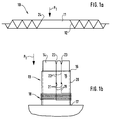
- a centering membrane 10 is shown in a sectional view. This is clear The illustration shows that the centering membrane 10 has an accordion-shaped contour has and centrally has an opening 11. The one immediately surrounding the opening 11 The area of the centering membrane 10 is that which is the first in this application Area 12 is designated. Since here the contour of the centering membrane 10 is accordion-shaped is formed, the first region 12 has an oblique relation to the center line Course.
- a voice coil bobbin 13 is shown, which is tubular.
- This Voice coil former 13 is arranged on a working mandrel 14 which is one of the Voice coil bobbin 13 filled space 15 and at the upper end 16 of the Voice coil former 13 emerges from this.
- the voice coil 18 is attached to the voice coil bobbin 13.
- the two voice coil wires 19, which are connected to the voice coil 18, are on the outer jacket 20 of the voice coil bobbin 13 in the direction of the upper end 16 of the Voice coil carrier 13 guided along and each with a soldering point 21 with the likewise on the outer jacket 20 of the voice coil bobbin 13 along strands 22 conductively connected.
- the contact of the coil wires 19, the soldering points 21 and the strands 22 on the outer jacket 20 of the voice coil bobbin 13 was achieved in that the strands 22nd fixed and tightened in notches 23 arranged at the upper end of the working mandrel 14 were.
- the notches 23 are only mentioned as examples. Rather, the tightening and The strands 22 can also be fixed in another manner known to the person skilled in the art.
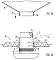
- FIG. 2a If the centering membrane 10 shown in FIG. 1a is pushed onto a voice coil bobbin 13 according to FIG. 1b in the direction of arrow P1 at the upper end 16, conditions are established which are shown in FIG. 2a.
- the voice coil bobbin 13 has been rotated 90 ° clockwise compared to FIG. 1b in FIG. 2a. 2a that the inner edge 24 of the centering membrane 10 bears against the outer jacket 20 of the voice coil bobbin 13 and the first region 12 of the centering membrane 10 opens in the direction of the voice coil 18. It can also be seen from the illustration in FIG.
- the soldering point 21 and the braid 22 lie against the outer jacket 20 of the voice coil bobbin 13, since the braid 22 is fixed and pulled tight in the notch 23 shown.
- the visible soldering point 21 lies between the first area 12 of the centering membrane 10 and the outer jacket 20 of the voice coil bobbin 13.
- the gluing between the voice coil bobbin 13, the centering membrane 10 and the guide point 21 was realized in such a way that in the space 25 between the first area 12 and an adhesive seam 26 was formed on the outer jacket 20 of the voice coil bobbin 13.
- the adhesive seam 26 in one other - not shown - embodiment even before postponing the Centering membrane 10 on the voice coil bobbin 13 or fixing and tightening the strands 22 can be formed on the voice coil former 13. In this case, then the centering membrane 10 pushed into the adhesive seam 26.
- the centering membrane 10 has its end position shown in Fig. 2a on the voice coil former 13 and the adhesive seam 26 is formed, the strands 22 should come out of the notches 23 taken or in another - not shown - embodiment with the respective clamping and fixing arrangement in the direction of arrow P2 arcuate over the top 27 of the centering membrane 10 are guided. Then hardens the adhesive seam 26, get the Strands 22 already have a certain preferred direction with regard to their later attachment points on the speaker basket (everything not shown).
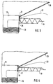
- FIG. 2b shows a membrane 28 which has a neck 29. Is the inside diameter greater / equal to the outer diameter of the voice coil bobbin 13 and the membrane 28 lowered on the voice coil bobbin 13 in the direction of the arrow P3, conditions arise a, which are shown schematically in Fig. 3.
- Fig. 5a can be seen that in an arrangement according to FIG. 3, the strand 22 between the Neck 29 of the membrane 28 and the centering membrane 10 emerges and that the neck 29 and the Centering membrane 10 almost without distance in the longitudinal direction of the voice coil bobbin 13 are arranged to each other.
- FIG. 5b in which the adhesive seam (26) is not shown for reasons of clarity and in which, for the same reasons, a small distance between the voice coil bobbin 13, the centering membrane 10, the soldering points 21, and strand 22 and the neck 29 of the Membrane 28 is realized shows that if all the parts just mentioned are present, the Soldering points 21, the strands 22 and the upper edge 24 of the centering membrane 10 between the Voice coil support 13 and the neck 29 of the membrane 28 are arranged.
- the neck 29 of the membrane 28 is on in FIG. 5d attached to the inside 30 of the voice coil bobbin 13.
- the neck 29 and the adhesive seam 26 refer to the longitudinal direction of the voice coil bobbin 13 are arranged substantially in the same plane.
Landscapes
- Physics & Mathematics (AREA)
- Engineering & Computer Science (AREA)
- Acoustics & Sound (AREA)
- Signal Processing (AREA)
- Audible-Bandwidth Dynamoelectric Transducers Other Than Pickups (AREA)
Applications Claiming Priority (2)
| Application Number | Priority Date | Filing Date | Title |
|---|---|---|---|
| DE19711592 | 1997-03-20 | ||
| DE19711592A DE19711592A1 (de) | 1997-03-20 | 1997-03-20 | Schwingspulenanordnung und Verfahren zu ihrer Herstellung |
Publications (2)
| Publication Number | Publication Date |
|---|---|
| EP0866636A2 true EP0866636A2 (fr) | 1998-09-23 |
| EP0866636A3 EP0866636A3 (fr) | 2004-09-22 |
Family
ID=7823994
Family Applications (1)
| Application Number | Title | Priority Date | Filing Date |
|---|---|---|---|
| EP98104667A Ceased EP0866636A3 (fr) | 1997-03-20 | 1998-03-16 | Bobine mobile et méthode pour sa fabrication |
Country Status (4)
| Country | Link |
|---|---|
| US (1) | US6130955A (fr) |
| EP (1) | EP0866636A3 (fr) |
| JP (1) | JPH1155793A (fr) |
| DE (1) | DE19711592A1 (fr) |
Families Citing this family (5)
| Publication number | Priority date | Publication date | Assignee | Title |
|---|---|---|---|---|
| DE19827793A1 (de) * | 1998-06-23 | 1999-12-30 | Harman Audio Electronic Sys | Schwingspulenanordnung und Verfahren zu ihrer Herstellung |
| JP2001189994A (ja) * | 1999-12-28 | 2001-07-10 | Pioneer Electronic Corp | スピーカ用振動板及び同振動板を備えたスピーカ装置 |
| JP3843939B2 (ja) | 2002-12-03 | 2006-11-08 | 松下電器産業株式会社 | ボイスコイル挿入用治具およびこの治具を用いたスピーカの製造方法およびこの治具を用いて製造されたスピーカ |
| WO2008023420A1 (fr) * | 2006-08-24 | 2008-02-28 | Pioneer Corporation | Unité de haut-parleur |
| US10555085B2 (en) * | 2017-06-16 | 2020-02-04 | Apple Inc. | High aspect ratio moving coil transducer |
Family Cites Families (5)
| Publication number | Priority date | Publication date | Assignee | Title |
|---|---|---|---|---|
| US2007484A (en) * | 1934-04-06 | 1935-07-09 | Magnavox Co | Sound reproducing apparatus |
| NL44190C (fr) * | 1934-12-05 | |||
| US5014323A (en) * | 1989-07-28 | 1991-05-07 | Bose Corporation | Voice coil lead dressing |
| US5249236A (en) * | 1989-12-01 | 1993-09-28 | Kabushiki Kaisha Kenwood | Wiring structure of loudspeaker |
| US5641910A (en) * | 1994-06-13 | 1997-06-24 | Dynamic Instruments, Inc. | Electrodynamic transducer shaker and method for its manufacture |
-
1997
- 1997-03-20 DE DE19711592A patent/DE19711592A1/de not_active Ceased
-
1998
- 1998-03-16 EP EP98104667A patent/EP0866636A3/fr not_active Ceased
- 1998-03-19 US US09/044,650 patent/US6130955A/en not_active Expired - Lifetime
- 1998-03-20 JP JP10072791A patent/JPH1155793A/ja active Pending
Also Published As
| Publication number | Publication date |
|---|---|
| DE19711592A1 (de) | 1998-09-24 |
| US6130955A (en) | 2000-10-10 |
| JPH1155793A (ja) | 1999-02-26 |
| EP0866636A3 (fr) | 2004-09-22 |
Similar Documents
| Publication | Publication Date | Title |
|---|---|---|
| DE3031802C2 (fr) | ||
| DE3221290C2 (fr) | ||
| CH661165A5 (de) | Elektromechanischer wandler mit justierbarem ankerjoch und verfahren zum justieren des ankerjochs. | |
| DE3404975C2 (de) | Stator für einen Elektromotor sowie Verfahren zu dessen Montage | |
| EP0204934A1 (fr) | Bride pour tuyaux | |
| EP0866636A2 (fr) | Bobine mobile et méthode pour sa fabrication | |
| DE10201459B4 (de) | Dämpfungssicke für Lautsprecher und Verfahren zur Herstellung einer Dämpfungssicke für Lautsprecher | |
| DE2512781B2 (de) | Filterkerze mit rueckspuelbare filterapparate | |
| EP1318565B1 (fr) | Antenne, en particuliere antenne de radiotelephonie mobile, avec moyen de centrage pendant la fabrication | |
| DE3403535C2 (fr) | ||
| DE2923901C2 (de) | Geschoßhülle | |
| DE8909435U1 (de) | Anker für einen Elektromotor | |
| DE4419250A1 (de) | Schwingspulenträger für Lautsprecher | |
| EP0967831A2 (fr) | Ensemble bobine mobile et procédé pour sa mise en oeuvre | |
| DE3610086A1 (de) | Endstueck fuer einen elektrischen leiter und verfahren zur herstellung desselben | |
| DE3038905C2 (de) | Lautsprecher und Verfahren zu dessen Herstellung | |
| DE3638693A1 (de) | Kompakter elektro-akustischer uebertrager | |
| DE2451895B2 (de) | Verfahren zur herstellung eines elektromagnetischen relais | |
| DE2855058A1 (de) | Anoden- und kathodenleitungsdrahtaufbau fuer festkoerperelektrolytkondensatoren | |
| DE69225557T2 (de) | Kabelleiter | |
| EP2171730B1 (fr) | Bobine électrique | |
| DE2745183A1 (de) | Elektrodenausbildung der elektronenkanonen einer inline-farbbildroehre | |
| DE3015013A1 (de) | Waermedaemmantel fuer einen rohrbogen | |
| DE2414636A1 (de) | Elektrostatischer wandler | |
| DE1910327C (fr) |
Legal Events
| Date | Code | Title | Description |
|---|---|---|---|
| PUAI | Public reference made under article 153(3) epc to a published international application that has entered the european phase |
Free format text: ORIGINAL CODE: 0009012 |
|
| AK | Designated contracting states |
Kind code of ref document: A2 Designated state(s): AT BE CH DE DK ES FI FR GB GR IE IT LI LU MC NL PT SE |
|
| AX | Request for extension of the european patent |
Free format text: AL;LT;LV;MK;RO;SI |
|
| RAP1 | Party data changed (applicant data changed or rights of an application transferred) |
Owner name: HARMAN AUDIO ELECTRONIC SYSTEMS GMBH |
|
| PUAL | Search report despatched |
Free format text: ORIGINAL CODE: 0009013 |
|
| AK | Designated contracting states |
Kind code of ref document: A3 Designated state(s): AT BE CH DE DK ES FI FR GB GR IE IT LI LU MC NL PT SE |
|
| AX | Request for extension of the european patent |
Extension state: AL LT LV MK RO SI |
|
| 17P | Request for examination filed |
Effective date: 20041013 |
|
| AKX | Designation fees paid |
Designated state(s): AT BE CH DE DK ES FI FR GB GR IE IT LI LU MC NL PT SE |
|
| 17Q | First examination report despatched |
Effective date: 20050701 |
|
| STAA | Information on the status of an ep patent application or granted ep patent |
Free format text: STATUS: THE APPLICATION HAS BEEN REFUSED |
|
| 18R | Application refused |
Effective date: 20050902 |