EP0866642A2 - Elektrischer Heizeinheit und Herstellungsverfahren - Google Patents
Elektrischer Heizeinheit und Herstellungsverfahren Download PDFInfo
- Publication number
- EP0866642A2 EP0866642A2 EP98301796A EP98301796A EP0866642A2 EP 0866642 A2 EP0866642 A2 EP 0866642A2 EP 98301796 A EP98301796 A EP 98301796A EP 98301796 A EP98301796 A EP 98301796A EP 0866642 A2 EP0866642 A2 EP 0866642A2
- Authority
- EP
- European Patent Office
- Prior art keywords
- base
- peripheral wall
- insulation material
- press tool
- dish
- Prior art date
- Legal status (The legal status is an assumption and is not a legal conclusion. Google has not performed a legal analysis and makes no representation as to the accuracy of the status listed.)
- Granted
Links
Images



Classifications
-
- H—ELECTRICITY
- H05—ELECTRIC TECHNIQUES NOT OTHERWISE PROVIDED FOR
- H05B—ELECTRIC HEATING; ELECTRIC LIGHT SOURCES NOT OTHERWISE PROVIDED FOR; CIRCUIT ARRANGEMENTS FOR ELECTRIC LIGHT SOURCES, IN GENERAL
- H05B3/00—Ohmic-resistance heating
- H05B3/68—Heating arrangements specially adapted for cooking plates or analogous hot-plates
- H05B3/74—Non-metallic plates, e.g. vitroceramic, ceramic or glassceramic hobs, also including power or control circuits
- H05B3/748—Resistive heating elements, i.e. heating elements exposed to the air, e.g. coil wire heater
-
- H—ELECTRICITY
- H05—ELECTRIC TECHNIQUES NOT OTHERWISE PROVIDED FOR
- H05B—ELECTRIC HEATING; ELECTRIC LIGHT SOURCES NOT OTHERWISE PROVIDED FOR; CIRCUIT ARRANGEMENTS FOR ELECTRIC LIGHT SOURCES, IN GENERAL
- H05B2203/00—Aspects relating to Ohmic resistive heating covered by group H05B3/00
- H05B2203/017—Manufacturing methods or apparatus for heaters
-
- Y—GENERAL TAGGING OF NEW TECHNOLOGICAL DEVELOPMENTS; GENERAL TAGGING OF CROSS-SECTIONAL TECHNOLOGIES SPANNING OVER SEVERAL SECTIONS OF THE IPC; TECHNICAL SUBJECTS COVERED BY FORMER USPC CROSS-REFERENCE ART COLLECTIONS [XRACs] AND DIGESTS
- Y10—TECHNICAL SUBJECTS COVERED BY FORMER USPC
- Y10T—TECHNICAL SUBJECTS COVERED BY FORMER US CLASSIFICATION
- Y10T29/00—Metal working
- Y10T29/49—Method of mechanical manufacture
- Y10T29/49002—Electrical device making
- Y10T29/49082—Resistor making
- Y10T29/49083—Heater type
-
- Y—GENERAL TAGGING OF NEW TECHNOLOGICAL DEVELOPMENTS; GENERAL TAGGING OF CROSS-SECTIONAL TECHNOLOGIES SPANNING OVER SEVERAL SECTIONS OF THE IPC; TECHNICAL SUBJECTS COVERED BY FORMER USPC CROSS-REFERENCE ART COLLECTIONS [XRACs] AND DIGESTS
- Y10—TECHNICAL SUBJECTS COVERED BY FORMER USPC
- Y10T—TECHNICAL SUBJECTS COVERED BY FORMER US CLASSIFICATION
- Y10T29/00—Metal working
- Y10T29/49—Method of mechanical manufacture
- Y10T29/49002—Electrical device making
- Y10T29/49117—Conductor or circuit manufacturing
- Y10T29/49124—On flat or curved insulated base, e.g., printed circuit, etc.
- Y10T29/49128—Assembling formed circuit to base
-
- Y—GENERAL TAGGING OF NEW TECHNOLOGICAL DEVELOPMENTS; GENERAL TAGGING OF CROSS-SECTIONAL TECHNOLOGIES SPANNING OVER SEVERAL SECTIONS OF THE IPC; TECHNICAL SUBJECTS COVERED BY FORMER USPC CROSS-REFERENCE ART COLLECTIONS [XRACs] AND DIGESTS
- Y10—TECHNICAL SUBJECTS COVERED BY FORMER USPC
- Y10T—TECHNICAL SUBJECTS COVERED BY FORMER US CLASSIFICATION
- Y10T29/00—Metal working
- Y10T29/49—Method of mechanical manufacture
- Y10T29/49002—Electrical device making
- Y10T29/49117—Conductor or circuit manufacturing
- Y10T29/49124—On flat or curved insulated base, e.g., printed circuit, etc.
- Y10T29/49155—Manufacturing circuit on or in base
- Y10T29/49158—Manufacturing circuit on or in base with molding of insulated base
Definitions
- This invention relates to an electric heater unit, particularly but not exclusively for use in glass-ceramic cooking appliances, and a method for manufacture thereof.
- Heaters for use in glass-ceramic surface electric cooking equipment are well known, having an insulation material in the shape of a bowl comprising a base and peripheral wall, the base supporting, or having adjacent thereto, one or more heating conductors in the form of an electrical resistance material formed as a wire coil, a ribbon, a halogen infra red tube or other means.
- the electrical and thermal insulation material is a critical component. At least a part of the base insulation may be a high performance insulation which is a compacted microporous material.
- microporous' is used herein to identify porous or cellular materials in which the ultimate size of the cells or voids is less than the mean free path of an air molecule at NTP, i.e. of the order of 100 nm or smaller.
- a material which is microporous in this sense will exhibit very low transfer of heat by air conduction (that is, due to collisions between air molecules).
- microporous materials include aerogel, which is a gel in which the liquid phase has been replaced by a gaseous phase in such a way as to avoid the shrinkage which would occur if the gel were dried directly from a liquid.
- aerogel which is a gel in which the liquid phase has been replaced by a gaseous phase in such a way as to avoid the shrinkage which would occur if the gel were dried directly from a liquid.
- a substantially identical structure can be obtained by controlled precipitation from solution, the temperature and pH being controlled during precipitation to obtain an open lattice precipitate.
- a binder may be added to provide increased strength, in which case a heat treatment may be necessary in order to cure the binder.
- a known form of high performance microporous thermal insulation material comprises microporous silica particles compacted to consolidate the material into a handleable form, and typically includes ceramic fibre or glass filament reinforcement and rutile powder opacifier.
- the microporous insulation may be directly in contact with the heating conductor, acting as a support for the conductor.
- the conductor may be supported by a lesser thermal insulation material which has mechanical properties quite different from the microporous thermal insulation.
- the base support and peripheral wall may be formed as one piece with the wall and base being a homogeneous material.
- the base is a microporous insulation it has been found to be advantageous to have the peripheral wall made from a separate stronger material. Heaters have been made which have wall and base support formed as pressed microporous insulation material but the walls were mechanically weak and a stronger material was fitted to the top of the peripheral wall to improve handle ability.
- Another design idea uses a microporous base support with a separate wall component also made from microporous insulation. It is claimed that the separate wall component can be made with high mechanical strength and good insulation properties. The higher strength is achieved by a special hardening process. This solution is costly. The wall component is slow to produce and needs care in handling.
- an electric heater unit comprising a supporting dish having therein a base of compacted microporous insulation material, at least one electrical resistance heating element supported on, or adjacent to, the base, and a peripheral wall of compacted microporous insulation material, wherein the peripheral wall is integral with the base and is of controlled compaction density.
- an electric heater unit comprising the steps of providing a supporting dish, forming in the supporting dish a base by compacting powdered microporous insulation material therein, and providing at least one electrical resistance heating element supported on or adjacent to the base, wherein the method includes the additional step of forming in the supporting dish a peripheral wall integral with the base by compacting further microporous insulation material into the dish to a controlled compaction density.
- the compaction density of the peripheral wall may be different from that of the base.
- the peripheral wall may be of higher compaction density than the base.
- a press tool having separable central and surrounding peripheral portions, powdered microporous insulation material is compacted into the supporting dish with the press tool to form the base and, optionally, part of the peripheral wall, the peripheral portion of the press tool is retracted to form a cavity into which further powdered microporous insulation material is introduced, the peripheral portion of the press tool is advanced to compact the further powdered microporous insulation material to a controlled compaction density to form the peripheral wall integral with the base, and the central and peripheral portions of the press tool are retracted from the dish.
- powdered microporous insulation material is compacted into the supporting dish with a press tool to form the base and, optionally, part of the peripheral wall, the press tool and the dish are then separated and a further press tool having separable central and surrounding peripheral portions is provided, at least one electrical resistance heating element is supported at a face of the central portion of the press tool and is pressed by the press tool into the surface of the base of compacted microporous insulation material in the supporting dish for partial embedding therein, the peripheral portion of the further press tool is retracted to form a cavity into which further powdered microporous insulation material is introduced, the peripheral portion of the further press tool is advanced to compact the further powdered microporous insulation material to a controlled compaction density to form the peripheral wall integral with the base, and the central and peripheral portions of the further press tool are retracted from the dish, leaving the heating element securely partially embedded in the base.
- the powdered microporous insulation material and/or the further powdered microporous insulation material may be introduced into the press tool by way of a tube through a wall thereof.
- the powdered material may be pumped through the tube such as by using high pressure gas induction or by using a vane pump, a diaphragm pump or a peristaltic pump.
- the supporting dish may be circular and the press tool with separable central and surrounding peripheral portions may have a circular central portion and an annular surrounding peripheral portion.
- the further powdered microporous insulation material may have a composition substantially the same as, or different from, that of the material forming the base.
- the peripheral wall of compacted microporous insulation material preferably is under internal compressive strain after provision in the supporting dish.
- the peripheral wall is suitably arranged to have a top surface capable of contacting the underside of a glass-ceramic cook top of a cooking appliance, in particular the peripheral wall may have a height at least as great as the height of side walls of the supporting dish.
- Such top surface may be profiled such that it is higher at its centre than at its edges.
- the peripheral wall and/or the base may include reinforcing glass filaments.
- Such filaments may, for example, be selected from E glass, R glass, S glass and silica.
- the supporting dish may comprise a metal.
- the at least one electrical resistance heating element may, for example, comprise coiled wire or coiled ribbon, or plane or corrugated ribbon disposed flat or edgewise, on or adjacent to the base in the supporting dish.
- a peripheral wall of microporous insulation material is provided in which the composition and the compaction density thereof are the same as or different from a base of microporous insulation material with which it is integrally provided.
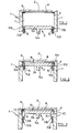
- a press for use in manufacturing an electric heater unit comprises a housing 1, a cover 2 and a press tool 3 which is slidable inside the housing 1.
- the end of the housing 1 is recessed to receive the rim of a metal dish 4 which will form the supporting dish for the electric heater unit.
- the press tool 3 is of circular shape and comprises a circular central portion 3A and an annular surrounding peripheral portion 3B.
- the central portion 3A and annular portion 3B are separable from one another and are slidable in the housing by means of plungers 5A and 5B.
- the central portion 3A has an extended cylindrical wall 6 able to slidably interface with the annular portion 3B.
- the insulation material may have the following composition:
- the powdered material may be introduced into the space 7 before the dish 4 and cover 2 are installed. Alternatively it may be pumped into the space 7 by way of a tube T passing through the wall of the housing 1. Pumping of the powder through the tube T may be by using high pressure gas induction or using a vane pump, a diaphragm pump, or a peristaltic pump.
- the press is operated, for example hydraulically, to urge both portions 3A and 3B of the press tool simultaneously towards the dish 4, by means of the plungers 5A and 5B, as shown in Figure 2, thereby compacting the insulation material into the dish 4 to form a base 8 in the dish.
- holes 9 are provided through the press tool 3 to further facilitate air displacement.
- the compacted insulation material forming the base 8 may be formed with a step 8A at the edge thereof, by forming a complementary step in the press tool 3.
- Such step 8A forms a base portion of a peripheral wall of insulation material which is to be provided in the dish as hereinafter described.
- the next step in the process is to retract the annular portion 3B of the press tool, by means of the plungers 5B while leaving the central portion 3A of the press tool in contact with the surface of the base 8 of insulation material. Further powdered microporous insulation material is then pumped through the tube T into the space 10 vacated by the annular portion 3B of the press tool.
- the annular portion 3B of the press tool is then advanced towards the dish 4 to compact the further insulation material to form a peripheral wall 11 of microporous insulation material integrally moulded with the base 8 of microporous insulation material.
- the wall 11 is arranged to be compacted to a higher compaction density than that on average of the base 8.
- the base 8 may have a compaction density of about 300 kg/m 3 whereas the wall 11 may be compacted to a density of about 350 kg/m 3 .
- the wall 11 may have a composition the same as, or different from, that of the base 8.
- An example of a particular composition for the wall is:
- Both portions 3A, 3B of the press tool are then retracted as shown in Figure 5, the cover 2 is removed and the dish 4 with the base 8 and peripheral wall 11 therein is extracted.
- the dish 4 with the base 8 and peripheral wall 11 therein is shown in Figure 6.
- the peripheral wall 11 has a height corresponding at least to the height of side walls of the dish 4, and preferably extending somewhat above the side walls of the dish 4.
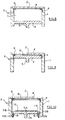
- an electrical resistance heating element 12 is provided supported on the base 8 of microporous thermal insulation material as shown in Figure 7.
- Heating element 12 may comprise any of the well known forms, such as coiled wire or ribbon or a corrugated ribbon supported edgewise and partly embedded in the base 8.
- Such a corrugated ribbon form of element is shown in Figure 7 and also in Figure 16, which represents a plan view of the heater of Figure 7 and in which there is additionally provided a well known form of temperature limiter 13.
- the heater of Figures 7 and 16 is intended for operation in a glass-ceramic top cooking appliance (not shown) where it is secured beneath a glass-ceramic cook top (not shown) with the upper surface 11A of the peripheral wall in contact with the underside of the glass-ceramic top.
- the top surface of the peripheral wall 11 may be profiled such that it is higher at its centre than at its edges. This is achieved by providing a complementary profile on the inner face 14A of the annular portion 3B of the press tool ( Figure 5).
- FIGS 8 to 15 illustrate an alternative process sequence including the moulding of corrugated ribbon heating element 12 into base 8 of microporous insulation material.
- a press is provided, as in Figure 1, comprising a housing 1 recessed to receive the rim of a metal dish 4 forming the supporting dish of an electric heater unit.
- a cover 2 is provided for the housing.
- a circular press tool 3 is provided, slidable in the housing 1 by means of a plunger 5.
- a predetermined quantity of powdered microporous thermal insulation material is introduced into the space 7 between the press tool 3 and the dish 4 using either of the methods as previously described with reference to Figure 1.
- the press is operated to urge the press tool 3 towards the dish 4, as shown in Figure 9, thereby compacting the insulation material into the dish 4 to form a base 8 in the dish.
- the press tool 3 is then withdrawn from the housing and replaced by the press tool shown in Figure 10, which is of two part form as previously described with reference to Figure 1, having a central circular portion 3A operated by a plunger 5A and an annular peripheral portion 3B operated by plungers 5B.
- the top surface 15 of the central portion 3A of the press tool is provided with a pattern of grooves to partially receive therein a corrugated ribbon heating element 12.
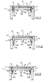
- the press tool 3A, 3B is advanced by means of plungers 5A, 5B towards the base 8 of compacted insulation material, as shown in Figure 11, to cause the heating element 12 to be partially embedded in the surface of the base 8. It may be advantageous if, during the initial provision of the base 8, as described with reference to Figures 8 and 9, the microporous insulation material of the base 8 is compacted to less than its required final density. This facilitates embedding of the heating element 12 therein and subsequent to such embedding, the base 8 is compacted to its desired final density by pressure exerted thereon by the surface of the press tool 3A, 3B.
- the annular portion 3B of the press tool is then advanced towards the dish 4 to compact the further insulation material to form a peripheral wall 11 of microporous insulation material integrally moulded with the base 8 of microporous insulation material.
- the wall 11 is arranged to be compacted to a higher compaction density than that on average of the base 8.
- the wall 11 may have a composition the same as, or different from, that of the base 8.
- Both portions 3A, 3B of the press tool are then retracted as shown in Figure 14, leaving the heating element 12 securely partially embedded in the base 8. It is preferred that the central portion 3A of the press tool is retracted before the annular portion 3B to minimise risk of damage to material of the wall 11.
- the cover 2 is removed from the press and the heater unit comprising the dish 4, with the base 8, peripheral wall 11 and heating element 12, extracted. Such heater unit is shown in section in Figure 15 and, after the addition of a temperature limiter 13, in plan view in Figure 16.
Landscapes
- Chemical & Material Sciences (AREA)
- Engineering & Computer Science (AREA)
- Ceramic Engineering (AREA)
- Resistance Heating (AREA)
- Heating, Cooling, Or Curing Plastics Or The Like In General (AREA)
- Moulds For Moulding Plastics Or The Like (AREA)
- Surface Heating Bodies (AREA)
- Thermal Insulation (AREA)
Applications Claiming Priority (2)
| Application Number | Priority Date | Filing Date | Title |
|---|---|---|---|
| GB9705923A GB2323507B (en) | 1997-03-21 | 1997-03-21 | Electric heater unit and method of manufacture |
| GB9705923 | 1997-03-21 |
Publications (3)
| Publication Number | Publication Date |
|---|---|
| EP0866642A2 true EP0866642A2 (de) | 1998-09-23 |
| EP0866642A3 EP0866642A3 (de) | 1999-01-27 |
| EP0866642B1 EP0866642B1 (de) | 2006-08-02 |
Family
ID=10809658
Family Applications (1)
| Application Number | Title | Priority Date | Filing Date |
|---|---|---|---|
| EP98301796A Expired - Lifetime EP0866642B1 (de) | 1997-03-21 | 1998-03-11 | Elektrische Heizeinheit und Herstellungsverfahren |
Country Status (7)
| Country | Link |
|---|---|
| US (1) | US6205648B1 (de) |
| EP (1) | EP0866642B1 (de) |
| JP (1) | JPH10270156A (de) |
| AT (1) | ATE335384T1 (de) |
| DE (1) | DE69835389T2 (de) |
| ES (1) | ES2270495T3 (de) |
| GB (1) | GB2323507B (de) |
Cited By (2)
| Publication number | Priority date | Publication date | Assignee | Title |
|---|---|---|---|---|
| EP1049357A3 (de) * | 1999-04-30 | 2001-12-12 | Diehl AKO Stiftung & Co. KG | Aufnahmeschale mit einer Isolierschicht für Strahlungsheizelemente und Verfahren zur Herstellung von Kanälen in der Isolierschicht |
| WO2002071802A1 (de) * | 2001-03-06 | 2002-09-12 | Schott Glas | Keramik-kochfeld |
Families Citing this family (1)
| Publication number | Priority date | Publication date | Assignee | Title |
|---|---|---|---|---|
| US8753447B2 (en) * | 2009-06-10 | 2014-06-17 | Novellus Systems, Inc. | Heat shield for heater in semiconductor processing apparatus |
Family Cites Families (8)
| Publication number | Priority date | Publication date | Assignee | Title |
|---|---|---|---|---|
| US3612829A (en) * | 1970-07-17 | 1971-10-12 | Gen Motors Corp | Ceramic top infrared cooking assembly |
| DE3020326C2 (de) | 1980-05-29 | 1985-12-19 | Grünzweig + Hartmann und Glasfaser AG, 6700 Ludwigshafen | Strahlungsheizkörper mit einer elektrischen Heizwendel, insbesondere für eine Glaskeramik-Kochplatte |
| NZ197851A (en) * | 1980-08-13 | 1984-09-28 | Micropore International Ltd | Cooker element:temperature sensor receives heated air |
| GB8526235D0 (en) * | 1985-10-24 | 1985-11-27 | Glynwed Tubes & Fittings | Electrofusion coupler |
| GB2250669B (en) * | 1988-05-27 | 1992-08-19 | Ceramaspeed Ltd | Radiant electric heaters |
| GB2275162B (en) * | 1993-02-11 | 1996-04-10 | Ceramaspeed Ltd | Radiant electric heater method |
| GB2275160B (en) * | 1993-02-11 | 1996-04-03 | Ceramaspeed Ltd | Method of manufacturing a radiant electric heater |
| GB2278261B (en) * | 1993-05-21 | 1996-07-03 | Ceramaspeed Ltd | Method of manufacturing a radiant electric heater |
-
1997
- 1997-03-21 GB GB9705923A patent/GB2323507B/en not_active Expired - Fee Related
-
1998
- 1998-03-03 US US09/033,791 patent/US6205648B1/en not_active Expired - Lifetime
- 1998-03-11 DE DE69835389T patent/DE69835389T2/de not_active Expired - Fee Related
- 1998-03-11 AT AT98301796T patent/ATE335384T1/de not_active IP Right Cessation
- 1998-03-11 ES ES98301796T patent/ES2270495T3/es not_active Expired - Lifetime
- 1998-03-11 EP EP98301796A patent/EP0866642B1/de not_active Expired - Lifetime
- 1998-03-19 JP JP10090762A patent/JPH10270156A/ja not_active Withdrawn
Cited By (3)
| Publication number | Priority date | Publication date | Assignee | Title |
|---|---|---|---|---|
| EP1049357A3 (de) * | 1999-04-30 | 2001-12-12 | Diehl AKO Stiftung & Co. KG | Aufnahmeschale mit einer Isolierschicht für Strahlungsheizelemente und Verfahren zur Herstellung von Kanälen in der Isolierschicht |
| WO2002071802A1 (de) * | 2001-03-06 | 2002-09-12 | Schott Glas | Keramik-kochfeld |
| US6921882B2 (en) | 2001-03-06 | 2005-07-26 | Schott Ag | Ceramic cooktop |
Also Published As
| Publication number | Publication date |
|---|---|
| EP0866642A3 (de) | 1999-01-27 |
| JPH10270156A (ja) | 1998-10-09 |
| GB2323507B (en) | 2000-11-29 |
| GB9705923D0 (en) | 1997-05-07 |
| DE69835389T2 (de) | 2007-08-09 |
| US6205648B1 (en) | 2001-03-27 |
| ATE335384T1 (de) | 2006-08-15 |
| ES2270495T3 (es) | 2007-04-01 |
| GB2323507A (en) | 1998-09-23 |
| DE69835389D1 (de) | 2006-09-14 |
| EP0866642B1 (de) | 2006-08-02 |
Similar Documents
| Publication | Publication Date | Title |
|---|---|---|
| US4203197A (en) | Method for making a ceramic bond heater | |
| DE3262043D1 (en) | Radiant electric heating element and method of manufacturing the same | |
| US5477605A (en) | Method of manufacturing a radiant electric heater | |
| CA1093133A (en) | Electrical cooker unit for a glass ceramic plate type electrical cooker | |
| US5512731A (en) | Radiant electric heater | |
| US6205648B1 (en) | Electric heater unit and method of manufacture | |
| EP0625866B1 (de) | Strahlungsheizkörper | |
| JPS6235487A (ja) | 電気ラジアント加熱装置およびその製造方法並びに製造装置 | |
| US5369874A (en) | Method of manufacturing a radiant electric heater | |
| US5048176A (en) | Method of making a radiant heater | |
| JP3500583B2 (ja) | 放射電熱器の製造方法 | |
| CA1100560A (en) | Ceramic band heater and method for making the same | |
| US20020113058A1 (en) | Base for an electric heater and method of manufacture | |
| US20060027562A1 (en) | Radiant heater for a cooker, with a moulded insulating base | |
| CN222393334U (zh) | 一种陶瓷天线用陶瓷烧结炉 | |
| JPH0714798Y2 (ja) | 高温高圧プレス機のプレス用部材 | |
| EP1375446A1 (de) | Thermisches Isolationsmaterial | |
| JPS6136162A (ja) | 導電性セラミツク複合体 | |
| CN2131266Y (zh) | 一种电绝缘珠 | |
| WO2023234892A1 (en) | Radiant heater | |
| JP2903131B2 (ja) | 電熱ヒータおよびその製造方法 | |
| EP0903962A2 (de) | Herstellungsverfahren für eine Elektrische Heizanordnung | |
| CN109322464A (zh) | 蓄热瓷砖、蓄热瓷砖制造工艺及电加热设备 | |
| JPH01241787A (ja) | セラミックヒータの製造方法 | |
| KR19990061400A (ko) | 영구자석 제조장치 |
Legal Events
| Date | Code | Title | Description |
|---|---|---|---|
| PUAI | Public reference made under article 153(3) epc to a published international application that has entered the european phase |
Free format text: ORIGINAL CODE: 0009012 |
|
| AK | Designated contracting states |
Kind code of ref document: A2 Designated state(s): AT BE CH DE DK ES FR GB GR IT LI NL PT SE |
|
| PUAL | Search report despatched |
Free format text: ORIGINAL CODE: 0009013 |
|
| AK | Designated contracting states |
Kind code of ref document: A3 Designated state(s): AT BE CH DE DK ES FI FR GB GR IE IT LI LU MC NL PT SE |
|
| 17P | Request for examination filed |
Effective date: 19990225 |
|
| AKX | Designation fees paid |
Free format text: AT BE CH DE DK ES FR GB GR IT LI NL PT SE |
|
| GRAP | Despatch of communication of intention to grant a patent |
Free format text: ORIGINAL CODE: EPIDOSNIGR1 |
|
| GRAS | Grant fee paid |
Free format text: ORIGINAL CODE: EPIDOSNIGR3 |
|
| GRAA | (expected) grant |
Free format text: ORIGINAL CODE: 0009210 |
|
| AK | Designated contracting states |
Kind code of ref document: B1 Designated state(s): AT BE CH DE DK ES FR GR IT LI NL PT SE |
|
| PG25 | Lapsed in a contracting state [announced via postgrant information from national office to epo] |
Ref country code: NL Free format text: LAPSE BECAUSE OF FAILURE TO SUBMIT A TRANSLATION OF THE DESCRIPTION OR TO PAY THE FEE WITHIN THE PRESCRIBED TIME-LIMIT Effective date: 20060802 Ref country code: LI Free format text: LAPSE BECAUSE OF FAILURE TO SUBMIT A TRANSLATION OF THE DESCRIPTION OR TO PAY THE FEE WITHIN THE PRESCRIBED TIME-LIMIT Effective date: 20060802 Ref country code: IT Free format text: LAPSE BECAUSE OF FAILURE TO SUBMIT A TRANSLATION OF THE DESCRIPTION OR TO PAY THE FEE WITHIN THE PRESCRIBED TIME-LIMIT;WARNING: LAPSES OF ITALIAN PATENTS WITH EFFECTIVE DATE BEFORE 2007 MAY HAVE OCCURRED AT ANY TIME BEFORE 2007. THE CORRECT EFFECTIVE DATE MAY BE DIFFERENT FROM THE ONE RECORDED. Effective date: 20060802 Ref country code: CH Free format text: LAPSE BECAUSE OF FAILURE TO SUBMIT A TRANSLATION OF THE DESCRIPTION OR TO PAY THE FEE WITHIN THE PRESCRIBED TIME-LIMIT Effective date: 20060802 Ref country code: BE Free format text: LAPSE BECAUSE OF FAILURE TO SUBMIT A TRANSLATION OF THE DESCRIPTION OR TO PAY THE FEE WITHIN THE PRESCRIBED TIME-LIMIT Effective date: 20060802 Ref country code: AT Free format text: LAPSE BECAUSE OF FAILURE TO SUBMIT A TRANSLATION OF THE DESCRIPTION OR TO PAY THE FEE WITHIN THE PRESCRIBED TIME-LIMIT Effective date: 20060802 |
|
| REG | Reference to a national code |
Ref country code: CH Ref legal event code: EP |
|
| REF | Corresponds to: |
Ref document number: 69835389 Country of ref document: DE Date of ref document: 20060914 Kind code of ref document: P |
|
| PG25 | Lapsed in a contracting state [announced via postgrant information from national office to epo] |
Ref country code: SE Free format text: LAPSE BECAUSE OF FAILURE TO SUBMIT A TRANSLATION OF THE DESCRIPTION OR TO PAY THE FEE WITHIN THE PRESCRIBED TIME-LIMIT Effective date: 20061102 Ref country code: DK Free format text: LAPSE BECAUSE OF FAILURE TO SUBMIT A TRANSLATION OF THE DESCRIPTION OR TO PAY THE FEE WITHIN THE PRESCRIBED TIME-LIMIT Effective date: 20061102 |
|
| NLV1 | Nl: lapsed or annulled due to failure to fulfill the requirements of art. 29p and 29m of the patents act | ||
| PG25 | Lapsed in a contracting state [announced via postgrant information from national office to epo] |
Ref country code: PT Free format text: LAPSE BECAUSE OF FAILURE TO SUBMIT A TRANSLATION OF THE DESCRIPTION OR TO PAY THE FEE WITHIN THE PRESCRIBED TIME-LIMIT Effective date: 20070102 |
|
| ET | Fr: translation filed | ||
| REG | Reference to a national code |
Ref country code: CH Ref legal event code: PL |
|
| REG | Reference to a national code |
Ref country code: ES Ref legal event code: FG2A Ref document number: 2270495 Country of ref document: ES Kind code of ref document: T3 |
|
| PLBE | No opposition filed within time limit |
Free format text: ORIGINAL CODE: 0009261 |
|
| STAA | Information on the status of an ep patent application or granted ep patent |
Free format text: STATUS: NO OPPOSITION FILED WITHIN TIME LIMIT |
|
| 26N | No opposition filed |
Effective date: 20070503 |
|
| PG25 | Lapsed in a contracting state [announced via postgrant information from national office to epo] |
Ref country code: GR Free format text: LAPSE BECAUSE OF FAILURE TO SUBMIT A TRANSLATION OF THE DESCRIPTION OR TO PAY THE FEE WITHIN THE PRESCRIBED TIME-LIMIT Effective date: 20061103 |
|
| PGFP | Annual fee paid to national office [announced via postgrant information from national office to epo] |
Ref country code: FR Payment date: 20070326 Year of fee payment: 10 Ref country code: ES Payment date: 20080207 Year of fee payment: 11 |
|
| PGFP | Annual fee paid to national office [announced via postgrant information from national office to epo] |
Ref country code: DE Payment date: 20080312 Year of fee payment: 11 |
|
| REG | Reference to a national code |
Ref country code: FR Ref legal event code: ST Effective date: 20091130 |
|
| PG25 | Lapsed in a contracting state [announced via postgrant information from national office to epo] |
Ref country code: DE Free format text: LAPSE BECAUSE OF NON-PAYMENT OF DUE FEES Effective date: 20091001 |
|
| PG25 | Lapsed in a contracting state [announced via postgrant information from national office to epo] |
Ref country code: FR Free format text: LAPSE BECAUSE OF NON-PAYMENT OF DUE FEES Effective date: 20091123 |
|
| REG | Reference to a national code |
Ref country code: ES Ref legal event code: FD2A Effective date: 20090312 |
|
| PG25 | Lapsed in a contracting state [announced via postgrant information from national office to epo] |
Ref country code: ES Free format text: LAPSE BECAUSE OF NON-PAYMENT OF DUE FEES Effective date: 20090312 |
|
| PG25 | Lapsed in a contracting state [announced via postgrant information from national office to epo] |
Ref country code: FR Free format text: LAPSE BECAUSE OF NON-PAYMENT OF DUE FEES Effective date: 20090331 |