EP0866643A2 - Four à micro-ondes - Google Patents
Four à micro-ondes Download PDFInfo
- Publication number
- EP0866643A2 EP0866643A2 EP97307296A EP97307296A EP0866643A2 EP 0866643 A2 EP0866643 A2 EP 0866643A2 EP 97307296 A EP97307296 A EP 97307296A EP 97307296 A EP97307296 A EP 97307296A EP 0866643 A2 EP0866643 A2 EP 0866643A2
- Authority
- EP
- European Patent Office
- Prior art keywords
- microwave oven
- fan housing
- outlet
- filter
- air
- Prior art date
- Legal status (The legal status is an assumption and is not a legal conclusion. Google has not performed a legal analysis and makes no representation as to the accuracy of the status listed.)
- Granted
Links
Images

Classifications
-
- F—MECHANICAL ENGINEERING; LIGHTING; HEATING; WEAPONS; BLASTING
- F24—HEATING; RANGES; VENTILATING
- F24C—DOMESTIC STOVES OR RANGES ; DETAILS OF DOMESTIC STOVES OR RANGES, OF GENERAL APPLICATION
- F24C7/00—Stoves or ranges heated by electric energy
- F24C7/02—Stoves or ranges heated by electric energy using microwaves
-
- H—ELECTRICITY
- H05—ELECTRIC TECHNIQUES NOT OTHERWISE PROVIDED FOR
- H05B—ELECTRIC HEATING; ELECTRIC LIGHT SOURCES NOT OTHERWISE PROVIDED FOR; CIRCUIT ARRANGEMENTS FOR ELECTRIC LIGHT SOURCES, IN GENERAL
- H05B6/00—Heating by electric, magnetic or electromagnetic fields
- H05B6/64—Heating using microwaves
- H05B6/642—Cooling of the microwave components and related air circulation systems
Definitions
- the present invention relates to a fan housing configured for incorporation during assembly into a microwave oven having an outlet through which air is directed.
- a microwave oven is an appliance that utilizes microwave energy to cook food.
- a microwave oven is mounted to a wall above a gas or electric hob of a conventional stove and incorporates a ventilator for filtering cooking odours.
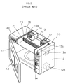
- a conventional microwave oven is illustrated in Figure 4 and includes a main body 10 defining a cooking chamber 11 and an electrical component compartment 12.
- the front of the cooking chamber 11 has a door 13 is hingedly mounted to one side of the main body 10 to enable the cooking chamber to be opened and closed.
- the electrical component compartment 12 contains a magnetron 12a for generating microwave energy and for directing it into the cooking chamber 11, and a high-voltage transformer 12b for providing a high voltage to the magnetron 12a.
- a control panel 14 on the front of the electrical component compartment 12 enables the cooking operation to be controlled.
- An air vent 40 is formed in the bottom of the main body 10 beneath the cooking chamber 11 to allow for the inflow of odour, smoke, etc. from foodstuffs being cooked on the hob beneath the microwave oven.
- the air entering the vent 40 is filtered and is directed back into the room.
- a conventional ventilator is illustrated in Figure 5 and comprises an upper duct 18 located in an upper portion of the main body 10 for guiding air that is introduced via the air vents 40 back outside.
- the front of the upper duct 18 is provided with a grill 20.
- a pair of duct cases 15, each having an air intake 15a and an air outlet 15b, are mounted towards the rear of the upper duct 18 and a fan 16 is installed within each of them.
- An electric motor 17 is positioned between the duct cases 15 and is connected to the fans 16.
- the upper duct 18 also includes a filter 19 vertically supported on each side by a pair of rails to filter air before it passes through the grill 20.
- the high voltage transformer 12b energizes the magnetron 12a which emits microwave energy to direct it into the cooking chamber 1 to cook food in the cooking chamber 11.
- the ventilator operates to suck odour, smoke, etc. created by the food being cooked on the hob beneath the microwave in through the air vent 40 formed on the bottom of the main body 10, and through right and left paths (not illustrated) of the main body 10.
- the air is passed through the filter 19 via the outlets 15b of the duct cases 15 and is filtered thereby before being reintroduced back into the room through the grill 20.
- a problem with the conventional microwave oven filter described above is that it must be of a sufficient size to extend across the whole of the air duct 18 to ensure that all the air passing through the duct case 15 is filtered before being reintroduced into the room, even though a filter of such a large size is not required.
- the increase in size of the filter disadvantageously increases the manufacturing cost of the microwave oven and decreases its efficiency.
- a fan housing according to the present invention is characterised in that a filter is directly mounted to the fan housing over the outlet.
- the filter is co-extensive with the outlet.
- the filter is removeably mounted.
- the or each filter is located between two pairs of elongate protrusions, each pair being formed on the fan housing on opposite sides of the outlet.
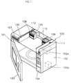
- FIG. 1 A cut-away perspective view of a microwave oven is illustrated in Figure 1 and includes a main body 100 defining a cooking chamber 101, and an electrical component compartment 102.
- a door 103 is hingedly mounted to the front of the cooking chamber 101 to enable it to be opened and closed.
- the electrical component compartment 102 contains a magnetron 102a for producing microwave energy and for directing it into the cooking chamber 101, and a high voltage transformer 102b for applying high voltage to the magnetron 102.
- a control panel 104 is mounted on the front of the electrical component compartment 102 to enable the microwave oven to be controlled.
- the microwave oven also has a ventilator for filtering odour, smoke, etc. generated by the cooking process by a hob, disposed beneath the microwave oven, and for filtering air circulating around a kitchen or room.
- the ventilator includes an upper duct 120 mounted on an upper part of the cooking chamber 101, a path (not illustrated) on both sides of the main body 100 for guiding the outside air flowing through the main body 100, and a grill 107 installed at the front of the upper duct 120 for venting air to the outside.
- the ventilator includes a pair of duct cases 110 each having an intake 111 and an outlet 112 in the rear of the upper duct 120.
- a fan 105 is housed in each of the duct cases 110 for providing a flow of air, and a motor 106 is interposed between the duct cases 110 for rotating the fans 105 simultaneously.
- the upper duct 120 has filters 108 for filtering air before air is vented to the room through the grill 107.
- the filters 108 are directly mounted to the outlets 112 formed on the front of the duct cases 110, and are of the same size as each of the outlets 112.
- a pair of rails 113 are each formed at upper and lower portions of the respective outlets 112 and the filters 108 are inserted between them and are retained in position thereby. That is, both upper and lower edges of the filters 108 are inserted between the rails 113 in a manner that the filters 108 are fixed to the outlet 112.
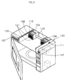
- FIG. 3 A perspective view of a filter assembly for a microwave oven in accordance with a second preferred embodiment of the present invention is illustrated in Figure 3. Similar reference numerals denote similar reference parts throughout the preferred embodiments of the present invention.
- This embodiment is identical to the embodiment described above except that the whole of the front of the duct cases provide the outlets 112 and the filters are correspondingly larger to cover the outlets 112.
- the filters of the preferred embodiments are each directly mounted to the front of the outlets of the respective duct cases, and may be of the same size as that of the respective outlets of the duct cases. This results in a reduction in the size of the filters thus lowering the overall production costs.
Landscapes
- Physics & Mathematics (AREA)
- Electromagnetism (AREA)
- Engineering & Computer Science (AREA)
- Chemical & Material Sciences (AREA)
- Combustion & Propulsion (AREA)
- Mechanical Engineering (AREA)
- General Engineering & Computer Science (AREA)
- Electric Ovens (AREA)
- Constitution Of High-Frequency Heating (AREA)
Applications Claiming Priority (2)
| Application Number | Priority Date | Filing Date | Title |
|---|---|---|---|
| KR9710015 | 1997-03-22 | ||
| KR1019970010015A KR100229138B1 (ko) | 1997-03-22 | 1997-03-22 | 전자렌지의 필터장치 |
Publications (3)
| Publication Number | Publication Date |
|---|---|
| EP0866643A2 true EP0866643A2 (fr) | 1998-09-23 |
| EP0866643A3 EP0866643A3 (fr) | 1999-02-03 |
| EP0866643B1 EP0866643B1 (fr) | 2002-03-27 |
Family
ID=19500544
Family Applications (1)
| Application Number | Title | Priority Date | Filing Date |
|---|---|---|---|
| EP97307296A Expired - Lifetime EP0866643B1 (fr) | 1997-03-22 | 1997-09-19 | Four à micro-ondes |
Country Status (7)
| Country | Link |
|---|---|
| US (1) | US5886330A (fr) |
| EP (1) | EP0866643B1 (fr) |
| JP (1) | JP3342821B2 (fr) |
| KR (1) | KR100229138B1 (fr) |
| CN (1) | CN1102219C (fr) |
| DE (1) | DE69711361T2 (fr) |
| MY (1) | MY116152A (fr) |
Cited By (4)
| Publication number | Priority date | Publication date | Assignee | Title |
|---|---|---|---|---|
| EP1220573A2 (fr) | 2000-12-30 | 2002-07-03 | Lg Electronics Inc. | Structure d'un ensemble moteur ventilé dans un four à micro-ondes |
| EP1220577A3 (fr) * | 2000-12-30 | 2003-05-28 | Lg Electronics Inc. | Four à micro-ondes équipé d'un évacuateur d'air |
| EP1220575A3 (fr) * | 2000-12-30 | 2004-03-03 | Lg Electronics Inc. | Structure de ventilation dans un four à micro-ondes et la structure d'accueil d'une lampe associée |
| EP1217875A3 (fr) * | 2000-12-20 | 2004-07-14 | Lg Electronics Inc. | Bâti d'un four à micro-ondes |
Families Citing this family (19)
| Publication number | Priority date | Publication date | Assignee | Title |
|---|---|---|---|---|
| GB2341677B (en) * | 1999-11-20 | 2000-12-27 | Merrychef Ltd | Ovens with catalytic converters |
| US6191389B1 (en) | 2000-03-31 | 2001-02-20 | General Electric Company | Grease resistant oven grille |
| JP2003083547A (ja) * | 2001-09-11 | 2003-03-19 | Matsushita Electric Ind Co Ltd | 高周波加熱装置 |
| KR100848161B1 (ko) * | 2002-11-29 | 2008-07-23 | 삼성전자주식회사 | 공기정화장치를 구비한 조리기 |
| CN100343585C (zh) * | 2003-04-25 | 2007-10-17 | 乐金电子(天津)电器有限公司 | 微波炉的排气结构 |
| US20070138171A1 (en) * | 2003-10-16 | 2007-06-21 | Lee Dong H | Microwave oven and an upper duct structure thereof |
| KR100609174B1 (ko) * | 2003-10-16 | 2006-08-02 | 엘지전자 주식회사 | 전자레인지의 베이스 플레이트 구조 |
| KR100582306B1 (ko) * | 2003-11-05 | 2006-05-22 | 엘지전자 주식회사 | 카세트 타잎 후드 겸용 전자 레인지 |
| KR100609156B1 (ko) * | 2004-02-26 | 2006-08-02 | 엘지전자 주식회사 | 후드겸용 전자레인지 |
| US7019272B2 (en) * | 2004-07-01 | 2006-03-28 | Whirlpool Corporation | Wall mounted microwave oven having an exhaust ventilation system |
| US7193195B2 (en) * | 2004-07-01 | 2007-03-20 | Whirlpool Corporation | Wall mounted microwave oven having a top vent with filter system |
| NZ539220A (en) * | 2005-04-05 | 2008-01-31 | Gavin Paul Lee | Computer dust filter (pixicap) |
| US8375849B2 (en) | 2009-09-01 | 2013-02-19 | Manitowoc Foodservice Companies, Llc | Method and apparatus for an air inlet in a cooking device |
| WO2011028724A1 (fr) * | 2009-09-01 | 2011-03-10 | Manitowoc Foodservice Companies, Llc. | Procédé et appareil pour ventiler un dispositif de cuisson |
| US20160205728A1 (en) * | 2015-01-13 | 2016-07-14 | General Electric Company | Microwave appliances |
| US9742171B2 (en) | 2015-05-04 | 2017-08-22 | Midwest Innovative Products, Llc | Electrical cord connection covering techniques |
| CN106969391A (zh) * | 2017-05-17 | 2017-07-21 | 广东美的厨房电器制造有限公司 | 烹饪装置 |
| US11285421B2 (en) | 2018-04-12 | 2022-03-29 | Electrolux Home Products, Inc. | Filter media for filtration of cooking fumes |
| CN115235016A (zh) * | 2022-06-16 | 2022-10-25 | 青岛海尔空调器有限总公司 | 空气处理装置和空气炸锅联动的电器设备及其控制方法 |
Family Cites Families (10)
| Publication number | Priority date | Publication date | Assignee | Title |
|---|---|---|---|---|
| US3654417A (en) * | 1970-10-30 | 1972-04-04 | Litton Precision Prod Inc | Microwave oven including air flow system |
| US3952640A (en) * | 1973-03-01 | 1976-04-27 | Vent-Cair, Inc. | Apparatus and method for extracting grease and smoke, and method of installing the same |
| US3859901A (en) * | 1974-02-25 | 1975-01-14 | Gen Electric | Recirculating ventilating hood |
| DE2631352C3 (de) * | 1976-07-13 | 1983-02-17 | Bayer Ag, 5090 Leverkusen | Verfahren zur partikelarmen Sterilisation |
| US4072487A (en) * | 1976-12-10 | 1978-02-07 | Steiger Tractor Inc. | Air conditioning apparatus for tractor cab |
| US4143646A (en) * | 1977-10-27 | 1979-03-13 | Home Metal Products Company A Division Of Mobex Corporation | Cooking apparatus and exhaust system |
| US4418261A (en) * | 1982-01-15 | 1983-11-29 | Amana Refrigeration, Inc. | Microwave oven and ventilator system |
| DE3484603D1 (de) * | 1983-12-16 | 1991-06-20 | Nitta Co | Luftreiniger. |
| JPH03164640A (ja) * | 1989-11-21 | 1991-07-16 | Yamaha Corp | レンジフード |
| DE4143124A1 (de) * | 1990-12-28 | 1992-07-16 | Oejelid Goeran Dipl Ing | Elektrisches hausgeraet |
-
1997
- 1997-03-22 KR KR1019970010015A patent/KR100229138B1/ko not_active Expired - Fee Related
- 1997-09-19 DE DE69711361T patent/DE69711361T2/de not_active Expired - Fee Related
- 1997-09-19 EP EP97307296A patent/EP0866643B1/fr not_active Expired - Lifetime
- 1997-09-26 US US08/935,084 patent/US5886330A/en not_active Expired - Fee Related
- 1997-09-29 MY MYPI97004536A patent/MY116152A/en unknown
- 1997-10-07 JP JP27484997A patent/JP3342821B2/ja not_active Expired - Fee Related
- 1997-10-13 CN CN97120076A patent/CN1102219C/zh not_active Expired - Fee Related
Cited By (5)
| Publication number | Priority date | Publication date | Assignee | Title |
|---|---|---|---|---|
| EP1217875A3 (fr) * | 2000-12-20 | 2004-07-14 | Lg Electronics Inc. | Bâti d'un four à micro-ondes |
| EP1220573A2 (fr) | 2000-12-30 | 2002-07-03 | Lg Electronics Inc. | Structure d'un ensemble moteur ventilé dans un four à micro-ondes |
| EP1220577A3 (fr) * | 2000-12-30 | 2003-05-28 | Lg Electronics Inc. | Four à micro-ondes équipé d'un évacuateur d'air |
| EP1220575A3 (fr) * | 2000-12-30 | 2004-03-03 | Lg Electronics Inc. | Structure de ventilation dans un four à micro-ondes et la structure d'accueil d'une lampe associée |
| EP1220573A3 (fr) * | 2000-12-30 | 2004-08-04 | Lg Electronics Inc. | Structure d'un ensemble moteur ventilé dans un four à micro-ondes |
Also Published As
| Publication number | Publication date |
|---|---|
| EP0866643A3 (fr) | 1999-02-03 |
| DE69711361T2 (de) | 2002-11-21 |
| JPH10267291A (ja) | 1998-10-09 |
| CN1102219C (zh) | 2003-02-26 |
| DE69711361D1 (de) | 2002-05-02 |
| JP3342821B2 (ja) | 2002-11-11 |
| KR100229138B1 (ko) | 1999-11-01 |
| KR19980074278A (ko) | 1998-11-05 |
| EP0866643B1 (fr) | 2002-03-27 |
| CN1194354A (zh) | 1998-09-30 |
| US5886330A (en) | 1999-03-23 |
| MY116152A (en) | 2003-11-28 |
Similar Documents
| Publication | Publication Date | Title |
|---|---|---|
| EP0866643B1 (fr) | Four à micro-ondes | |
| US4786774A (en) | Combination compact microwave oven and ventilator system | |
| CA1142600A (fr) | Four a micro-onde avec ventilateur d'extraction, et methode de montage connexe a l'implantation | |
| EP0751698B1 (fr) | Four à micro-ondes et à convection | |
| US7193195B2 (en) | Wall mounted microwave oven having a top vent with filter system | |
| US7482562B2 (en) | Microwave range configured both to heat food and to exhaust contaminated air generated by a cooking appliance provided therebeneath | |
| KR100565222B1 (ko) | 후드겸용 전자레인지의 배기 안내장치 | |
| JP4021831B2 (ja) | 電子レンジ | |
| US7482563B2 (en) | Microwave range configured both to heat food and to exhaust contaminated air generated by a cooking appliance provided therebeneath | |
| US20240015859A1 (en) | Cooking device | |
| US7671310B2 (en) | Microwave range having hood | |
| US7019272B2 (en) | Wall mounted microwave oven having an exhaust ventilation system | |
| KR100938205B1 (ko) | 오븐 | |
| EP1424877A2 (fr) | Four à micro-ondes monté sur un mur | |
| US3334621A (en) | Range forced venting discharge system | |
| CA1133071A (fr) | Systeme d'aeration pour four a micro-ondes et event d'extraction combines | |
| KR100747815B1 (ko) | 전기오븐의 배기필터 장착구조 | |
| KR19980058169U (ko) | 후드겸용 전자렌지 | |
| US20240060652A1 (en) | Cooking equipment | |
| KR102848838B1 (ko) | 조리 기기 | |
| KR100551489B1 (ko) | 벽걸이형 전자렌지 | |
| KR20110018224A (ko) | 후드겸용 전자레인지 | |
| EP0224775A1 (fr) | Four à micro-ondes encastrable | |
| KR20250027088A (ko) | 배기장치 및 이를 구비하는 조리기기 | |
| CA1227251A (fr) | Ensemble compact de four a micro-ondes et dispositif d'aeration |
Legal Events
| Date | Code | Title | Description |
|---|---|---|---|
| PUAI | Public reference made under article 153(3) epc to a published international application that has entered the european phase |
Free format text: ORIGINAL CODE: 0009012 |
|
| AK | Designated contracting states |
Kind code of ref document: A2 Designated state(s): DE FR GB |
|
| PUAL | Search report despatched |
Free format text: ORIGINAL CODE: 0009013 |
|
| AK | Designated contracting states |
Kind code of ref document: A3 Designated state(s): AT BE CH DE DK ES FI FR GB GR IE IT LI LU MC NL PT SE |
|
| 17P | Request for examination filed |
Effective date: 19990311 |
|
| AKX | Designation fees paid |
Free format text: DE FR GB |
|
| 17Q | First examination report despatched |
Effective date: 20001124 |
|
| GRAG | Despatch of communication of intention to grant |
Free format text: ORIGINAL CODE: EPIDOS AGRA |
|
| GRAG | Despatch of communication of intention to grant |
Free format text: ORIGINAL CODE: EPIDOS AGRA |
|
| GRAH | Despatch of communication of intention to grant a patent |
Free format text: ORIGINAL CODE: EPIDOS IGRA |
|
| GRAH | Despatch of communication of intention to grant a patent |
Free format text: ORIGINAL CODE: EPIDOS IGRA |
|
| REG | Reference to a national code |
Ref country code: GB Ref legal event code: IF02 |
|
| GRAA | (expected) grant |
Free format text: ORIGINAL CODE: 0009210 |
|
| AK | Designated contracting states |
Kind code of ref document: B1 Designated state(s): DE FR GB |
|
| REF | Corresponds to: |
Ref document number: 69711361 Country of ref document: DE Date of ref document: 20020502 |
|
| ET | Fr: translation filed | ||
| PLBE | No opposition filed within time limit |
Free format text: ORIGINAL CODE: 0009261 |
|
| STAA | Information on the status of an ep patent application or granted ep patent |
Free format text: STATUS: NO OPPOSITION FILED WITHIN TIME LIMIT |
|
| 26N | No opposition filed |
Effective date: 20021230 |
|
| PGFP | Annual fee paid to national office [announced via postgrant information from national office to epo] |
Ref country code: FR Payment date: 20040908 Year of fee payment: 8 |
|
| PGFP | Annual fee paid to national office [announced via postgrant information from national office to epo] |
Ref country code: GB Payment date: 20040915 Year of fee payment: 8 |
|
| PGFP | Annual fee paid to national office [announced via postgrant information from national office to epo] |
Ref country code: DE Payment date: 20040916 Year of fee payment: 8 |
|
| PG25 | Lapsed in a contracting state [announced via postgrant information from national office to epo] |
Ref country code: GB Free format text: LAPSE BECAUSE OF NON-PAYMENT OF DUE FEES Effective date: 20050919 |
|
| PG25 | Lapsed in a contracting state [announced via postgrant information from national office to epo] |
Ref country code: DE Free format text: LAPSE BECAUSE OF NON-PAYMENT OF DUE FEES Effective date: 20060401 |
|
| GBPC | Gb: european patent ceased through non-payment of renewal fee |
Effective date: 20050919 |
|
| PG25 | Lapsed in a contracting state [announced via postgrant information from national office to epo] |
Ref country code: FR Free format text: LAPSE BECAUSE OF NON-PAYMENT OF DUE FEES Effective date: 20060531 |
|
| REG | Reference to a national code |
Ref country code: FR Ref legal event code: ST Effective date: 20060531 |