EP0867202A2 - Zumischeinrichtung für Feuerlöschanlagen - Google Patents
Zumischeinrichtung für Feuerlöschanlagen Download PDFInfo
- Publication number
- EP0867202A2 EP0867202A2 EP98105713A EP98105713A EP0867202A2 EP 0867202 A2 EP0867202 A2 EP 0867202A2 EP 98105713 A EP98105713 A EP 98105713A EP 98105713 A EP98105713 A EP 98105713A EP 0867202 A2 EP0867202 A2 EP 0867202A2
- Authority
- EP
- European Patent Office
- Prior art keywords
- foam
- mixing device
- flow
- additive
- pump
- Prior art date
- Legal status (The legal status is an assumption and is not a legal conclusion. Google has not performed a legal analysis and makes no representation as to the accuracy of the status listed.)
- Withdrawn
Links
- 238000009434 installation Methods 0.000 title 1
- XLYOFNOQVPJJNP-UHFFFAOYSA-N water Substances O XLYOFNOQVPJJNP-UHFFFAOYSA-N 0.000 claims abstract description 27
- 239000000654 additive Substances 0.000 claims abstract description 20
- 230000000996 additive effect Effects 0.000 claims abstract description 19
- 239000006260 foam Substances 0.000 claims description 37
- 239000003795 chemical substances by application Substances 0.000 claims description 28
- 238000012544 monitoring process Methods 0.000 abstract 1
- 239000004088 foaming agent Substances 0.000 description 4
- 239000012141 concentrate Substances 0.000 description 3
- 230000001419 dependent effect Effects 0.000 description 2
- 238000005259 measurement Methods 0.000 description 2
- 238000010276 construction Methods 0.000 description 1
- 238000010586 diagram Methods 0.000 description 1
- 238000011010 flushing procedure Methods 0.000 description 1
- 239000000203 mixture Substances 0.000 description 1
- 238000010079 rubber tapping Methods 0.000 description 1
Images
Classifications
-
- A—HUMAN NECESSITIES
- A62—LIFE-SAVING; FIRE-FIGHTING
- A62C—FIRE-FIGHTING
- A62C5/00—Making of fire-extinguishing materials immediately before use
- A62C5/02—Making of fire-extinguishing materials immediately before use of foam
Definitions
- the invention relates to an admixing device for Fire extinguishing systems for adding a foam or film-forming Additive to a fire water flow, according to the generic features of claim 1.
- Such an electronically controlled mixing device for Fire trucks are known from DE-OS 30 38 334.
- a volumetric admixture pump with speed-controlled Drive device provided to a measuring and Control device connected in the form of a microprocessor is.
- the required additive flow rate will be based on a measurement signal from a flow meter in the Extinguishing water pipe calculated and the corresponding speed of the Additive pump set.
- This admixture or Dosing device is according to the pump characteristic of volumetric additive pump a desired additive volume flow assigned a speed.
- the admixture of the foam or film-forming additive or foam concentrate to the extinguishing water flow is primarily from the proportionality not given under all operating conditions dependent on the admixing characteristic.
- the volumetric additive pump must be highly precise be made to the proportionality with different To be able to maintain the delivery pressure.
- the additive line second flow meter serves however only for checking the amount of admixture, whereby its actual value is only reported to a display device. From the two Actual values of the water or additive flow rate then the actual value of the mixing ratio is displayed. Unless thus from the desired setpoints of the mixing ratio If there are deviations, this must be adjusted manually will.
- it is only in a relatively small flow range the required accuracy exists and also requires one constant readjustment by the operator, which however in Extinguishing mission is hardly feasible, especially not at stationary, unattended extinguishing systems or Sprinkler systems.
- the invention is based on the object automatic mixing device for fire extinguishing systems create that with very high accuracy in one particular wide flow range can be used.
- the current one Extinguishing water flow from a magnetic-inductive Flow meter is detected via an analog-to-digital converter to a central control unit with a computer or Microcontroller transmit the resulting amount of foam or additives calculated to ensure compliance with the digitally preset on a selector switch Mixing ratio is required.
- the central one Control unit with the computer or microcontroller regulates due to digital signal processing in fractions of a second via an assigned digital-to-analog converter Electric motor for driving the additive pump with precise speeds and thus the downstream self-priming Foam agent pump to promote the necessary Amount of foaming agent.
- This foam agent pump can be relative be simply constructed, in particular, an expensive, volumetric additive pump can be dispensed with.
- the amount of foam concentrate concentrate thus delivered will be preferred immediately with an extremely short dead time over one arranged immediately after the foam agent pump, electronic flow meter detected and via an analog-to-digital converter with the set percentage on Selector switch compared. This is due to the digital Signal processing several times per second so that the speed of the Electric motor and the associated foam agent pump is constantly adjusted so that the Microcontroller or the central control unit calculated Amount (setpoint) of foam agent in the extinguishing line or Extinguishing water flow is introduced.
- the achievable metering accuracy of this admixing device is therefore in the range of +/- 0.2%.
- This mixing accuracy takes place even with a water flow of 1/100 of the maximum water flow absolutely accurate, e.g. in the area from a minimum of 10 l / min to a maximum of 1000 l / min.
- Preferred embodiments of the proposed Mixing devices are the subject of the dependent claims.
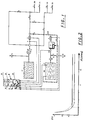
- Fig. 1 is a water pump 1 for that from a water tank 17th suctioned extinguishing water shown.
- the water tank 17 can also be an external supply 15, for example, from a hydrant. It can also this external supply 15 for flushing the entire extinguishing system be used.
- a foam agent pump 2 is shown, with a Foam medium tank 18 is connected.
- the foam agent pump 2 is installed via a gear, e.g. one Timing belt from a speed-controlled drive motor 2 ' driven, as described in more detail below. Furthermore are usual in the pipe or hose network of the extinguishing system Valves 30, 31 and 32 are provided, for example the Foam center line through external supply from a point 14, e.g. additional foam agent container to make or around the Foam agent tank 18 to fill and / or rinse.
- a gear e.g. one Timing belt from a speed-controlled drive motor 2 ' driven, as described in more detail below.
- Valves 30, 31 and 32 are provided, for example the Foam center line through external supply from a point 14, e.g. additional foam agent container to make or around the Foam agent tank 18 to fill and / or rinse.
- a re-suction button 11 is provided for example, after changing the container To activate foam agent from additional containers.
- a selector switch 12 is provided with which for fast Processing by the computer 19 in digital values Desired or often precisely prescribed by the manufacturer Mixing ratio is set.
- the display is as Accessory preferably an LCD display 13 is provided on the the respectively activated tapping points 20, 21, 22, 23 of the Extinguishing water can be displayed.
- a characteristic curve of a is preferably shown in FIG. 2 as an example Flow meter 3 and 4 used magnetic-inductive Tube sensor shown, the electrical conductivity of the Extinguishing water flowing through or the foaming agent used, in a perpendicular to the flow direction Magnetic field to induce an electrical voltage.
- the Linearity range with an error guise of well under 1% above do not leave an extremely large flow range.
- the Output signals of the flow meters 3 and 4 are each via an analog-digital converter directly coupled to the computer 19 9a (only one shown here) and possibly each digitized an input amplifier as actual values.
- the computer 19 is then in a split second, e.g. 15x each Second taking into account that of the selector switch 12 the control deviation is calculated using the digitally specified setpoint and as an output variable of the central control part 9 via a Digital-to-analog converter 9b driven by the drive motor 2 ', e.g. by frequency control or pulse width modulation, depending on used engine type.
- a Digital-to-analog converter 9b driven by the drive motor 2 ', e.g. by frequency control or pulse width modulation, depending on used engine type.
- Flow rates up to approx. 1000 l / min are usually a 24 V DC motor used while stationary a 230V / 400V three-phase motor with a frequency converter Suitability for all flow ranges used as drive motor 2 ' becomes.
- the control part 9 can also the regulation of the power supply of the magnetic field coils to the Flow meters 3 and 4 take over.
- the flow meter 4 for the foaming agent is for Achieve a compact design and cable routing if possible close downstream of the preferred as a self-priming Screw pump designed foam agent pump 2 arranged. This is in connection with the digital Signal processing in the central control unit 9 or the Computer 19 a highly dynamic control behavior regardless of Foam agent supply pressure reached, because of the Flow meter 4 an immediate feedback on the Pump output takes place. So the amount of foaming agent conveyed e.g. increased several times within a second or be reduced or the entire flow range be traversed in a positive or negative direction.
Landscapes
- Health & Medical Sciences (AREA)
- Public Health (AREA)
- Business, Economics & Management (AREA)
- Emergency Management (AREA)
- Fire-Extinguishing By Fire Departments, And Fire-Extinguishing Equipment And Control Thereof (AREA)
- Fire-Extinguishing Compositions (AREA)
- Accessories For Mixers (AREA)
Abstract
Description
- Fig. 1
- ein Schaltungsschema einer automatischen, elektronisch geregelten Zumischeinrichtung; und
- Fig. 2
- eine Darstellung einer Kennlinie eines bevorzugt verwendeten Durchflußmeßgerätes.
Claims (9)
- Zumischeinrichtung für Feuerlöschanlagen zum Zumischen eines schaum- oder filmbildenden Zusatzmittels zu einem Löschwasserstrom, mit einer Zusatzmittelleitung, die an eine Löschwasserleitung angeschlossen ist und endseitig zu mindestens einer Abgabestelle (20, 21, 22, 23) führt,
dadurch gekennzeichnet, daß
in der Löschwasserleitung und der Zusatzmittelleitung jeweils ein Durchflußmeßgerät (3, 4) angeordnet ist, die mit einer zentralen Steuereinheit (9) gekoppelt sind, die zur Errechnung der erforderlichen Menge an Zusatzmittel unter Berücksichtigung des an einem Wahlschalter (12) digital eingestellten Sollwertes einen Rechner (19) aufweist, der mit einem Antriebsmotor (2') einer Schaummittelpumpe (2) gekoppelt ist. - Zumischeinrichtung nach Anspruch 1, dadurch gekennzeichnet, daß beide Durchflußmeßgeräte (3, 4) als magnetisch-induktiv messende Rohrsensoren ausgebildet sind.
- Zumischeinrichtung nach Anspruch 1 oder 2, dadurch gekennzeichnet, daS die Schaummittelpumpe (2) als selbstansaugende Schraubenspindelpumpe ausgebildet ist.
- Zumischeinrichtung nach einem der Ansprüche 1 bis 3, dadurch gekennzeichnet, daS zur Ansteuerung des Antriebsmotors (2') der Schaummittelpumpe (2) ein Digital-Analog-Wandler (9b) vorgesehen ist.
- Zumischeinrichtung nach einem der Ansprüche 1 bis 4, dadurch gekennzeichnet, daß in der Löschwasserleitung und/oder der Schaummittelleitung Meßfühler (7, 8) angeordnet sind, die an die zentrale Steuereinheit (9) angeschlossen sind.
- Zumischeinrichtung nach einem der Ansprüche 1 bis 5, dadurch gekennzeichnet, daß an einem Schaummitteltank (18) ein Füllstandsmelder (5) angeordnet ist, der mit der zentralen Steuereinheit (9) in Verbindung steht.
- Zumischeinrichtung nach einem der Ansprüche 1 bis 6, dadurch gekennzeichnet, daß bei fehlendem Durchfluß-bzw. Füllstands-Signal von den Meßfühlern (5, 7, 8) die Schaummittelpumpe (2) vom der zentralen Steuereinheit (9) aus automatisch abschaltbar ist.
- Zumischeinrichtung nach einem der Ansprüche 1 bis 7, dadurch gekennzeichnet, daß das Schaummittel-Durchflußmeßgerät (4) in unmittelbarer Nähe zur Schaummittelpumpe (2) angeordnet ist.
- Zumischeinrichtung nach einem der Ansprüche 1 bis 8, dadurch gekennzeichnet, daß beide Durchflußmeßgeräte (3, 4) jeweils über einen hochauflösenden Analog-Digital-Wandler (9a) an den Rechner (19) angeschlossen sind.
Applications Claiming Priority (2)
| Application Number | Priority Date | Filing Date | Title |
|---|---|---|---|
| DE29705611U | 1997-03-29 | ||
| DE29705611U DE29705611U1 (de) | 1997-03-29 | 1997-03-29 | Zumischeinrichtung für Feuerlöschanlagen |
Publications (2)
| Publication Number | Publication Date |
|---|---|
| EP0867202A2 true EP0867202A2 (de) | 1998-09-30 |
| EP0867202A3 EP0867202A3 (de) | 1999-12-22 |
Family
ID=8038165
Family Applications (1)
| Application Number | Title | Priority Date | Filing Date |
|---|---|---|---|
| EP98105713A Withdrawn EP0867202A3 (de) | 1997-03-29 | 1998-03-29 | Zumischeinrichtung für Feuerlöschanlagen |
Country Status (2)
| Country | Link |
|---|---|
| EP (1) | EP0867202A3 (de) |
| DE (1) | DE29705611U1 (de) |
Cited By (3)
| Publication number | Priority date | Publication date | Assignee | Title |
|---|---|---|---|---|
| EP1095673A2 (de) | 1999-10-25 | 2001-05-02 | Lenzing Technik GmbH & CO. KG | Zumischeinrichtung für Feuerlöschanlagen |
| WO2004041726A1 (en) * | 2002-11-04 | 2004-05-21 | Arch Chemicals, Inc | Method of water treatment |
| US7197037B2 (en) | 2002-10-25 | 2007-03-27 | Alpine Electronics, Inc. | Device and system for message processing |
Families Citing this family (1)
| Publication number | Priority date | Publication date | Assignee | Title |
|---|---|---|---|---|
| WO2006081625A1 (en) * | 2005-02-04 | 2006-08-10 | Cft Services Pty Ltd | Fire protection induction system |
Citations (2)
| Publication number | Priority date | Publication date | Assignee | Title |
|---|---|---|---|---|
| DE3038334A1 (de) | 1980-10-10 | 1982-10-21 | Albert Ziegler Gmbh & Co Kg, 7928 Giengen | Einrichtung fuer feuerloeschfahrzeuge zum zumischen eines schaum- oder filmbildenden zusatzmittels zum loeschwasserstroms |
| DE3726672A1 (de) | 1986-10-09 | 1988-04-14 | Total Feuerschutz Gmbh | Einrichtung fuer feuerloeschfahrzeuge mit einem automatischen, elektronisch gesteuerten zumischer |
Family Cites Families (2)
| Publication number | Priority date | Publication date | Assignee | Title |
|---|---|---|---|---|
| US3040758A (en) * | 1958-07-21 | 1962-06-26 | Pyrene Co Ltd | Inductors for liquids |
| US4324294A (en) * | 1979-02-07 | 1982-04-13 | John McLoughlin | Chemical injection control system for fire fighting |
-
1997
- 1997-03-29 DE DE29705611U patent/DE29705611U1/de not_active Expired - Lifetime
-
1998
- 1998-03-29 EP EP98105713A patent/EP0867202A3/de not_active Withdrawn
Patent Citations (2)
| Publication number | Priority date | Publication date | Assignee | Title |
|---|---|---|---|---|
| DE3038334A1 (de) | 1980-10-10 | 1982-10-21 | Albert Ziegler Gmbh & Co Kg, 7928 Giengen | Einrichtung fuer feuerloeschfahrzeuge zum zumischen eines schaum- oder filmbildenden zusatzmittels zum loeschwasserstroms |
| DE3726672A1 (de) | 1986-10-09 | 1988-04-14 | Total Feuerschutz Gmbh | Einrichtung fuer feuerloeschfahrzeuge mit einem automatischen, elektronisch gesteuerten zumischer |
Cited By (5)
| Publication number | Priority date | Publication date | Assignee | Title |
|---|---|---|---|---|
| EP1095673A2 (de) | 1999-10-25 | 2001-05-02 | Lenzing Technik GmbH & CO. KG | Zumischeinrichtung für Feuerlöschanlagen |
| US7197037B2 (en) | 2002-10-25 | 2007-03-27 | Alpine Electronics, Inc. | Device and system for message processing |
| WO2004041726A1 (en) * | 2002-11-04 | 2004-05-21 | Arch Chemicals, Inc | Method of water treatment |
| US7094353B2 (en) | 2002-11-04 | 2006-08-22 | Arch Chemicals, Inc. | Method of water treatment |
| US7575673B2 (en) | 2002-11-04 | 2009-08-18 | Arch Chemicals, Inc. | Method of water treatment |
Also Published As
| Publication number | Publication date |
|---|---|
| EP0867202A3 (de) | 1999-12-22 |
| DE29705611U1 (de) | 1997-07-03 |
Similar Documents
| Publication | Publication Date | Title |
|---|---|---|
| DE3050169C2 (de) | Verfahren und Vorrichtung zur Konstanthaltung der Viskosität eines kontinuierlich strömenden Flüssigkeitsgemisches | |
| EP0733232B1 (de) | Einrichtung zum dosieren von fluiden sowie getränkeausschankanlage mit einer solchen dosiereinrichtung | |
| DE69519165T2 (de) | Vorrichtung zum abgeben von flüssigkeiten im gewünschten mengenverhältnis | |
| DE3038334C2 (de) | ||
| DE602004009343T2 (de) | Dosiersystem zur dosierung eines flüssigzusatzes in eine druckwasserleitung | |
| WO1996023936A1 (de) | Regelvorrichtung für eine wasserversorgungsanlage | |
| DE3726672C2 (de) | ||
| EP0356440A1 (de) | Anordnung zur durchflussmessung | |
| EP0867202A2 (de) | Zumischeinrichtung für Feuerlöschanlagen | |
| EP0895960A1 (de) | Verfahren und Anlage zur Abgabe von Flüssigkeit aus einem mehrere Kammern enthaltenden Tankwagen | |
| EP1123163B1 (de) | Verfahren und vorrichtung zum dosieren und mischen unterschiedlicher komponenten | |
| DE3817852C1 (de) | ||
| DE2847431A1 (de) | Dosiervorrichtung | |
| DE10324076A1 (de) | Fördereinrichtung für eine Lackieranlage | |
| DE3413726C2 (de) | ||
| DE4413249A1 (de) | Verfahren zum Aufspritzen von aus Farbmengen zusammengesetzten Farbmischungen auf Unterlagen, insbesondere von aus mehreren Komponenten zusammengesetzten Farben, und Gerät zur Durchführung des Verfahrens | |
| DE3536992C1 (de) | Vorrichtung zum Mischen von Fluessigkeiten | |
| EP0230860A1 (de) | Dosier-Regelanornung und Dosier-Verfahren, insbesondere für ein Feuerwehr-Löschfahrzeug | |
| DE2738531C2 (de) | Vorrichtung zum Eindosieren einer Zusatzflüssigkeit in eine Hauptflüssigkeit | |
| DE2556245C2 (de) | Zumischvorrichtung für ein Schaumlöschgerät | |
| DE2644931A1 (de) | Mess- und kontrolleinrichtung bei zweikomponenten-dosieranlagen | |
| DE4002777A1 (de) | Wassermengensteuerung an einer maschine zur verarbeitung von moerteln | |
| DE10320147A1 (de) | Verfahren und Versorgungssystem zur dosierten Materialversorgung einer Beschichtungsvorrichtung | |
| EP0179189A2 (de) | Verfahren und Vorrichtung zur Dosierung und Mischung zweier Fluidkomponenten | |
| DE9404549U1 (de) | Schaumlöschanlage |
Legal Events
| Date | Code | Title | Description |
|---|---|---|---|
| PUAI | Public reference made under article 153(3) epc to a published international application that has entered the european phase |
Free format text: ORIGINAL CODE: 0009012 |
|
| AK | Designated contracting states |
Kind code of ref document: A2 Designated state(s): AT CH DE FR GB LI |
|
| AX | Request for extension of the european patent |
Free format text: AL;LT;LV;MK;RO;SI |
|
| PUAL | Search report despatched |
Free format text: ORIGINAL CODE: 0009013 |
|
| AK | Designated contracting states |
Kind code of ref document: A3 Designated state(s): AT BE CH DE DK ES FI FR GB GR IE IT LI LU MC NL PT SE |
|
| AX | Request for extension of the european patent |
Free format text: AL;LT;LV;MK;RO;SI |
|
| 17P | Request for examination filed |
Effective date: 19991220 |
|
| AKX | Designation fees paid |
Free format text: AT CH DE FR GB LI |
|
| 17Q | First examination report despatched |
Effective date: 20040115 |
|
| STAA | Information on the status of an ep patent application or granted ep patent |
Free format text: STATUS: THE APPLICATION IS DEEMED TO BE WITHDRAWN |
|
| 18D | Application deemed to be withdrawn |
Effective date: 20051001 |