EP0867286B1 - Tintenstrahldrucker und Tintenstrahldruckverfahren - Google Patents
Tintenstrahldrucker und Tintenstrahldruckverfahren Download PDFInfo
- Publication number
- EP0867286B1 EP0867286B1 EP98302294A EP98302294A EP0867286B1 EP 0867286 B1 EP0867286 B1 EP 0867286B1 EP 98302294 A EP98302294 A EP 98302294A EP 98302294 A EP98302294 A EP 98302294A EP 0867286 B1 EP0867286 B1 EP 0867286B1
- Authority
- EP
- European Patent Office
- Prior art keywords
- ink
- heating element
- pulse
- chamber
- print cartridge
- Prior art date
- Legal status (The legal status is an assumption and is not a legal conclusion. Google has not performed a legal analysis and makes no representation as to the accuracy of the status listed.)
- Expired - Lifetime
Links
Images


Classifications
-
- B—PERFORMING OPERATIONS; TRANSPORTING
- B41—PRINTING; LINING MACHINES; TYPEWRITERS; STAMPS
- B41J—TYPEWRITERS; SELECTIVE PRINTING MECHANISMS, i.e. MECHANISMS PRINTING OTHERWISE THAN FROM A FORME; CORRECTION OF TYPOGRAPHICAL ERRORS
- B41J2/00—Typewriters or selective printing mechanisms characterised by the printing or marking process for which they are designed
- B41J2/005—Typewriters or selective printing mechanisms characterised by the printing or marking process for which they are designed characterised by bringing liquid or particles selectively into contact with a printing material
- B41J2/01—Ink jet
- B41J2/015—Ink jet characterised by the jet generation process
- B41J2/04—Ink jet characterised by the jet generation process generating single droplets or particles on demand
- B41J2/045—Ink jet characterised by the jet generation process generating single droplets or particles on demand by pressure, e.g. electromechanical transducers
- B41J2/04501—Control methods or devices therefor, e.g. driver circuits, control circuits
- B41J2/04528—Control methods or devices therefor, e.g. driver circuits, control circuits aiming at warming up the head
-
- B—PERFORMING OPERATIONS; TRANSPORTING
- B41—PRINTING; LINING MACHINES; TYPEWRITERS; STAMPS
- B41J—TYPEWRITERS; SELECTIVE PRINTING MECHANISMS, i.e. MECHANISMS PRINTING OTHERWISE THAN FROM A FORME; CORRECTION OF TYPOGRAPHICAL ERRORS
- B41J2/00—Typewriters or selective printing mechanisms characterised by the printing or marking process for which they are designed
- B41J2/005—Typewriters or selective printing mechanisms characterised by the printing or marking process for which they are designed characterised by bringing liquid or particles selectively into contact with a printing material
- B41J2/01—Ink jet
- B41J2/015—Ink jet characterised by the jet generation process
- B41J2/04—Ink jet characterised by the jet generation process generating single droplets or particles on demand
- B41J2/045—Ink jet characterised by the jet generation process generating single droplets or particles on demand by pressure, e.g. electromechanical transducers
- B41J2/04501—Control methods or devices therefor, e.g. driver circuits, control circuits
- B41J2/04541—Specific driving circuit
-
- B—PERFORMING OPERATIONS; TRANSPORTING
- B41—PRINTING; LINING MACHINES; TYPEWRITERS; STAMPS
- B41J—TYPEWRITERS; SELECTIVE PRINTING MECHANISMS, i.e. MECHANISMS PRINTING OTHERWISE THAN FROM A FORME; CORRECTION OF TYPOGRAPHICAL ERRORS
- B41J2/00—Typewriters or selective printing mechanisms characterised by the printing or marking process for which they are designed
- B41J2/005—Typewriters or selective printing mechanisms characterised by the printing or marking process for which they are designed characterised by bringing liquid or particles selectively into contact with a printing material
- B41J2/01—Ink jet
- B41J2/015—Ink jet characterised by the jet generation process
- B41J2/04—Ink jet characterised by the jet generation process generating single droplets or particles on demand
- B41J2/045—Ink jet characterised by the jet generation process generating single droplets or particles on demand by pressure, e.g. electromechanical transducers
- B41J2/04501—Control methods or devices therefor, e.g. driver circuits, control circuits
- B41J2/04543—Block driving
-
- B—PERFORMING OPERATIONS; TRANSPORTING
- B41—PRINTING; LINING MACHINES; TYPEWRITERS; STAMPS
- B41J—TYPEWRITERS; SELECTIVE PRINTING MECHANISMS, i.e. MECHANISMS PRINTING OTHERWISE THAN FROM A FORME; CORRECTION OF TYPOGRAPHICAL ERRORS
- B41J2/00—Typewriters or selective printing mechanisms characterised by the printing or marking process for which they are designed
- B41J2/005—Typewriters or selective printing mechanisms characterised by the printing or marking process for which they are designed characterised by bringing liquid or particles selectively into contact with a printing material
- B41J2/01—Ink jet
- B41J2/015—Ink jet characterised by the jet generation process
- B41J2/04—Ink jet characterised by the jet generation process generating single droplets or particles on demand
- B41J2/045—Ink jet characterised by the jet generation process generating single droplets or particles on demand by pressure, e.g. electromechanical transducers
- B41J2/04501—Control methods or devices therefor, e.g. driver circuits, control circuits
- B41J2/04573—Timing; Delays
-
- B—PERFORMING OPERATIONS; TRANSPORTING
- B41—PRINTING; LINING MACHINES; TYPEWRITERS; STAMPS
- B41J—TYPEWRITERS; SELECTIVE PRINTING MECHANISMS, i.e. MECHANISMS PRINTING OTHERWISE THAN FROM A FORME; CORRECTION OF TYPOGRAPHICAL ERRORS
- B41J2/00—Typewriters or selective printing mechanisms characterised by the printing or marking process for which they are designed
- B41J2/005—Typewriters or selective printing mechanisms characterised by the printing or marking process for which they are designed characterised by bringing liquid or particles selectively into contact with a printing material
- B41J2/01—Ink jet
- B41J2/015—Ink jet characterised by the jet generation process
- B41J2/04—Ink jet characterised by the jet generation process generating single droplets or particles on demand
- B41J2/045—Ink jet characterised by the jet generation process generating single droplets or particles on demand by pressure, e.g. electromechanical transducers
- B41J2/04501—Control methods or devices therefor, e.g. driver circuits, control circuits
- B41J2/0458—Control methods or devices therefor, e.g. driver circuits, control circuits controlling heads based on heating elements forming bubbles
-
- B—PERFORMING OPERATIONS; TRANSPORTING
- B41—PRINTING; LINING MACHINES; TYPEWRITERS; STAMPS
- B41J—TYPEWRITERS; SELECTIVE PRINTING MECHANISMS, i.e. MECHANISMS PRINTING OTHERWISE THAN FROM A FORME; CORRECTION OF TYPOGRAPHICAL ERRORS
- B41J2/00—Typewriters or selective printing mechanisms characterised by the printing or marking process for which they are designed
- B41J2/005—Typewriters or selective printing mechanisms characterised by the printing or marking process for which they are designed characterised by bringing liquid or particles selectively into contact with a printing material
- B41J2/01—Ink jet
- B41J2/015—Ink jet characterised by the jet generation process
- B41J2/04—Ink jet characterised by the jet generation process generating single droplets or particles on demand
- B41J2/045—Ink jet characterised by the jet generation process generating single droplets or particles on demand by pressure, e.g. electromechanical transducers
- B41J2/04501—Control methods or devices therefor, e.g. driver circuits, control circuits
- B41J2/04588—Control methods or devices therefor, e.g. driver circuits, control circuits using a specific waveform
-
- B—PERFORMING OPERATIONS; TRANSPORTING
- B41—PRINTING; LINING MACHINES; TYPEWRITERS; STAMPS
- B41J—TYPEWRITERS; SELECTIVE PRINTING MECHANISMS, i.e. MECHANISMS PRINTING OTHERWISE THAN FROM A FORME; CORRECTION OF TYPOGRAPHICAL ERRORS
- B41J2/00—Typewriters or selective printing mechanisms characterised by the printing or marking process for which they are designed
- B41J2/005—Typewriters or selective printing mechanisms characterised by the printing or marking process for which they are designed characterised by bringing liquid or particles selectively into contact with a printing material
- B41J2/01—Ink jet
- B41J2/015—Ink jet characterised by the jet generation process
- B41J2/04—Ink jet characterised by the jet generation process generating single droplets or particles on demand
- B41J2/045—Ink jet characterised by the jet generation process generating single droplets or particles on demand by pressure, e.g. electromechanical transducers
- B41J2/04501—Control methods or devices therefor, e.g. driver circuits, control circuits
- B41J2/04598—Pre-pulse
Definitions
- This invention relates to ink jet printers and to a method of printing by ejecting a droplet of ink from an orifice of an ink-containing chamber.
- Drop-on-demand ink jet printers use thermal energy to produce a vapor bubble in an ink filled chamber to expel a droplet.
- a thermal energy generator or heating element usually a resistor, is located in the chamber near a discharge orifice.
- a plurality of chambers, each provided with a single heating element, are provided in the printer's printhead.
- the resistors are individually addressed with an energy pulse to momentarily vaporize the ink and form a bubble which expels an ink droplet.
- each ink droplet travels along a substantially straight-line path as it moves from the orifice to the recording medium, such as paper.
- the straight-line path is generally perpendicular to the printhead.
- ink jet printer which generates droplets that travel along substantially straight-line paths even if ink collects around the printhead orifices and contacts the ejected droplets.
- the invention provides an ink jet printing apparatus comprising:
- a print cartridge according to claim 14 is also provided.
- the invention provides a method of ejecting a droplet of liquid from an orifice of a liquid-containing chamber, said method comprising the steps of
- the instant invention is directed to an ink jet printing apparatus which applies to each heating element a warming pulse and a firing pulse separated from one another by a delay period.
- a first quantity of thermal energy is applied to a thin layer of ink located just above the surface of the heating element as a result of the warming pulse. This energy is allowed to diffuse or "soak" into the ink during the delay period.
- a second quantity of thermal energy is transferred to the ink just above the heating element when a firing pulse is applied to the heating element at the end of the delay period.
- the first and second quantities of thermal energy result in the formation of an ejection bubble having increased momentum. Such a bubble causes the resulting ejected ink droplet to likewise have increased momentum.
- the increased momentum is due to a significant extent to an increase in velocity rather than droplet mass.
- the droplets ejected by the printing apparatus of the present invention because of their increased velocity, are less likely to be diverted from their intended straight-line paths by ink which has collected on the outer surface of the printhead.
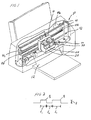
- an ink jet printing apparatus 10 constructed in accordance with the present invention. It includes a first print cartridge 20 for ejecting first droplets and a second print cartridge 30 for ejecting second droplets.
- the cartridges 20 and 30 are supported in a carrier 40 which, in turn, is slidably supported on a guide rail 42.
- a drive mechanism 44 is provided for effecting reciprocating movement of the carrier 40 back and forth along the guide rail 42.
- the drive mechanism 44 includes a motor 44a with a drive pulley 44b and a drive belt 44c which extends about the drive pulley 44b and an idler pulley 44d.
- the carrier 40 is fixedly connected to the drive belt 44c so as to move with the drive belt 44c.
- Operation of the motor 44a effects back and forth movement of the drive belt 44c and, hence, back and forth movement of the carrier 40 and the print cartridges 20 and 30.
- the print cartridges 20 and 30 move back and forth, they eject ink droplets onto a paper substrate 12 provided below them.
- the first print cartridge 20 comprises a first reservoir 22 filled with ink and a first printhead 24, see Figs. 3 and 4, which is adhesively or otherwise joined to the reservoir 22.
- the second print cartridge 30 comprises a second reservoir 32 filled with ink and a second printhead 34, see Fig. 5.
- the first and second reservoirs 22 and 32 preferably comprise polymeric containers. The reservoirs 22 and 32 may be refilled with ink.
- the first printhead 24 comprises a first heater chip 50 having a plurality of first resistive heating elements 52.
- the first printhead 24 further includes a first plate 54 having a plurality of first openings 56 extending through it which define a plurality of first orifices 56a through which first droplets of a first size are ejected.
- the first droplets are black.
- the first plate 54 may be bonded to the first chip 50 via any art recognized technique, including a thermocompression bonding process.
- sections 54a of the first plate 54 and portions 50a of the first heater chip 50 define a plurality of first bubble chambers 55.
- Ink supplied by the reservoir 22 flows into the bubble chambers 55 through ink supply channels 58.
- the first resistive heating elements 52 are positioned on the heater chip 50 such that each bubble chamber 55 has only one first heating element 52.
- Each bubble chamber 55 communicates with one first orifice 56a, see Fig. 4.
- the second printhead 34 comprises a second heater chip 60 having a plurality of second resistive heating elements 62.
- the second printhead 34 further includes a second plate 64 having a plurality of second openings 66 extending through it which define a plurality of second orifices 66a.
- second color droplets of either cyan, magenta or yellow ink are ejected through the second orifices 66a.
- the second droplets have a second size which is generally less than that of the first droplets. It is also contemplated that the first and second droplets may be of the same size.
- the second plate 64 may be bonded to the second chip 60 in the same manner that the first plate 54 is bonded to the first chip 50.
- sections 64a of the second plate 64 and portions 60a of the second heater chip 60 define a plurality of second bubble chambers 65, see Fig. 5.
- Each bubble chamber 65 is provided with a single heating element 62 and communicates with a single second orifice 66a.
- the first and second resistive heating elements 52 and 62 are individually addressed by warming and firing voltage pulses P 1 and P 2 separated by a delay period t 2 , see Fig. 2.
- the warming pulse P 1 has a pulse width t 1 and a voltage amplitude A and the firing pulse P 2 has a pulse width t 3 and, in the illustrated embodiment, the same voltage amplitude as the warming pulse P 1 .
- those pulses are provided by a driver circuit 70, see Fig. 15.
- the ink-heating element interface temperature climbs at a rate exceeding 100 million °C per second.
- the ink reaches the superheat limit (about 330°C)
- it nucleates, or explodes into vapor.
- the water vapor in the bubble has low diffusivity, so the ink is substantially thermally disconnected from the heating element once nucleation or bubble growth begins.
- bubble growth is fed by the thermal energy stored in the ink, i.e., the thermal energy transferred by the heating element to the liquid phase of the ink before the vapor phase separates the liquid ink from the surface of the heating element.
- the function of the bubble is to displace ink within the bubble chamber such that a droplet of ink is expelled from the bubble chamber orifice.
- the warming pulse causes a first quantity of thermal energy to be transferred by the heating element to the liquid ink while the firing pulse effects the transfer of a second quantity of thermal energy to the liquid ink.
- the warming pulse does not result in the ink being heated to its superheat limit.
- the first quantity of thermal energy is allowed to diffuse or "soak" into the liquid ink during the delay period.
- the layer of ink surrounding the heating element into which thermal energy has been transferred by the heating element is defined herein as the "thermal boundary layer”. It extends from about 0.1 micron to about 1.5 microns, including all ranges subsumed therein, and preferably from about 0.7 micron to about 1.2 microns into the layer of ink just above the heating element after the warming pulse P 1 , and from about 2.5 microns to about 4.0 microns, including all ranges subsumed therein, and preferably from about 2.7 microns to about 3.2 microns into the ink after the heating pulse P 2 .
- the ink forming the thermal boundary layer has a temperature which exceeds the temperature of the remaining ink in the bubble chamber by more than 0°C and preferably by about 1.0°C or more.
- the temperature of the ink immediately above the heating element just after the warming pulse is greater than about 60°C and preferably is greater than about 100°C, and more preferably is greater than about 150°C, but is less than 250°c.
- the temperature of the ink immediately above the heating element just after the delay period is greater than about 100°C, and more preferably is greater than about 120°C.
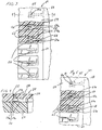
- a heating element having a resistance of about 28 Q, a width of about 32.5 ⁇ and a length of about 32.5 ⁇ m. which received a warming pulse P 1 having an amplitude of about 11.75 V and a pulse width t 1 equal to about 0.3 ⁇ s, and a firing pulse P 2 having an amplitude of about 11.75 V and a pulse width t 3 equal to about 1.3 ⁇ s separated from the warming pulse P 1 by a delay period t 2 equal to about 0.9 ⁇ s.
- a delay period t 2 equal to about 0.9 ⁇ s.
- the thermal boundary layer 200 extended about 0.8 micron in the Y direction above the surface of the heating element after the warming pulse P 1 and about 2.8 microns above the heating element after the firing pulse P 2 .
- the interface between the ink and the heating element cools while the thermal energy generated as a result of the warming pulse diffuses into the ink. This diffused energy combines with the thermal energy generated by the firing pulse to increase the size of the thermal boundary layer prior to nucleation.
- Fig. 6B illustrative simulation results are shown for a heating element having a resistance of about 28 ⁇ , a width of about 32.5 ⁇ and a length of about 32.5 ⁇ which received a warming pulse P 1 having an amplitude of about 11.75 V and a pulse width t 1 equal to about .5 ⁇ s, and a firing pulse P 2 having an amplitude of about 11.75 V and a pulse width t 3 equal to about 1.1 ⁇ s separated from the warming pulse P 1 by a delay period t 2 equal to about 2.0 ⁇ s.
- the thermal boundary layer extended about 1.1 microns in the Y-direction above the surface of the heating element after the warming pulse P 2 and about 3.1 microns above the heating element after the firing pulse P 2 .
- Fig. 6C illustrative simulation results are shown for a heating element having the same resistance and dimensions as the heating elements in the Fig. 6A and Fig. 6B examples. It received a firing pulse having an amplitude of about 11.75 V and a pulse width of about 1.6 ⁇ s. Hence, a warming pulse and a delay period were not provided.
- the thermal boundary layer extended only 2.46 microns above the surface of the heating element after the firing pulse. Further, only .216 ⁇ J of energy had been transferred to the thermal boundary at the time of nucleation as compared to .300 ⁇ J of energy in the Fig. 6A example and .346 ⁇ J of energy in the Fig. 6B example. While the total amount of energy delivered to the heating element is the same as in the Fig. 6A and Fig. 6B examples, it is evident that splitting the firing pulse into at least two pulses increases the thermal efficiency of the printhead.
- Ink in the bubble chamber which does not form part of the thermal boundary layer preferably has a temperature which is from about 20°C to about 50°C, and most preferably is greater than about 25°C but less than about 50°C.
- the temperature of the ink beyond the thermal boundary layer and in the ink supply channels 58 and 68 may be controlled by adjusting the temperature of the heater chips 50 and 60 via substrate heaters, as disclosed in patent application, U.S. Patent No. 5,734,392, entitled "INK JET PRINTHEAD HEATING DURING MARGIN PERIODS".
- the thermal boundary layer preferably fills more than 0% and less than 10%, and preferably between about 3% to about 5% of the volume of the bubble chamber, and is located directly above the heating element and below the bubble chamber orifice.
- the thermal boundary layer preferably fills more than 10% and less than 20%, and preferably between about 10% to about 15% of the volume of the bubble chamber, and is located directly above the heating element and below the bubble chamber orifice.
- the warming pulse results in an increase in the amount of thermal energy stored in the ink prior to nucleation, i.e., an increase in the size of the thermal boundary layer 200.
- This increase in stored thermal energy corresponds to an increase in the amount of fuel available to power the growth of the ejection bubble.
- Thermal energy stored in the thermal boundary layer at the time of nucleation was .300 ⁇ J in the Fig. 6A example, .346 ⁇ J in the Fig. 6B example and .216 ⁇ J in the Fig. 6C example.
- stored energy increased when a warming pulse and a delay period were used as demonstrated by these results.
- the resulting ejection bubble has increased momentum.
- a bubble having increased momentum results in an ejected ink droplet having increased momentum.
- the increase in droplet momentum is due to a significant extent to an increase in droplet velocity rather than droplet mass.
- the delay period is preferably from about .5 ⁇ s to about 2.0 ⁇ s. If the delay period is too short, the ink-heating element interface temperature will remain relatively high during application of the firing pulse to the heating element. As a result, nucleation will occur during the early part of the firing pulse, thereby decreasing the amount of time thermal energy may be transferred by the heating element to the liquid ink before the vapor phase separates the liquid ink from the surface of the heating element. If the delay period is too long, the thermal energy transferred to the liquid ink during the application of the warming pulse to the heating element will diffuse into the ink located away from the heating element or into the structure of the printhead. An acceptable balance is believed to exist between ink-heating element interface temperature and thermal diffusion when the delay period is from about .5 ⁇ s to about 2.0 ⁇ s.
- a 600 dots per inch (DPI) mono, i.e., black aqueous-based ink, printing apparatus was used. Data was taken with and without a delay period being provided.
- each firing pulse had a pulse width of 1.6 ⁇ s and an amplitude of about 11.75 V.
- each warming pulse had a pulse width of about .3 ⁇ s and an amplitude of about 11.75 V
- each firing pulse had a pulse width of about 1.3 ⁇ s and an amplitude of about 11.75 V
- the delay period was .9 ⁇ s.
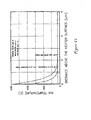
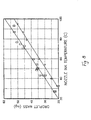
- Fig. 7 droplet velocity vs. nozzle ink temperature is plotted and in Fig. 8, droplet mass vs. nozzle ink temperature is plotted.
- a delay period was provided when the rectangular data points were collected and no delay period was provided when the circular data points were collected.
- Nozzle ink temperature is the temperature of the ink flowing into and filling the bubble chamber. It is apparent from this data that, with or without a delay period, droplet velocity and droplet mass increase as nozzle ink temperature increases. This occurs because the viscosity of the ink in the bubble chamber decreases as its temperature increases.
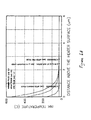
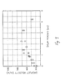
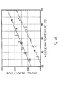
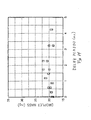
- Fig. 9 droplet velocity vs. delay period is plotted and in Fig. 10, droplet mass vs. delay period is plotted.
- the data plotted in Figs. 9 and 10 was taken when a warming pulse P 1 having an amplitude of about 11.75 V and a pulse width t 1 equal to about .3 ⁇ s, and a firing pulse P 2 having an amplitude of about 11.75 V and a pulse width t 3 equal to about 1.3 ⁇ s were applied to the heating elements.
- the combined energy of one warming pulse P 1 and one firing pulse P 2 equaled the total amount of energy supplied by the single 1.6 ⁇ s firing pulse noted above.
- Nozzle ink temperature was approximately 28°C. As can be seen from Fig.
- droplet velocity increased above about 420 inch/s when a delay period greater than about 1 ⁇ s was used.
- Droplet velocity was about 310 inch/s when a 0 delay period was used and a 1.6 ⁇ s firing pulse was applied.
- droplet velocity increased by about 36%, as determined by the following equation: % change in velocity ( ( V DP - V 0 ) / V 0 ) ⁇ 100 where
- Mass also increased when the delay period exceeded about 1 ⁇ s. The increase was slight as droplet mass stayed below about 28.0 ng. Droplet mass was about 23.0 ng when a 0 delay period was used and a 1.6 ⁇ s firing pulse was applied. Thus, droplet mass increased by about 22%, as determined by the following equation: % change in mass ( ( M DP - M 0 ) / M 0 ) ⁇ 100 where
- nozzle ink temperature In order to achieve a droplet velocity of about 420 inch/s without a delay period, nozzle ink temperature must be raised to about 80°C, see Fig. 7. At that temperature, droplet mass is approximately 43.0 ng, see Fig. 8. When a delay period of about 1.2 ⁇ s is used, a similar droplet velocity can be attained (i.e., about 420 inch/s), but droplet mass is much smaller, i.e., about 26 ng, see Figs. 9 and 10.
- each firing pulse had a pulse width of 1.6 ⁇ s and an amplitude of about 11.75 V.
- each warming pulse had a pulse width of about .3 ⁇ s and an amplitude of about 11.75 V
- each firing pulse had a pulse width of about 1.3 ⁇ s and an amplitude of about 11.75 V 1 and the delay period was .9 ⁇ s.
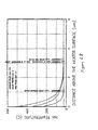
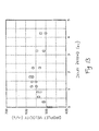
- Fig. 13 droplet velocity vs. delay period is plotted and in Fig. 14, droplet mass vs. delay period is plotted.
- the data plotted in Figs. 13 and 14 was taken when a warming pulse P 1 having an amplitude of about 11.75 V and a pulse width t 1 equal to about .3 ⁇ s, and a firing pulse P 2 having an amplitude of about 11.75 V and a pulse width t 3 equal to about 1.3 ⁇ s were applied to the heating elements.
- the combined energy of one warming pulse P 1 and one firing pulse P 2 equaled the total amount of energy supplied by the single 1.6 ⁇ s firing pulse noted above.
- Nozzle ink temperature was approximately 28°C. As can be seen from Fig.
- droplet velocity was equal to or exceeded about 550 inch/s when a delay period between about 1 ⁇ s and 2 ⁇ s was used. Droplet velocity was about 475 inch/s when a 0 delay period was used. Thus, droplet velocity increased by about 16% when a delay period was used. Droplet mass also increased when the delay period was between about 1 ⁇ s and 2 ⁇ s. It was equal to or less than about 22.0 ng. Droplet mass was about 18 ng when a 0 delay period was used. Thus, droplet mass increased by about 22% when a delay period was used.
- an increase in droplet velocity can be attained without a significant increase in droplet mass occurring.
- print quality is largely dependent on spot size and spot size is dependent on droplet mass.
- a substantial increase in droplet mass resulting from increased nozzle ink temperature would degrade the imaging capability of the device.
- the nozzle ink temperature raises significantly above the reservoir ink temperature, dissolved air will come out of solution and may prevent high speed jetting by accumulating air pockets in the bubble chamber.
- the ink droplets are less likely to be diverted from their intended straight-line paths by ink which has collected on the outer surface of the printhead.
- the warming pulse width t 1 is from about .1 ⁇ s to about .5 ⁇ s
- the firing pulse width t 3 is from about 1.0 ⁇ s to about 3.0 ⁇ s
- the warming pulse voltage amplitude is substantially equal to the firing pulse voltage amplitude
- the total energy density applied to each of the first and second heating elements by the combination of the warming pulse P 1 and the firing pulse P 2 is between about 3000 J/m 2 and about 5000 J/m 2 and heating element power density is greater than about 2 GW/m 2
- droplet velocity is increased from about 10% to about 40% and preferably from about 20% to about 40% while droplet mass is increased no more than about 20% to about 25% in comparison to droplets resulting from the same heating elements receiving only a firing pulse (i.e., a single pulse rather than two pulses separated by a delay period) having a pulse width from about 1.5 ⁇ s to about 3.0 ⁇ s, which
- resulting droplets have a mass of about 10 ng to about 40 ng and are ejected at a velocity of about 300 inch/s to about 700 inch/s. More specifically, for mono printers, the droplets have a mass of about 20 ng to about 40 ng and are ejected at a velocity of about 300 inch/s to about 600 inch/s and for color printers, the droplets have a mass of about 10 ng to about 25 ng and are ejected at a velocity of about 400 inch/s to about 700 inch/s in a direction substantially normal to the upper surface of the heating element.
- the first print cartridge 20 further comprises a first print cartridge enable circuit 26, see Fig. 15.
- the first enable circuit 26 comprises thirteen first field effect transistors (FETs) 26a.
- the second print cartridge 30 further comprises a second print cartridge enable circuit 36 which comprises thirteen second field effect transistors 36a.
- the driver circuit 70 comprises a microprocessor 72, an application specific integrated circuit (ASIC) 74, a print cartridge select circuit 80 and a common drive circuit 90.
- ASIC application specific integrated circuit
- the print cartridge select circuit 80 selectively enables one of the first print cartridge 20 and the second print cartridge 30. It has a first output 80a which is electrically coupled to the gates of the first FETs 26a via conductor 80b. It also has a second output 80c which is electrically coupled to the gates of the second FETs 36a via a conductor 80d. Thus, a first print cartridge select signal present at the first output 80a is used to select the operation of the first cartridge 20 while a second print cartridge select signal present at the second output 80c is used to select the operation of the second cartridge 30.
- the print cartridge select circuit 80 is electrically coupled to the ASIC 74 and generates appropriate print cartridge select signals in response to command signals received from the ASIC 74.
- the plurality of first resistive heating elements 52 are divided into groups. In the illustrated embodiment, thirteen first groups 52a, each having sixteen first heating elements 52, are provided.
- the plurality of second resistive heating elements 62 are similarly divided into thirteen second groups 62a, each having sixteen second heating elements 62.
- the common drive circuit 90 comprises a plurality of drivers 92 which are electrically coupled to a power supply 100 and to the plurality of first and second resistive heating elements 52 and 62.
- sixteen drivers 92 are provided.
- Each of the sixteen drivers 92 is electrically coupled to one of the sixteen first heating elements 52 in each of the thirteen first groups 52a and to one of the sixteen second heating elements 62 in each of the thirteen second groups 62a.
- each of the drivers 92 is coupled to thirteen first heating elements 52 and thirteen second heating elements 62.
- the drivers 92 may comprise field effect transistors or bipolar transistors.
- the first print cartridge 20 further comprises a first heating element drive circuit 28 electrically coupled to the first heating elements 52 and the thirteen first field effect transistors (FETs) 26a.
- the first heating element drive circuit 28 comprises thirteen groups of sixteen third field effect transistors (FETs) 28a.
- the FETs 28a in each of the thirteen groups are connected at their gates to the source of one of the thirteen first FETs 26a via conductors 28b, see Fig. 15.
- the drain of each of the third FETs 28a is electrically coupled to one of the first heating elements 52.
- the source of each of the third FETs 28a is connected to ground.
- the second print cartridge 30 further comprises a second heating element drive circuit 38 electrically coupled to the second heating elements 62 and the thirteen second field effect transistors (FETs) 36a.
- the second heating element drive circuit 38 comprises thirteen groups of sixteen fourth field effect transistors (FETs) 38a.
- the FETs 38a in each of the thirteen groups are connected at their gates to the source of one of the thirteen second FETs 36a via conductors 38b.
- the drain of each of the fourth FETs 38a is electrically coupled to one of the second heating elements 62.
- the source of each of the fourth FETs 38a is connected to ground.
- the driver circuit 70 further comprises a resistive heating element group select circuit 76 comprising a plurality of select drivers 76a, thirteen in the illustrated embodiment.
- the thirteen select drivers 76a are each connected to the drain of one of the first FETs 26a and to the drain of one of the second FETs 36a.
- the ASIC 74 sequentially generates thirteen select signals to the thirteen select drivers 76a. Thus, in the illustrated embodiment, only a single select driver 76a is activated at any given time.
- the specific group that is enabled depends upon which select driver 76a has been activated by the ASIC 74 and which print cartridge has been enabled by the print cartridge select circuit 80. Any number, i.e., 0 to 16, of the sixteen heating elements within the selected group may be fired. The specific number fired depends upon print data received by the microprocessor 72 from a separate processor (not shown) electrically coupled to it. The microprocessor 72 generates signals which are passed to the ASIC 74 and, in turn, the ASIC 74 generates appropriate warming and firing signals which are passed to the sixteen drivers 92.
- the activated drivers 92 then apply warming and firing voltage pulses to the heating elements to which they are coupled.
- the warming and firing voltage pulses applied to the first heating elements 52 have substantially the same amplitude and pulse width and are separated by substantially the same delay period as those applied to the second heating elements 62.
- the second heating elements 52 have a generally square shape. They may, however, have a rectangular or other geometric shape and/or may have a resistance which differs from that of the first heating elements as discussed in concurrently filed patent application, U.S. Patent No. 6,234,612, entitled "INKJET PRINTING APPARATUS HAVING FIRST AND SECOND PRINT CARTRIDGES RECEIVING ENERGY PULSES FROM A COMMON DRIVE CIRCUIT," by Robert W. Cornell et al.
- the printing apparatus may have only a single print cartridge. It is further contemplated that the warming pulse may have a different amplitude A than that of the firing pulse.
Landscapes
- Particle Formation And Scattering Control In Inkjet Printers (AREA)
- Ink Jet (AREA)
Claims (24)
- Tintenstrahldruckvorrichtung (10), umfassend:eine Druckpatrone (20, 30), umfassend mindestens ein Widerstandsheizelement (52) in mindestens einer Tinte enthaltenden Kammer (55) mit einer Durchtrittsöffnung (56); undeine Treiberschaltung (70), die mit der Druckpatrone elektrisch gekoppelt ist, die angeordnet ist, um einen Erwärmungsimpuls (P1) und einen Feuerimpuls (P2), die durch eine Verzögerungszeit (t2) voneinander getrennt sind, auf das Widerstandsheizelement aufzubringen, wobei der Erwärmungsimpuls bewirkt, dass das Widerstandsheizelement einen zu dem Heizelement benachbarten Teil der Tinte auf eine Temperatur erwärmt, die unter der Überhitzungsgrenze der Tinte liegt, und wobei der Feuerimpuls bewirkt, dass das Widerstandsheizelement eine Dampfblase in der Kammer erzeugt, die bewirkt, dass ein Tröpfchen von Tinte aus der Kammerdurchtrittsöffnung ausgeschleudert wird, wobei der Feuerimpuls eine Impulsbreite von zwischen 1,0 µs und 3,0 µs aufweist; undwobei die Verzögerungszeit zwischen 0,5 µs und 2,0 µs ist; dadurch gekennzeichnet, dassder Erwärmungsimpuls eine Impulsbreite von zwischen 0,1 µs und 0,5 µs aufweist; und wobeieine Energiedichte von zwischen 3000 J/m2 und 5000 J/m2. und eine Leistungsdichte größer als 2 GW/m2 auf das mindestens eine Widerstandsheizelement aufgebracht werden.
- Tintenstrahldruckvorrichtung nach Anspruch 1, bei der der Erwärmungsimpuls eine Bildung einer thermischen Grenzschicht in der Kammer hervorruft, wobei die thermische Grenzschicht etwa 3% bis etwa 5% des volumens der Kammer einnimmt, nachdem der Erwärmungsimpuls auf das Heizelement aufgebracht worden ist.
- Tintenstrahldruckvorrichtung nach Anspruch 2, bei der die thermische Grenzschicht in der Kammer vorhanden ist, wenn der Feuerimpuls aufgebracht wird.
- Tintenstrahldruckvorrichtung nach Anspruch 1, 2 oder 3, bei der das Tröpfchen von Tinte eine Masse von etwa 20 Nanogramm bis etwa 40 Nanogramm aufweist und aus der Kammerdurchtrittsöffnung mit einer Geschwindigkeit von 300 Inch/s (8 m/s) bis 600 Inch/s (15 m/s) ausgeschleudert wird.
- Tintenstrahldruckvorrichtung nach Anspruch 1, 2 oder 3, bei der das Tröpfchen von Tinte eine Masse von 10 Nanogramm bis etwa 25 Nanogramm aufweist und aus der Kammerdurchtrittsöffnung mit einer Geschwindigkeit von 400 Inch/s (10 m/s) bis etwa 700 Inch/s (18 m/s) ausgeschleudert wird.
- Tintenstrahldruckvorrichtung nach einem vorangehenden Anspruch, bei der die Druckpatrone eine Mehrzahl von Widerstandsheizelementen und eine Mehrzahl von Tinte enthaltenden Kammern mit einer Mehrzahl von Durchtrittsöffnungen umfasst.
- Tintenstrahldruckvorrichtung nach Anspruch 6, bei der die Druckpatrone umfasst:eine Deckplatte (54) mit einer Mehrzahl von darin ausgebildeten Öffnungen (56), die die Durchtrittsöffnungen begrenzen; undeinen Heizerchip (50) mit der Mehrzahl von Widerstandsheizelementen, die darauf ausgebildet sind, wobei die Deckplatte mit dem Heizerchip gekoppelt ist, so dass Abschnitte der Deckplatte und Teile des Heizerchip die Mehrzahl von Tinte enthaltenden Kammern begrenzen und die Mehrzahl von Widerstandsheizelementen auf dem Heizerchip positioniert sind, so dass jede der Tinte enthaltenen Kammern eines von den Heizelementen darin angeordnet aufweist.
- Tintenstrahldruckvorrichtung nach einem vorangehenden Anspruch, bei der die Druckpatrone weiter ein mit Tinte gefülltes Reservoir (22, 32) umfasst.
- Tintenstrahldruckvorrichtung nach Anspruch 8, bei der das Reservoir mit Tinte nachgefüllt werden kann.
- Tintenstrahldruckvorrichtung nach einem vorangehenden Anspruch, bei der die Temperatur einer Schicht von Tinte direkt über dem Heizelement nach dem Erwärmungsimpuls 150°C überschreitet. ,
- Tintenstrahldruckvorrichtung nach Anspruch 10, bei der die Temperatur einer Schicht von Tinte direkt über dem Heizelement nach der Verzögerungszeit 100°C überschreitet.
- Verfahren zum Ausschleudern eines Tröpfchens von Flüssigkeit aus einer Durchtrittsöffnung (56) einer Flüssigkeit enthaltenden Kammer (55), wobei das Verfahren die Schritte umfasst:Heizen eines Teils der Flüssigkeit, der zu einem Widerstandsheizelement (52) in der Flüssigkeit enthaltenden Kammer benachbart ist, auf eine Temperatur, die unter der Überhitzungsgrenze der Flüssigkeit liegt, indem ein Erwärmungsimpuls (P1) durch das Widerstandsheizelement hindurchgeschickt wird; undErzeugen einer Dampfblase in der Kammer, um ein Tröpfchen von Flüssigkeit aus der Durchtrittsöffnung auszuschleudern, indem ein Feuerimpuls (P2) durch das Widerstandsheizelement hindurchgeschickt wird, der Feuerimpuls um eine Verzögerungszeit (t2) von zwischen 0,5 µs und 2,0 µs nach dem Erwärmungsimpuls verzögert wird, und wobei der Feuerimpuls eine Impulsbreite von zwischen 1,0 µs und 3,0 µs aufweist, dadurch gekennzeichnet, dassder Erwärmungsimpuls eine Impulsbreite von zwischen 0,1 µs und 0,5 µs aufweist; und wobeieine Energiedichte von zwischen 3000 J/m2 und 5000 J/m2 und eine Leistungsdichte größer als 2 GW/m2 auf das mindestens eine Widerstandsheizelement aufgebracht werden.
- Verfahren nach Anspruch 12, bei dem die Flüssigkeit Tinte umfasst.
- Druckpatrone (20, 30), umfassend:mindestens ein Widerstandsheizelement (52) in mindestens einer Tinte enthaltenden Kammer (55) mit einer Durchtrittsöffnung (56); undeine Heizertreiberschaltung (70), die mit dem mindestens einen Heizelement elektrisch gekoppelt ist, die angeordnet ist, um einen Erwärmungsimpuls (P1) und einen Feuerimpuls (P2), die durch eine Verzögerungszeit (t2) voneinander getrennt sind, auf das Widerstandsheizelement aufzubringen, wobei der Erwärmungsimpuls bewirkt, dass das Widerstandsheizelement einen zu dem Heizelement benachbarten Teil der Tinte auf eine Temperatur erwärmt, die unter der Überhitzungsgrenze der Flüssigkeit liegt, und wobei der Feuerimpuls bewirkt, dass das Widerstandsheizelement eine Dampfblase in der Kammer erzeugt, die bewirkt, dass ein Tröpfchen von Tinte aus der Kammerdurchtrittsöffnung ausgeschleudert wird, wobei die Verzögerungszeit zwischen 0,5 µs und 2,0 µs ist, wobei der Feuerimpuls eine Impulsbreite von zwischen 1,0 µs und 3,0 µs aufweist, dadurch gekennzeichnet, dass der Erwärmungimpuls eine Impulsbreite von zwischen 0,1 µs und 0,5 µs aufweist; und wobeieine Energiedichte von zwischen 3000 J/m2 und 5000 J/m2 und eine Leistungsdichte größer als 2 GW/m2 auf das mindestens eine Widerstandsheizelement aufgebracht werden.
- Druckpatrone nach Anspruch 14, bei der der Erwärmungsimpuls eine Bildung einer thermischen Grenzschicht in der Kammer hervorruft, wobei die thermische Grenzschicht 3% bis 5% des Volumens der Kammer einnimmt, nachdem der Erwärmungsimpuls auf das Heizelement aufgebracht worden ist.
- Druckpatrone nach Anspruch 15, bei der die thermische Grenzschicht in der Kammer vorhanden ist, wenn der Feuerimpuls aufgebracht wird.
- Druckpatrone nach Anspruch 14, 15 oder 16, bei der das Tröpfchen von Tinte eine Masse von 20 Nanogramm bis 40 Nanogramm aufweist und aus der Kammerdurchtrittsöffnung mit einer Geschwindigkeit von 300 Inch/s (8 m/s) bis 600 Inch/s (15 m/s) ausgeschleudert wird.
- Druckpatrone nach Anspruch 14, 15 oder 16, bei der das Tröpfchen von Tinte eine Masse von 10 Nanogramm bis 25 Nanogramm aufweist und aus der Kammerdurchtrittsöffnung mit einer Geschwindigkeit von 400 Inch/s (10 m/s) bis 700 Inch/s (18 m/s) ausgeschleudert wird.
- Druckpatrone nach einem der Ansprüche 14 bis 18, wobei die Druckpatrone eine Mehrzahl von Widerstandsheizelementen und eine Mehrzahl von Tinte enthaltenden Kammern mit einer Mehrzahl von Durchtrittsöffnungen umfasst.
- Druckpatrone nach Anspruch 19, umfassend:eine Deckplatte (54) mit einer Mehrzahl von darin ausgebildeten Öffnungen, die die Durchtrittsöffnungen begrenzen; undeinen Heizerchip (50) mit der Mehrzahl von Widerstandsheizelementen, die darauf ausgebildet sind, wobei die Deckplatte mit dem Heizerchip gekoppelt ist, so dass Abschnitte der Deckplatte und Teile des Heizerchip die Mehrzahl von Tinte enthaltenden Kammern begrenzen und die Mehrzahl von Widerstandsheizelementen auf dem Heizerchip positioniert sind, so dass jede der Tinte enthaltenden Kammern eines von den Heizelementen darin angeordnet aufweist.
- Druckpatrone nach einem der Ansprüche 14 bis 20, weiter umfassend ein mit Tinte gefülltes Reservoir.
- Druckpatrone nach Anspruch 21, bei der das Reservoir mit Tinte nachgefüllt werden kann.
- Druckpatrone nach einem der Ansprüche 14 bis 22, bei der die Temperatur einer Schicht von Tinte direkt über dem Heizelement nach dem Erwärmuhgsimpuls 150°C überschreitet.
- Druckpatrone nach einem der Ansprüche 14 bis 23, bei der die Temperatur einer Schicht von Tinte direkt über dem Heizelement nach der Verzögerungszeit 100°C überschreitet.
Priority Applications (1)
| Application Number | Priority Date | Filing Date | Title |
|---|---|---|---|
| EP04027292A EP1514687A3 (de) | 1997-03-25 | 1998-03-25 | Tintenstrahldrucker und Druckverfahren |
Applications Claiming Priority (2)
| Application Number | Priority Date | Filing Date | Title |
|---|---|---|---|
| US08/823,594 US6296350B1 (en) | 1997-03-25 | 1997-03-25 | Ink jet printer having driver circuit for generating warming and firing pulses for heating elements |
| US823594 | 1997-03-25 |
Related Child Applications (1)
| Application Number | Title | Priority Date | Filing Date |
|---|---|---|---|
| EP04027292A Division EP1514687A3 (de) | 1997-03-25 | 1998-03-25 | Tintenstrahldrucker und Druckverfahren |
Publications (3)
| Publication Number | Publication Date |
|---|---|
| EP0867286A2 EP0867286A2 (de) | 1998-09-30 |
| EP0867286A3 EP0867286A3 (de) | 2000-03-29 |
| EP0867286B1 true EP0867286B1 (de) | 2007-05-23 |
Family
ID=25239187
Family Applications (2)
| Application Number | Title | Priority Date | Filing Date |
|---|---|---|---|
| EP98302294A Expired - Lifetime EP0867286B1 (de) | 1997-03-25 | 1998-03-25 | Tintenstrahldrucker und Tintenstrahldruckverfahren |
| EP04027292A Withdrawn EP1514687A3 (de) | 1997-03-25 | 1998-03-25 | Tintenstrahldrucker und Druckverfahren |
Family Applications After (1)
| Application Number | Title | Priority Date | Filing Date |
|---|---|---|---|
| EP04027292A Withdrawn EP1514687A3 (de) | 1997-03-25 | 1998-03-25 | Tintenstrahldrucker und Druckverfahren |
Country Status (7)
| Country | Link |
|---|---|
| US (1) | US6296350B1 (de) |
| EP (2) | EP0867286B1 (de) |
| JP (1) | JPH10291315A (de) |
| KR (1) | KR19980080614A (de) |
| CN (1) | CN1083333C (de) |
| DE (1) | DE69837797T2 (de) |
| TW (1) | TW419423B (de) |
Families Citing this family (18)
| Publication number | Priority date | Publication date | Assignee | Title |
|---|---|---|---|---|
| US6443561B1 (en) | 1999-08-24 | 2002-09-03 | Canon Kabushiki Kaisha | Liquid discharge head, driving method therefor, and cartridge, and image forming apparatus |
| US6986566B2 (en) | 1999-12-22 | 2006-01-17 | Eastman Kodak Company | Liquid emission device |
| US6575563B1 (en) | 2002-08-05 | 2003-06-10 | Lexmark International, Inc. | Power/volume regime for ink jet printers |
| US6957886B2 (en) | 2002-09-27 | 2005-10-25 | Eastman Kodak Company | Apparatus and method of inkjet printing on untreated hydrophobic media |
| US6736489B1 (en) * | 2002-11-23 | 2004-05-18 | Silverbrook Research Pty Ltd | Thermal ink jet printhead with low heater mass |
| US7328978B2 (en) * | 2002-11-23 | 2008-02-12 | Silverbrook Research Pty Ltd | Printhead heaters with short pulse time |
| US6719405B1 (en) | 2003-03-25 | 2004-04-13 | Lexmark International, Inc. | Inkjet printhead having convex wall bubble chamber |
| US7341324B2 (en) * | 2003-10-22 | 2008-03-11 | Hewlett-Packard Development Company, L.P. | Pre-warming portions of an inkjet printhead |
| US9283750B2 (en) * | 2005-05-20 | 2016-03-15 | Hewlett-Packard Development Company, L.P. | Constant current mode firing circuit for thermal inkjet-printing nozzle |
| US20070024652A1 (en) * | 2005-07-29 | 2007-02-01 | Lexmark International, Inc. | Method and apparatus for printing |
| US7367640B2 (en) | 2005-09-30 | 2008-05-06 | Lexmark International, Inc. | Methods and apparatuses for control of a signal in a printing apparatus |
| AU2006349360A1 (en) * | 2006-10-09 | 2008-04-17 | Silverbrook Research Pty Ltd | MEMS bubble generator for large stable vapor bubbles |
| US7491911B2 (en) * | 2006-10-10 | 2009-02-17 | Silverbrook Research Pty Ltd | MEMS bubble generator for large stable vapor bubbles |
| WO2009114012A1 (en) * | 2008-03-12 | 2009-09-17 | Hewlett-Packard Development Company, L.P. | Firing signal forwarding in a fluid ejection device |
| US8556398B2 (en) * | 2010-11-16 | 2013-10-15 | Xerox Corporation | Printing system with selective heater activation to enable ink flow to a printhead in the printing system |
| US10960396B2 (en) | 2014-05-16 | 2021-03-30 | Cytonome/St, Llc | Thermal activated microfluidic switching |
| US9808812B2 (en) * | 2014-06-20 | 2017-11-07 | The Procter & Gamble Company | Microfluidic delivery system |
| WO2018203876A1 (en) | 2017-05-01 | 2018-11-08 | Hewlett-Packard Development Company, L.P. | Pause start-up routine of imaging device |
Family Cites Families (25)
| Publication number | Priority date | Publication date | Assignee | Title |
|---|---|---|---|---|
| US4313124A (en) * | 1979-05-18 | 1982-01-26 | Canon Kabushiki Kaisha | Liquid jet recording process and liquid jet recording head |
| US4490728A (en) | 1981-08-14 | 1984-12-25 | Hewlett-Packard Company | Thermal ink jet printer |
| US5285215A (en) | 1982-12-27 | 1994-02-08 | Exxon Research And Engineering Company | Ink jet apparatus and method of operation |
| US4503444A (en) | 1983-04-29 | 1985-03-05 | Hewlett-Packard Company | Method and apparatus for generating a gray scale with a high speed thermal ink jet printer |
| IT1185799B (it) | 1985-06-10 | 1987-11-18 | Olivetti & Co Spa | Dispositivo di pilotaggio per un elemento di stampa a getto selettivo d inchiostro |
| US4638337A (en) | 1985-08-02 | 1987-01-20 | Xerox Corporation | Thermal ink jet printhead |
| US4982199A (en) | 1988-12-16 | 1991-01-01 | Hewlett-Packard Company | Method and apparatus for gray scale printing with a thermal ink jet pen |
| GB8829567D0 (en) | 1988-12-19 | 1989-02-08 | Am Int | Method of operating pulsed droplet deposition apparatus |
| WO1990010541A1 (de) | 1989-03-14 | 1990-09-20 | Siemens Aktiengesellschaft | Verfahren zum variieren der tropfengrösse in tintendruckeinrichtungen |
| US5172134A (en) | 1989-03-31 | 1992-12-15 | Canon Kabushiki Kaisha | Ink jet recording head, driving method for same and ink jet recording apparatus |
| US5107276A (en) * | 1989-07-03 | 1992-04-21 | Xerox Corporation | Thermal ink jet printhead with constant operating temperature |
| JP2752491B2 (ja) | 1990-02-02 | 1998-05-18 | キヤノン株式会社 | 液体噴射記録装置 |
| US5063655A (en) | 1990-04-02 | 1991-11-12 | International Business Machines Corp. | Method to integrate drive/control devices and ink jet on demand devices in a single printhead chip |
| US5036337A (en) | 1990-06-22 | 1991-07-30 | Xerox Corporation | Thermal ink jet printhead with droplet volume control |
| DE69233179T2 (de) * | 1991-01-18 | 2004-06-17 | Canon K.K. | Tintenstrahlaufzeichnungsverfahren und Vorrichtung mit thermischer Energie |
| JP2974487B2 (ja) * | 1991-03-20 | 1999-11-10 | キヤノン株式会社 | 記録装置 |
| JP3071869B2 (ja) | 1991-05-13 | 2000-07-31 | 株式会社リコー | 液体噴射記録装置及び記録方法 |
| EP0580165B1 (de) * | 1992-07-22 | 1997-02-12 | Canon Kabushiki Kaisha | Strahlaufzeichnungsverfahren |
| JP3339724B2 (ja) * | 1992-09-29 | 2002-10-28 | 株式会社リコー | インクジェット記録方法及びその装置 |
| JP3397371B2 (ja) | 1993-05-27 | 2003-04-14 | キヤノン株式会社 | 記録装置および記録方法 |
| JP3086132B2 (ja) | 1994-07-29 | 2000-09-11 | キヤノン株式会社 | インクジェット記録装置 |
| JPH0839807A (ja) * | 1994-07-29 | 1996-02-13 | Canon Inc | インクジェットプリント方法および装置 |
| JPH08230190A (ja) * | 1995-02-23 | 1996-09-10 | Canon Inc | 記録ヘッド補正方法及びその装置及びその装置によって補正された記録ヘッド及びその記録ヘッドを用いた記録装置 |
| JPH08267775A (ja) * | 1995-03-28 | 1996-10-15 | Canon Inc | インクタンク、インクジェットユニット、およびインクジェットプリンタ |
| JP3554138B2 (ja) | 1996-06-28 | 2004-08-18 | キヤノン株式会社 | インクジェット記録方法、インクジェット記録ヘッド及びインクジェット記録装置 |
-
1997
- 1997-03-25 US US08/823,594 patent/US6296350B1/en not_active Expired - Lifetime
-
1998
- 1998-03-25 CN CN98105880A patent/CN1083333C/zh not_active Expired - Lifetime
- 1998-03-25 KR KR1019980010218A patent/KR19980080614A/ko not_active Abandoned
- 1998-03-25 DE DE69837797T patent/DE69837797T2/de not_active Expired - Lifetime
- 1998-03-25 EP EP98302294A patent/EP0867286B1/de not_active Expired - Lifetime
- 1998-03-25 EP EP04027292A patent/EP1514687A3/de not_active Withdrawn
- 1998-03-25 JP JP10119868A patent/JPH10291315A/ja active Pending
- 1998-05-22 TW TW087104464A patent/TW419423B/zh not_active IP Right Cessation
Also Published As
| Publication number | Publication date |
|---|---|
| US6296350B1 (en) | 2001-10-02 |
| KR19980080614A (ko) | 1998-11-25 |
| TW419423B (en) | 2001-01-21 |
| DE69837797T2 (de) | 2008-01-31 |
| EP0867286A3 (de) | 2000-03-29 |
| DE69837797D1 (de) | 2007-07-05 |
| EP1514687A3 (de) | 2006-04-05 |
| CN1194206A (zh) | 1998-09-30 |
| EP1514687A2 (de) | 2005-03-16 |
| JPH10291315A (ja) | 1998-11-04 |
| EP0867286A2 (de) | 1998-09-30 |
| CN1083333C (zh) | 2002-04-24 |
Similar Documents
| Publication | Publication Date | Title |
|---|---|---|
| EP0867286B1 (de) | Tintenstrahldrucker und Tintenstrahldruckverfahren | |
| US6276775B1 (en) | Variable drop mass inkjet drop generator | |
| EP0913257B1 (de) | Vorrichtung zur Erzeugung des Tintenausstosses und des Nachfüllens der Tintenkammer mit hoher Frequenz | |
| US5539437A (en) | Hybrid thermal/hot melt ink jet print head | |
| US6594899B2 (en) | Variable drop mass inkjet drop generator | |
| EP0933218A2 (de) | Hybrides Drucksystem unter Verwendung von Mehrfachströpfen und Mehrfach-Durchlauf | |
| US6259463B1 (en) | Multi-drop merge on media printing system | |
| EP0900659B1 (de) | Tintenstrahlkopf und Apparat zum Tintenstrahldrucken | |
| US5642142A (en) | Variable halftone operation inkjet printheads | |
| EP0867285B1 (de) | Tintenstrahldruckvorrichtung mit ersten und zweiten Druckpatronen, welche Energiepulse von einer gemeinsamen Treiberschaltung empfangen | |
| US6669317B2 (en) | Precursor electrical pulses to improve inkjet decel | |
| US6471326B2 (en) | Ink-jet head and ink-jet printing apparatus | |
| US6711806B2 (en) | Method of manufacturing a thermal fluid jetting apparatus | |
| JP3127646B2 (ja) | インクジェット記録装置 | |
| US6126262A (en) | Ink-jet printing apparatus and ink-jet printing method | |
| JP2840480B2 (ja) | インクジェット記録装置とその記録方法 | |
| JP2937470B2 (ja) | インクジェット記録装置 | |
| JP3631001B2 (ja) | インクジェットヘッドおよびインクジェットプリント装置 | |
| JPH07148916A (ja) | インクジェット記録ヘッド及び該記録ヘッドを備えた記録装置 | |
| JPH03213356A (ja) | インクジェット記録装置 | |
| JPH0958022A (ja) | インクジェットプリント方法およびインクジェットプリント装置 | |
| JPH06238900A (ja) | インクジェット記録ヘッドおよび該ヘッドを用いたインクジェット記録装置 |
Legal Events
| Date | Code | Title | Description |
|---|---|---|---|
| PUAI | Public reference made under article 153(3) epc to a published international application that has entered the european phase |
Free format text: ORIGINAL CODE: 0009012 |
|
| AK | Designated contracting states |
Kind code of ref document: A2 Designated state(s): DE FR GB |
|
| AX | Request for extension of the european patent |
Free format text: AL;LT;LV;MK;RO;SI |
|
| PUAL | Search report despatched |
Free format text: ORIGINAL CODE: 0009013 |
|
| AK | Designated contracting states |
Kind code of ref document: A3 Designated state(s): AT BE CH DE DK ES FI FR GB GR IE IT LI LU MC NL PT SE |
|
| AX | Request for extension of the european patent |
Free format text: AL;LT;LV;MK;RO;SI |
|
| 17P | Request for examination filed |
Effective date: 20000915 |
|
| AKX | Designation fees paid |
Free format text: DE FR GB |
|
| 17Q | First examination report despatched |
Effective date: 20040906 |
|
| GRAP | Despatch of communication of intention to grant a patent |
Free format text: ORIGINAL CODE: EPIDOSNIGR1 |
|
| GRAS | Grant fee paid |
Free format text: ORIGINAL CODE: EPIDOSNIGR3 |
|
| GRAA | (expected) grant |
Free format text: ORIGINAL CODE: 0009210 |
|
| AK | Designated contracting states |
Kind code of ref document: B1 Designated state(s): DE FR GB |
|
| REG | Reference to a national code |
Ref country code: GB Ref legal event code: FG4D |
|
| REF | Corresponds to: |
Ref document number: 69837797 Country of ref document: DE Date of ref document: 20070705 Kind code of ref document: P |
|
| ET | Fr: translation filed | ||
| PLBE | No opposition filed within time limit |
Free format text: ORIGINAL CODE: 0009261 |
|
| STAA | Information on the status of an ep patent application or granted ep patent |
Free format text: STATUS: NO OPPOSITION FILED WITHIN TIME LIMIT |
|
| 26N | No opposition filed |
Effective date: 20080226 |
|
| REG | Reference to a national code |
Ref country code: GB Ref legal event code: 732E Free format text: REGISTERED BETWEEN 20131107 AND 20131113 |
|
| REG | Reference to a national code |
Ref country code: DE Ref legal event code: R082 Ref document number: 69837797 Country of ref document: DE Representative=s name: ABITZ & PARTNER PATENTANWAELTE MBB, DE Effective date: 20131107 Ref country code: DE Ref legal event code: R082 Ref document number: 69837797 Country of ref document: DE Representative=s name: ABITZ & PARTNER, DE Effective date: 20131107 Ref country code: DE Ref legal event code: R081 Ref document number: 69837797 Country of ref document: DE Owner name: FUNAI ELECTRIC CO., LTD, DAITO CITY, JP Free format text: FORMER OWNER: LEXMARK INTERNATIONAL, INC., LEXINGTON, KY., US Effective date: 20131107 Ref country code: DE Ref legal event code: R081 Ref document number: 69837797 Country of ref document: DE Owner name: FUNAI ELECTRIC CO., LTD, JP Free format text: FORMER OWNER: LEXMARK INTERNATIONAL, INC., LEXINGTON, US Effective date: 20131107 |
|
| REG | Reference to a national code |
Ref country code: FR Ref legal event code: TP Owner name: FUNAI ELECTRIC CO LTD, JP Effective date: 20140102 |
|
| REG | Reference to a national code |
Ref country code: FR Ref legal event code: PLFP Year of fee payment: 18 |
|
| REG | Reference to a national code |
Ref country code: FR Ref legal event code: PLFP Year of fee payment: 19 |
|
| PGFP | Annual fee paid to national office [announced via postgrant information from national office to epo] |
Ref country code: FR Payment date: 20160208 Year of fee payment: 19 Ref country code: GB Payment date: 20160323 Year of fee payment: 19 |
|
| PGFP | Annual fee paid to national office [announced via postgrant information from national office to epo] |
Ref country code: DE Payment date: 20170321 Year of fee payment: 20 |
|
| GBPC | Gb: european patent ceased through non-payment of renewal fee |
Effective date: 20170325 |
|
| REG | Reference to a national code |
Ref country code: FR Ref legal event code: ST Effective date: 20171130 |
|
| PG25 | Lapsed in a contracting state [announced via postgrant information from national office to epo] |
Ref country code: FR Free format text: LAPSE BECAUSE OF NON-PAYMENT OF DUE FEES Effective date: 20170331 |
|
| PG25 | Lapsed in a contracting state [announced via postgrant information from national office to epo] |
Ref country code: GB Free format text: LAPSE BECAUSE OF NON-PAYMENT OF DUE FEES Effective date: 20170325 |
|
| REG | Reference to a national code |
Ref country code: DE Ref legal event code: R071 Ref document number: 69837797 Country of ref document: DE |