EP0867292A2 - Plaques à buses d'une imprimante à jet d'encre - Google Patents
Plaques à buses d'une imprimante à jet d'encre Download PDFInfo
- Publication number
- EP0867292A2 EP0867292A2 EP98302453A EP98302453A EP0867292A2 EP 0867292 A2 EP0867292 A2 EP 0867292A2 EP 98302453 A EP98302453 A EP 98302453A EP 98302453 A EP98302453 A EP 98302453A EP 0867292 A2 EP0867292 A2 EP 0867292A2
- Authority
- EP
- European Patent Office
- Prior art keywords
- ink supply
- height
- nozzle
- ink
- mask
- Prior art date
- Legal status (The legal status is an assumption and is not a legal conclusion. Google has not performed a legal analysis and makes no representation as to the accuracy of the status listed.)
- Withdrawn
Links
Images


Classifications
-
- B—PERFORMING OPERATIONS; TRANSPORTING
- B41—PRINTING; LINING MACHINES; TYPEWRITERS; STAMPS
- B41J—TYPEWRITERS; SELECTIVE PRINTING MECHANISMS, i.e. MECHANISMS PRINTING OTHERWISE THAN FROM A FORME; CORRECTION OF TYPOGRAPHICAL ERRORS
- B41J2/00—Typewriters or selective printing mechanisms characterised by the printing or marking process for which they are designed
- B41J2/005—Typewriters or selective printing mechanisms characterised by the printing or marking process for which they are designed characterised by bringing liquid or particles selectively into contact with a printing material
- B41J2/01—Ink jet
- B41J2/135—Nozzles
- B41J2/16—Production of nozzles
- B41J2/1621—Manufacturing processes
- B41J2/1632—Manufacturing processes machining
- B41J2/1634—Manufacturing processes machining laser machining
-
- B—PERFORMING OPERATIONS; TRANSPORTING
- B41—PRINTING; LINING MACHINES; TYPEWRITERS; STAMPS
- B41J—TYPEWRITERS; SELECTIVE PRINTING MECHANISMS, i.e. MECHANISMS PRINTING OTHERWISE THAN FROM A FORME; CORRECTION OF TYPOGRAPHICAL ERRORS
- B41J2/00—Typewriters or selective printing mechanisms characterised by the printing or marking process for which they are designed
- B41J2/005—Typewriters or selective printing mechanisms characterised by the printing or marking process for which they are designed characterised by bringing liquid or particles selectively into contact with a printing material
- B41J2/01—Ink jet
- B41J2/135—Nozzles
- B41J2/14—Structure thereof only for on-demand ink jet heads
- B41J2/14016—Structure of bubble jet print heads
- B41J2/14032—Structure of the pressure chamber
- B41J2/1404—Geometrical characteristics
-
- B—PERFORMING OPERATIONS; TRANSPORTING
- B41—PRINTING; LINING MACHINES; TYPEWRITERS; STAMPS
- B41J—TYPEWRITERS; SELECTIVE PRINTING MECHANISMS, i.e. MECHANISMS PRINTING OTHERWISE THAN FROM A FORME; CORRECTION OF TYPOGRAPHICAL ERRORS
- B41J2/00—Typewriters or selective printing mechanisms characterised by the printing or marking process for which they are designed
- B41J2/005—Typewriters or selective printing mechanisms characterised by the printing or marking process for which they are designed characterised by bringing liquid or particles selectively into contact with a printing material
- B41J2/01—Ink jet
- B41J2/135—Nozzles
- B41J2/14—Structure thereof only for on-demand ink jet heads
- B41J2/1433—Structure of nozzle plates
-
- B—PERFORMING OPERATIONS; TRANSPORTING
- B41—PRINTING; LINING MACHINES; TYPEWRITERS; STAMPS
- B41J—TYPEWRITERS; SELECTIVE PRINTING MECHANISMS, i.e. MECHANISMS PRINTING OTHERWISE THAN FROM A FORME; CORRECTION OF TYPOGRAPHICAL ERRORS
- B41J2/00—Typewriters or selective printing mechanisms characterised by the printing or marking process for which they are designed
- B41J2/005—Typewriters or selective printing mechanisms characterised by the printing or marking process for which they are designed characterised by bringing liquid or particles selectively into contact with a printing material
- B41J2/01—Ink jet
- B41J2/135—Nozzles
- B41J2/16—Production of nozzles
- B41J2/1601—Production of bubble jet print heads
- B41J2/1603—Production of bubble jet print heads of the front shooter type
-
- B—PERFORMING OPERATIONS; TRANSPORTING
- B41—PRINTING; LINING MACHINES; TYPEWRITERS; STAMPS
- B41J—TYPEWRITERS; SELECTIVE PRINTING MECHANISMS, i.e. MECHANISMS PRINTING OTHERWISE THAN FROM A FORME; CORRECTION OF TYPOGRAPHICAL ERRORS
- B41J2/00—Typewriters or selective printing mechanisms characterised by the printing or marking process for which they are designed
- B41J2/005—Typewriters or selective printing mechanisms characterised by the printing or marking process for which they are designed characterised by bringing liquid or particles selectively into contact with a printing material
- B41J2/01—Ink jet
- B41J2/135—Nozzles
- B41J2/16—Production of nozzles
- B41J2/1621—Manufacturing processes
- B41J2/1623—Manufacturing processes bonding and adhesion
-
- B—PERFORMING OPERATIONS; TRANSPORTING
- B41—PRINTING; LINING MACHINES; TYPEWRITERS; STAMPS
- B41J—TYPEWRITERS; SELECTIVE PRINTING MECHANISMS, i.e. MECHANISMS PRINTING OTHERWISE THAN FROM A FORME; CORRECTION OF TYPOGRAPHICAL ERRORS
- B41J2/00—Typewriters or selective printing mechanisms characterised by the printing or marking process for which they are designed
- B41J2/005—Typewriters or selective printing mechanisms characterised by the printing or marking process for which they are designed characterised by bringing liquid or particles selectively into contact with a printing material
- B41J2/01—Ink jet
- B41J2/135—Nozzles
- B41J2/16—Production of nozzles
- B41J2/1621—Manufacturing processes
- B41J2/1637—Manufacturing processes molding
- B41J2/1639—Manufacturing processes molding sacrificial molding
Definitions
- the invention relates to ink jet nozzle plates having improved flow characteristics and to methods for making the nozzle plates for ink jet printers.
- Printheads for ink jet printers are precisely manufactured so that the components cooperate with an integral ink reservoir to deliver ink to an ink ejection device in the printhead to achieve a desired print quality.
- a major component of the printhead of an ink jet printer is the nozzle plate which contains ink supply channels, firing chambers and ports for expelling ink from the printhead.
- nozzle plates Since the introduction of ink jet printers, nozzle plates have undergone considerable design changes in order to increase the efficiency of ink ejection and to decrease their manufacturing cost. Changes in the nozzle plate design continue to be made in an attempt to accommodate higher speed printing and higher resolution of the printed images.
- Nozzle plates are complex structures which contain multiple ejection ports or nozzles for ejecting ink and channels for feeding ink from an ink reservoir to a firing chamber associated with the nozzle being used. Pressure is created in the firing chamber to expel a droplet of ink from the chamber through the nozzle to the substrate. The pressure also forces ink out of the supply channel and may affect the ink in the supply region or via feeding other supply channels and firing chambers.
- Thermal ink jet printers use a plurality of resistance heating elements in the firing chambers to vaporize a component of the ink which then expands as a vapor bubble forcing ink out of the nozzle associated with the chamber.
- the bubble begins to contract and finally collapses onto the heater surface.
- the chamber refills by capillary action.
- the ink forms a meniscus which undergoes an oscillatory motion.
- the oscillatory motion of the meniscus tends to pull a small amount of air into the firing chamber and under certain conditions, the air may be trapped in the chamber. Trapped air may accumulate in the chamber after a number of firings. Once this happens, the performance of the nozzle degrades severely.
- Trapped air also act as a shock absorber which reduces the pumping action of the vapor bubble. If too much air is trapped in the firing chamber, it may push ink out of the ink supply channel or choke off the inlet of the channel thereby affecting the ability to refill the chamber. In addition to trapped air, debris in the ink may also effect the refilling of the firing chambers and thus the quality and efficiency of the ink ejected from the nozzles.
- Still another object of the invention is to provide a method for manufacturing nozzle plates for ink jet printers.
- a further object of the invention is to provide a method for laser ablating nozzle plates having improved ink flow characteristics.
- the invention provides a polymeric nozzle plate for a thermal ink jet printer which is comprised of a polymeric material having a thickness sufficient to provide a plurality of firing chambers disposed adjacent opposed edges of the nozzle plate, nozzle holes above each firing chamber and ink supply channels for feeding the firing chambers which are connected to an ink supply region.
- Each of the firing chambers have a firing chamber height
- each of the supply channels have a supply channel height
- the supply region has a supply region height which heights are a fraction of the thickness of the polymeric material.
- the invention provides a method for making a nozzle plate for an ink jet printer which comprises mounting a polyimide film on a movable platen, ablating firing chambers and ink supply channels associated with the firing chambers while controlling the defocus of the laser beam with respect to the polyimide material in order to form the nozzle holes and firing chambers in the polyimide film.
- the invention provides a mask for ablating a polymeric material which comprises a laser beam resistant web having regions of varying opacity from opaque to transparent containing semitransparent regions for formation of an ink supply region, a plurality of ink supply channels connected to the ink supply region and firing chambers associated with each ink supply channels.
- the mask also contains transparent regions for formation of nozzle holes in semi-transparent regions used to form the firing chambers wherein the opaque regions define the boundaries of the firing chambers, ink supply channels and ink supply region and are substantially on a periphery of the mask.
- the apparatus and methods of the invention provide improved ink jet nozzle plates which reduce problems associated with ink flow to the firing chambers and which substantially reduce manufacturing costs by simplifying the manufacturing steps. Because the nozzle holes, firing chambers and ink supply channels are all formed in the same polymeric material, alignment of separate polymeric or thick film materials containing the firing chambers and nozzles holes is not required. Also, using a mask having varying opacity to form the flow features in the same polymeric material reduces the need for using multiple masks and separate alignment steps for each mask.
- the invention provides improved nozzle plates and methods and apparatus for making the nozzle plates.
- the invention provides a nozzle plate made from a polymeric material selected from the group consisting of polyimide polymers, polyester polymers, polymethyl methacrylate polymers, polycarbonate polymers and homopolymers, copolymers and terpolymers as well as blends of two or more of the foregoing, preferably polyimide polymers, which has a thickness sufficient to contain firing chambers, ink supply channels for feeding the firing chambers and nozzles holes associated with the firing chambers.
- the polymeric material have a thickness of about 10 to about 300 microns, preferably a thickness of about 15 to about 250 microns, most preferably a thickness of about 35 to about 75 microns and including all ranges subsumed therein.
- the firing chambers and supply channels are referred to collectively as the "flow features" of the nozzle plates.
- Each nozzle plate contains a plurality of ink supply channels, firing chambers and nozzles holes which are positioned in the polymeric material so that the nozzle holes are associated with an ink propulsion device so that upon activation of the firing chamber a droplet of ink is expelled from the firing chamber through the nozzle hole to a substrate to be printed. Sequencing one or more firing chambers in rapid succession provides ink dots on the substrate which when combined with one another produce an image.
- the nozzle plates may be formed in a continuous or semi-continuous process by laser machining a polymeric material which is provided as a continuous elongate strip or film.
- sprocket holes or apertures are provided in the strip along one or both sides thereof.
- the strip of material in which the nozzle plate is formed is conventionally provided on a reel.
- Several manufacturers such as OBE of Japan and E.I. DuPont de Nemours & Co. of Wilmington, Delaware, commercially supply materials suitable for use in manufacturing the nozzle plates, under the trademarks of UPILEX or KAPTON, respectively.
- the preferred material for use in making nozzle plates is a polyimide tape containing an adhesive layer on one surface thereof.
- the adhesive layer (not shown) is preferably any B-stageable material.
- suitable B-stageable materials are thermal cure resins which include phenolic resins, resorcinol resins, urea resins, epoxy resins, ethyleneurea resins, furane resins, polyurethanes, and silicon containing resins.
- Thermoplastic or hot melt materials which may be used as an adhesive include ethylene-vinyl acetate, ethylene ethylacrylate, polypropylene, polystyrene, polyamides, polyesters and polyurethanes.
- the adhesive layer is typically about 1 to about 100 microns in thickness, preferably about 1 to about 50 microns in thickness and most preferably about 5 to about 20 microns in thickness. In the most preferred embodiment, the adhesive layer is a phenolic butyral adhesive such as that used in the laminate RFLEX R1100 or RFLEX R1000, commercially available from Rogers of Chandler, Arizona.
- the adhesive layer is preferably coated with a sacrificial layer, preferably a water soluble polymer such as polyvinyl alcohol which remains on the adhesive layer until the laser ablation of the flow features in the nozzle plate is substantially complete.
- a sacrificial layer preferably a water soluble polymer such as polyvinyl alcohol which remains on the adhesive layer until the laser ablation of the flow features in the nozzle plate is substantially complete.
- polyvinyl alcohol materials which may be used as the sacrificial layer include AIRVOL 165, available from Air Products Inc. of Allentown, Pennsylvania, EMS1146 from Emulsitone Inc. of Whippany, New Jersey, and various polyvinyl alcohol resins from Aldrich Chemical Company of Milwaukee, Wisconsin.
- the sacrificial layer is preferably at least about 1 micron in thickness and is coated onto the adhesive layer which is on the polymeric film.
- Methods such as extrusion, roll coating, brushing, blade coating, spraying, dipping, and other techniques known to the coatings industry may be used to coat the polymeric material with the adhesive and sacrificial layer. After machining the polymeric material to form the flow features therein, the sacrificial layer is be removed by dipping or spraying the polymeric material with a solvent such as water.
- Fig. 1 is a cross-sectional view not to scale of a nozzle plate 10 of the invention as seen through an ink supply channel 12, a firing chamber 14 and a nozzle hole 16.
- Fig. 2 is a plan view, not to scale, of the ink supply channel 12, firing chamber 14 and nozzle hole 16 formed in the polymeric material 18.
- a plurality of supply channels 12, firing chambers 14 and nozzle holes 16 are provided in a polymeric material 18, preferably by the laser machining techniques which will be described in more detail below.
- the nozzle plate 10 is attached to a semi-conductor substrate 20 containing an ink propulsion device 22 such as a resister for heating the ink in the firing chamber 14 (Fig. 1).
- an ink propulsion device 22 such as a resister for heating the ink in the firing chamber 14 (Fig. 1).
- a component in the ink vaporizes rapidly producing a vapor bubble which forms in the firing chamber 14 which forces a portion of ink from the firing chamber through the nozzle hole 16 so that it impacts on a substrate. Because the vapor bubble expands rapidly in all directions, it also forces ink out of the supply channel 12.
- the substrate Prior to attaching the nozzle plate to the substrate, it is preferred to coat the substrate with a thin layer of photocurable epoxy resin to enhance the adhesion between the nozzle plate and the substrate and to fill in all topographical features on the surface of the chip.
- the photocurable epoxy resin is spun onto the substrate, photocured in a pattern which define the supply channels 12 and the firing chambers 14 and the ink supply region 24.
- a preferred photocurable epoxy formulation comprises from about 50 to about 75 % by weight -butyrolactone, from about 10 to about 20% by weight polymethyl methacrylate-co-methacrylic acid, from about 10 to about 20% by weight difunctional epoxy resin such as EPON 1001F commercially available from Shell Chemical Company of Houston, Texas, from about 0.5 to about 3.0% by weight multifunctional epoxy resin such as DEN 431 commercially available from Dow Chemical Company of Midland Michigan, from about 2 to about 6% by weight photoinitiator such as CYRACURE UVI-6974 commercially available from Union Carbide Corporation of Danbury and from about 0.1 to about 1% by weight gamma glycidoxypropyltrimethoxy-silane.
- difunctional epoxy resin such as EPON 1001F commercially available from Shell Chemical Company of Houston, Texas
- multifunctional epoxy resin such as DEN 431 commercially available from Dow Chemical Company of Midland Michigan
- photoinitiator such as CYRACURE UVI-6974 commercially available from Union Carbide Corporation of
- the firing chamber 14 As the ink in the firing chamber 14 cools, the vapor bubble collapses. Ink is drawn back into the supply channel 12 and firing chamber 14 from the ink supply region 24 by a combination of bubble collapse and capillary action in the supply channel 12. Once the firing chamber 14 has been refilled, it is again ready to expel ink from the nozzle 16. The time between when ink has been expelled from the firing chamber and when the firing chamber has been refilled is referred to as the "settling time.”
- nozzle plates of the invention contain flow features which enable the firing chambers 14 and supply channels 12 to be independently designed to optimize printer performance and which reduce air and debris blockages in the supply channels 12 as well as decrease the settling time between chamber firings.
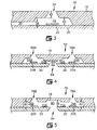
- Fig. 3 illustrates in cross-section through a supply channel 30, firing chamber 32 and nozzle hole 34, the configuration of a nozzle plate 36 which enables the design of the firing chamber 32 to be optimized independently of the supply channel 30.
- the height 38 of the supply channel 30 is substantially less than the height 40 of the firing chamber, preferably from about 0.2 to about 4.0 times the height 40 of the firing chamber 32.
- Fig. 4 illustrates an alternative nozzle plate design which combines the features of reduced supply channel height with a means for trapping debris so that debris does not enter and block the supply channels.
- the nozzle plate 50 as seen in cross section cutting through two ink supply channels 52A and 52B, two firing chambers 54A and 54B and two nozzle holes 56A and 56B, contains projections 60 in the ink supply region 62 which extend into the supply channels 52A and 52B a portion of the distance from the polymeric material 18 to the semiconductor substrate 20. Accordingly, as debris or other foreign matter enter the supply region 62 from the ink via 64 in the substrate 20, the projections 60 block the debris from entering the ink supply channels 52A and 52B.
- the design shown in Fig. 4 not only decouples the design of the firing chambers 54A and 54B from that of the nozzles holes 56A and 56B, but also acts to trap foreign matter before it enter and blocks the supply channels 52A and 52B.
- FIG. 5 is a cross sectional view of a nozzle plate 70 through two supply channels 72A and 72B, two firing chambers 74A and 74B and two nozzle holes 76A and 76B.
- the distance 78 between the polymeric material 18 and the semiconductor substrate 20 in the ink supply region 80 has been increased so that the ink supply region 80 has a height which is greater than the height of the ink supply channels 72A and 72B of the firing chambers 74A and 74B.
- the fluidic inertance in the ink supply region 80 is reduced thereby increasing the flow of ink from the ink via 84 to the ink supply channels 72A and 72B and firing chambers 74A and 74B.
- the period of time known as settling time, which must elapse between successive firing of the same firing chamber is reduced to less than about 150 microseconds, preferably about 50 to about 130 microseconds, most preferably about 80 to about 125 microseconds, including all ranges subsumed therein.
- the nozzle plate of Fig. 5 may also contain one or both of the features of the nozzle plates shown in Figs. 3 and 4 as described above. Accordingly, the height of the supply channels 72A and 72B may be less than height of the firing chambers 74A and 74B as shown in Fig. 3 and/or the polymeric material 18 may contain projections which extend into the supply channels 72A and 72B a portion of the distance from the polymeric material 18 to the semiconductor substrate 20.
- nozzle holes designs are illustrated in Figs. 6 and 7 and may be used with any of the foregoing nozzle plates.
- the nozzle hole 90 may have a substantially bell shaped configuration with the wider portion 92 of the hole 90 facing the firing chamber 94 so that there is a smooth transition from the firing chamber 94 to the exit 96 of the nozzle hole 90. Because the nozzle hole 90 does not have a sharp transition between the firing chamber 94 and the exit 96 of the hole 90, ink ejected from the nozzle hole has an improved flow pattern.
- the nozzle plate 100 contains nozzle holes 102 and firing chambers 104 which also do not have a sharp transition between the nozzle hole 102 and the firing chamber 104.
- the nozzle hole 102 and firing chamber 104 have a frustum conical shape for the entire distance 106 between the semiconductor substrate 20 and the exit 108 of the nozzle hole 102.
- the conical shape of the nozzle hole 102 and firing chamber 104 reduces the trapping of air in the firing chamber by eliminating the sharp boundary between the firing chamber 104 and nozzle hole 102.
- the shape also provides better ink flow in the chamber and out through the nozzle hole 102 by eliminating dead zones in the firing chamber 104 thereby decreasing the likelihood of air remaining in the firing chamber area.
- the conical shape also reduce air ingestion by increasing meniscus damping of the oscillations caused by bubble formation and vapor bubble collapse in the firing chamber 104.
- nozzle plates of the invention may include the use of a single mask or multiple masks and methods for controlling the laser radiation energy impacted on the polymeric material.
- a defocusing technique is preferably used.
- a polymeric material 110 to be ablated in the form of a film is unrolled from a supply reel 112 onto a platen 114.
- the platen 114 is movable in a vertical direction along an axis 116 of a laser beam 118 emitted from a laser source 120.
- a mask 122 containing the flow features to be formed in the polymeric material 110 is placed in the path of the laser beam 118 so that the features as described above are formed. After ablating the flow features in the polymeric material 110, the material is rewound on a product reel 124 for further processing.
- the laser beam is focused at a point which is plus or minus about 50 microns, preferably plus or minus about 30 microns and most preferably plus or minus about 10 microns within the top surface of the polymeric material 110.
- the platen is moved in a vertical direction toward the laser 120 along laser beam axis 118 in order to control the defocus of the beam 118.
- the wall angle of the nozzle holes formed in the polymeric material is gradually varied between smaller angles measured from the horizontal plane perpendicular to the laser beam axis 116 and larger hole diameters for large values of beam defocus to smaller hole diameters and larger angles measured from the horizontal plane perpendicular to the laser beam axis 116 for more focused laser beams.
- nozzle holes having bell shapes or frustum conical shapes or a combination of bell and/or conical shapes may be made.
- a laser which may be used to create flow features in the polymeric material to form the nozzle plates using the above described masks may be selected from an F 2 , ArF, KrCl, KrF, or XeCl excimer or a frequency multiplied YAG laser.
- Laser ablation of the polymeric material is achieved at a power of from about 100 millijoules per centimeter squared to about 5,000 millijoules per centimeter squared, preferably from about 150 to about 1,500 millijoules per centimeter squared, and most preferably from about 700 to about 900 millijoules per centimeter squared including all ranges subsumed therein.
- a laser beam having a wavelength of from about 150 nanometers to about 400 nanometers and most preferably from about 280 to about 330 nanometers is applied in pulses lasting from about one nanosecond to about 200 nanoseconds and most preferably about 20 nanoseconds.
- Specific flow features of the nozzle plate are formed by applying a predetermined number of pulses of the laser beam through the mask. Many energy pulses may be required in those portions of the polymeric material from which a greater cross-sectional depth of material is removed, such as the nozzles holes, and fewer energy pulses may be required in those portions of the polymeric material which require only a portion of the material be removed from the cross-sectional depth of the material, such as the firing chambers and ink supply channels.
- the platen can be fixed and the image plane produced by the imaging optics in the laser tool is varied in the vertical/Z-axis.
- the imaging optics in the laser tool is fixed, and the platen is moved in the vertical axis via a motor. Therefore, the relative motions of the platen and image plane will determine the features ablated in the polymeric material.
- the image plane was coplanar with the top surface of the polymeric material.
- the platen was moved up to shorten the distance between the laser and the polymeric material along the optical path. While there is no limitation, generally, with respect to the number of shots fired and the distance the platen is moved, a typical example often includes about 300 shots fired by the laser and platen movement of about 60 microns.
- the nozzle plates of this invention may be employed on any substrate capable of being used in an ink jet printer.
- the nozzle plates and substrates can result in an ink jet printhead capable of distributing ink to the firing chambers from the side or the center of the substrate.
- a single mask having a varying opacity from transparent to opaque may be used to reduce the manufacturing steps and time required to produce the nozzle plates.
- a particularly preferred mask is illustrated in Figs. 9 and 10.
- the mask 130 (of varying opacity) contains transparent regions 132 which are used to ablate more than one feature such as nozzle holes in a polymeric material. Surrounding the transparent regions are semi- transparent regions 134 which are used to produce the firing chambers in the nozzle plate.
- the supply channels are formed by semi-transparent regions 136 and the ink supply region is formed by semi-transparent region 138 which have either the same or more opacity than the firing chamber regions 134.
- the periphery 140 of the mask 130 around the flow features is substantially opaque so that little or no ablation of the polymeric material takes place outside of the firing chamber region 134, supply channel region 136 and ink supply region 138.
- the semi-transparent and opaque regions of the mask 130 may be made by varying the shading of the mask by increasing the number of opaque lines and thus the gray scale shading of the mask in the regions where lower opacity is desired. Any of the methods known to those of skill in the art may be used to prepare the mask have semi-transparent and opaque regions.
- the lines may be coated or printed onto the mask material or web made from metal or other material resistant to ablation by laser radiation.
- Masks are typically made of quartz or other materials capable of transmitting uv light including calcium fluoride, magnesium fluoride and glass.
- the opaque regions may be formed from any metal capable of absorbing and/or reflecting uv light at the requisite wavelength, or it can be formed from a dielectric such as a metal oxide.
- the side boundaries of the flow features ablated in the polymeric material are defined by the mask, which allows essentially full laser beam power to pass through holes or transparent regions of the mask and inhibits or reduces the laser beam energy reaching the polymeric material in the opaque and semi-transparent regions of the mask, respectively.
- the sacrificial layer is preferably a water soluble polymeric material, preferably polyvinyl alcohol, which may be removed by directing jets of water at the sacrificial layer until substantially all of the sacrificial layer has been removed from the adhesive layer. Since the sacrificial layer contains the debris, removal of the sacrificial will carry away the debris adhered to it. In this manner the polymeric material is freed of the debris which may cause structural or operational problems.
Landscapes
- Engineering & Computer Science (AREA)
- Manufacturing & Machinery (AREA)
- Physics & Mathematics (AREA)
- Optics & Photonics (AREA)
- Geometry (AREA)
- Particle Formation And Scattering Control In Inkjet Printers (AREA)
Applications Claiming Priority (2)
| Application Number | Priority Date | Filing Date | Title |
|---|---|---|---|
| US827242 | 1986-02-06 | ||
| US08/827,242 US6158843A (en) | 1997-03-28 | 1997-03-28 | Ink jet printer nozzle plates with ink filtering projections |
Publications (2)
| Publication Number | Publication Date |
|---|---|
| EP0867292A2 true EP0867292A2 (fr) | 1998-09-30 |
| EP0867292A3 EP0867292A3 (fr) | 1999-08-11 |
Family
ID=25248691
Family Applications (1)
| Application Number | Title | Priority Date | Filing Date |
|---|---|---|---|
| EP98302453A Withdrawn EP0867292A3 (fr) | 1997-03-28 | 1998-03-30 | Plaques à buses d'une imprimante à jet d'encre |
Country Status (6)
| Country | Link |
|---|---|
| US (1) | US6158843A (fr) |
| EP (1) | EP0867292A3 (fr) |
| JP (1) | JPH10291317A (fr) |
| KR (1) | KR100508193B1 (fr) |
| CN (1) | CN1103688C (fr) |
| TW (1) | TW367289B (fr) |
Cited By (6)
| Publication number | Priority date | Publication date | Assignee | Title |
|---|---|---|---|---|
| EP1153749A1 (fr) * | 2000-05-10 | 2001-11-14 | Hewlett-Packard Company | Système et méthode pour contrôler localement l'épaisseur d'une plaque à orifices flexible |
| WO2002098666A1 (fr) * | 2001-06-05 | 2002-12-12 | Xaar Technology Limited | Plaque a buses pour appareil de depot de gouttelettes |
| EP1380421A1 (fr) * | 2002-07-10 | 2004-01-14 | Canon Kabushiki Kaisha | Tête de décharge de liquide et méthode de fabrication corresspondante |
| EP1380424A1 (fr) * | 2002-07-10 | 2004-01-14 | Canon Kabushiki Kaisha | Méthode de fabrication d' une tête de decharge de liquide |
| EP1661708A1 (fr) * | 1999-12-27 | 2006-05-31 | Telecom Italia S.p.A. | Tête d'impression avec plusieurs canaux d'alimentation en encre |
| EP1437223B1 (fr) * | 2003-01-10 | 2009-10-07 | Canon Kabushiki Kaisha | Tête d'enregistrement à jet d'encre |
Families Citing this family (31)
| Publication number | Priority date | Publication date | Assignee | Title |
|---|---|---|---|---|
| SG52140A1 (en) | 1994-03-04 | 1998-09-28 | Canon Kk | Ink jet recording head and method of manufacture therefor and laser processing apparatus and ink jet recording apparatus |
| US6540335B2 (en) * | 1997-12-05 | 2003-04-01 | Canon Kabushiki Kaisha | Ink jet print head and ink jet printing device mounting this head |
| JP4532785B2 (ja) | 2001-07-11 | 2010-08-25 | キヤノン株式会社 | 構造体の製造方法、および液体吐出ヘッドの製造方法 |
| JP2003025577A (ja) | 2001-07-11 | 2003-01-29 | Canon Inc | 液体吐出ヘッド |
| JP2004042389A (ja) * | 2002-07-10 | 2004-02-12 | Canon Inc | 微細構造体の製造方法、液体吐出ヘッドの製造方法および液体吐出ヘッド |
| JP4280574B2 (ja) * | 2002-07-10 | 2009-06-17 | キヤノン株式会社 | 液体吐出ヘッドの製造方法 |
| JP3890268B2 (ja) * | 2002-07-10 | 2007-03-07 | キヤノン株式会社 | 液体吐出ヘッドおよび、該ヘッドの製造方法 |
| US6896360B2 (en) | 2002-10-31 | 2005-05-24 | Hewlett-Packard Development Company, L.P. | Barrier feature in fluid channel |
| US7364675B2 (en) * | 2002-11-05 | 2008-04-29 | The Ohio State University Research Foundation | Self-folding polymer microparticles |
| US6746106B1 (en) | 2003-01-30 | 2004-06-08 | Hewlett-Packard Development Company, L.P. | Fluid ejection device |
| US6902256B2 (en) * | 2003-07-16 | 2005-06-07 | Lexmark International, Inc. | Ink jet printheads |
| US7244014B2 (en) * | 2003-10-28 | 2007-07-17 | Lexmark International, Inc. | Micro-fluid ejection devices and method therefor |
| KR100590881B1 (ko) * | 2004-05-14 | 2006-06-19 | 삼성전자주식회사 | 광경화성 수지 조성물 및 그의 패터닝 방법 |
| US7357499B2 (en) * | 2004-05-25 | 2008-04-15 | Samsung Electronics Co., Ltd. | Inkjet print head with multi-functional structure |
| JP4761498B2 (ja) * | 2004-06-28 | 2011-08-31 | キヤノン株式会社 | 感光性樹脂組成物、ならびにこれを用いた段差パターンの製造方法及びインクジェットヘッドの製造方法 |
| EP1763706B1 (fr) | 2004-06-28 | 2013-12-11 | Canon Kabushiki Kaisha | Procede de fabrication de tete de decharge de liquide |
| US7165831B2 (en) | 2004-08-19 | 2007-01-23 | Lexmark International, Inc. | Micro-fluid ejection devices |
| US7370944B2 (en) * | 2004-08-30 | 2008-05-13 | Eastman Kodak Company | Liquid ejector having internal filters |
| KR100641358B1 (ko) * | 2004-09-23 | 2006-11-01 | 삼성전자주식회사 | 광경화성 수지 조성물을 사용한 잉크젯 프린트 헤드의제조방법 |
| US20060113285A1 (en) * | 2004-12-01 | 2006-06-01 | Lexmark International, Inc. | Methods of laser ablating polymeric materials to provide uniform laser ablated features therein |
| JP4459037B2 (ja) * | 2004-12-01 | 2010-04-28 | キヤノン株式会社 | 液体吐出ヘッド |
| US7763015B2 (en) | 2005-01-24 | 2010-07-27 | Intuitive Surgical Operations, Inc. | Modular manipulator support for robotic surgery |
| ATE541702T1 (de) * | 2005-03-31 | 2012-02-15 | Telecom Italia Spa | Tintenstrahldruckkopf ohne ansammlung von blasen |
| JP5008849B2 (ja) * | 2005-09-08 | 2012-08-22 | ソニーモバイルディスプレイ株式会社 | レーザ加工方法及び透明樹脂層を有する表示装置の製造方法 |
| JP4819586B2 (ja) * | 2006-06-14 | 2011-11-24 | 富士フイルム株式会社 | 液体吐出機構および画像形成装置 |
| JP2009233955A (ja) * | 2008-03-26 | 2009-10-15 | Canon Inc | 微細構造体の製造方法及び液体吐出ヘッドの製造方法 |
| US8328330B2 (en) * | 2008-06-03 | 2012-12-11 | Lexmark International, Inc. | Nozzle plate for improved post-bonding symmetry |
| JP5069186B2 (ja) * | 2008-07-29 | 2012-11-07 | ソニー株式会社 | 液滴吐出ヘッド及び液滴吐出装置 |
| JP5426333B2 (ja) * | 2009-11-24 | 2014-02-26 | 信越化学工業株式会社 | 中空の構造体製造方法 |
| JP6202869B2 (ja) * | 2013-04-17 | 2017-09-27 | キヤノン株式会社 | 液体吐出ヘッド |
| JP2017061102A (ja) * | 2015-09-25 | 2017-03-30 | キヤノン株式会社 | 液体吐出ヘッドおよびインクジェット記録装置 |
Family Cites Families (62)
| Publication number | Priority date | Publication date | Assignee | Title |
|---|---|---|---|---|
| US3549733A (en) * | 1968-12-04 | 1970-12-22 | Du Pont | Method of producing polymeric printing plates |
| US4044222A (en) * | 1976-01-16 | 1977-08-23 | Western Electric Company, Inc. | Method of forming tapered apertures in thin films with an energy beam |
| US4164745A (en) * | 1978-05-08 | 1979-08-14 | Northern Telecom Limited | Printing by modulation of ink viscosity |
| US4216477A (en) * | 1978-05-10 | 1980-08-05 | Hitachi, Ltd. | Nozzle head of an ink-jet printing apparatus with built-in fluid diodes |
| US4258468A (en) * | 1978-12-14 | 1981-03-31 | Western Electric Company, Inc. | Forming vias through multilayer circuit boards |
| US4317124A (en) * | 1979-02-14 | 1982-02-23 | Canon Kabushiki Kaisha | Ink jet recording apparatus |
| US4426253A (en) * | 1981-12-03 | 1984-01-17 | E. I. Du Pont De Nemours & Co. | High speed etching of polyimide film |
| US4568632A (en) * | 1982-10-07 | 1986-02-04 | International Business Machines Corporation | Patterning of polyimide films with far ultraviolet light |
| US4587534A (en) * | 1983-01-28 | 1986-05-06 | Canon Kabushiki Kaisha | Liquid injection recording apparatus |
| US4472238A (en) * | 1983-12-05 | 1984-09-18 | E. I. Du Pont De Nemours And Company | Process using plasma for forming conductive through-holes through a dielectric layer |
| US4508749A (en) * | 1983-12-27 | 1985-04-02 | International Business Machines Corporation | Patterning of polyimide films with ultraviolet light |
| US4635358A (en) * | 1985-01-03 | 1987-01-13 | E. I. Du Pont De Nemours And Company | Method for forming electrically conductive paths through a dielectric layer |
| US4642160A (en) * | 1985-08-12 | 1987-02-10 | Interconnect Technology Inc. | Multilayer circuit board manufacturing |
| US4746935A (en) * | 1985-11-22 | 1988-05-24 | Hewlett-Packard Company | Multitone ink jet printer and method of operation |
| US4683481A (en) * | 1985-12-06 | 1987-07-28 | Hewlett-Packard Company | Thermal ink jet common-slotted ink feed printhead |
| JPS62216259A (ja) * | 1986-03-17 | 1987-09-22 | Fujitsu Ltd | 混成集積回路の製造方法および構造 |
| US4714516A (en) * | 1986-09-26 | 1987-12-22 | General Electric Company | Method to produce via holes in polymer dielectrics for multiple electronic circuit chip packaging |
| US5061840A (en) * | 1986-10-14 | 1991-10-29 | Allergan, Inc. | Manufacture of ophthalmic lenses by excimer laser |
| CA1303904C (fr) * | 1987-08-10 | 1992-06-23 | Winthrop D. Childers | Formation de gouttelettes au moyen d'une buse decalee |
| GB8722085D0 (en) * | 1987-09-19 | 1987-10-28 | Cambridge Consultants | Ink jet nozzle manufacture |
| US4882595A (en) * | 1987-10-30 | 1989-11-21 | Hewlett-Packard Company | Hydraulically tuned channel architecture |
| US4829319A (en) * | 1987-11-13 | 1989-05-09 | Hewlett-Packard Company | Plastic orifice plate for an ink jet printhead and method of manufacture |
| US4959199A (en) * | 1988-02-19 | 1990-09-25 | Brewer Charles A | Autoclavable modular cassette and tray for holding dental instruments |
| US5208604A (en) * | 1988-10-31 | 1993-05-04 | Canon Kabushiki Kaisha | Ink jet head and manufacturing method thereof, and ink jet apparatus with ink jet head |
| DE3900961C1 (fr) * | 1988-12-23 | 1990-01-18 | Martin & Pagenstecher Gmbh, 5000 Koeln, De | |
| US4894115A (en) * | 1989-02-14 | 1990-01-16 | General Electric Company | Laser beam scanning method for forming via holes in polymer materials |
| JP2752686B2 (ja) * | 1989-03-24 | 1998-05-18 | キヤノン株式会社 | 液体噴射記録ヘッドの製造方法 |
| US5063280A (en) * | 1989-07-24 | 1991-11-05 | Canon Kabushiki Kaisha | Method and apparatus for forming holes into printed circuit board |
| US4940881A (en) * | 1989-09-28 | 1990-07-10 | Tamarack Scientific Co., Inc. | Method and apparatus for effecting selective ablation of a coating from a substrate, and controlling the wall angle of coating edge portions |
| JPH03169559A (ja) * | 1989-11-28 | 1991-07-23 | Seiko Epson Corp | インクジェットヘッドの製造方法 |
| JP2956206B2 (ja) * | 1989-12-05 | 1999-10-04 | セイコーエプソン株式会社 | インクジェット記録ヘッド用基板の製造方法 |
| JP2867602B2 (ja) * | 1990-05-08 | 1999-03-08 | セイコーエプソン株式会社 | プレートの接合方法およびインクジェットヘッドの製造方法 |
| US5119116A (en) * | 1990-07-31 | 1992-06-02 | Xerox Corporation | Thermal ink jet channel with non-wetting walls and a step structure |
| US5305015A (en) * | 1990-08-16 | 1994-04-19 | Hewlett-Packard Company | Laser ablated nozzle member for inkjet printhead |
| DE69111936T2 (de) * | 1990-08-16 | 1996-04-11 | Hewlett Packard Co | Photo-ablatierte Bauteile für Farbstrahldruckkopf. |
| US5291226A (en) * | 1990-08-16 | 1994-03-01 | Hewlett-Packard Company | Nozzle member including ink flow channels |
| JPH04107149A (ja) * | 1990-08-28 | 1992-04-08 | Seiko Epson Corp | ノズルの製造方法 |
| JP2940121B2 (ja) * | 1990-09-25 | 1999-08-25 | セイコーエプソン株式会社 | インクジェット記録ヘッド用基板の製造方法 |
| US5229785A (en) * | 1990-11-08 | 1993-07-20 | Hewlett-Packard Company | Method of manufacture of a thermal inkjet thin film printhead having a plastic orifice plate |
| JP3104070B2 (ja) * | 1990-11-09 | 2000-10-30 | セイコーエプソン株式会社 | インクジェット記録ヘッド |
| JP2946754B2 (ja) * | 1990-12-18 | 1999-09-06 | セイコーエプソン株式会社 | インクジェット記録ヘッドの製造方法 |
| JPH04235048A (ja) * | 1991-01-09 | 1992-08-24 | Seiko Epson Corp | インクジェットヘッド |
| JP3095795B2 (ja) * | 1991-01-18 | 2000-10-10 | キヤノン株式会社 | インクジェット記録ヘッドおよび該ヘッドの製造方法 |
| GB9105870D0 (en) * | 1991-03-20 | 1991-05-08 | Xaar Ltd | Fluid cooled contact mask |
| US5198834A (en) * | 1991-04-02 | 1993-03-30 | Hewlett-Packard Company | Ink jet print head having two cured photoimaged barrier layers |
| GB9202434D0 (en) * | 1992-02-05 | 1992-03-18 | Xaar Ltd | Method of and apparatus for forming nozzles |
| US5467118A (en) * | 1993-12-21 | 1995-11-14 | Hewlett-Packard Company | Ink cartridge for a hard copy printing or plotting apparatus |
| US5506608A (en) * | 1992-04-02 | 1996-04-09 | Hewlett-Packard Company | Print cartridge body and nozzle member having similar coefficient of thermal expansion |
| US5467115A (en) * | 1992-04-02 | 1995-11-14 | Hewlett-Packard Company | Inkjet printhead formed to eliminate ink trajectory errors |
| JP3196796B2 (ja) * | 1992-06-24 | 2001-08-06 | セイコーエプソン株式会社 | インクジェット記録ヘッドのノズル形成方法 |
| JPH06183008A (ja) * | 1992-12-19 | 1994-07-05 | Fuji Xerox Co Ltd | サーマルインクジェット記録ヘッド及びその製造方法 |
| US5387314A (en) * | 1993-01-25 | 1995-02-07 | Hewlett-Packard Company | Fabrication of ink fill slots in thermal ink-jet printheads utilizing chemical micromachining |
| US5378137A (en) * | 1993-05-10 | 1995-01-03 | Hewlett-Packard Company | Mask design for forming tapered inkjet nozzles |
| US5463413A (en) * | 1993-06-03 | 1995-10-31 | Hewlett-Packard Company | Internal support for top-shooter thermal ink-jet printhead |
| US5484507A (en) * | 1993-12-01 | 1996-01-16 | Ford Motor Company | Self compensating process for aligning an aperture with crystal planes in a substrate |
| JPH07195697A (ja) * | 1993-12-30 | 1995-08-01 | Canon Inc | インクジェット記録ヘッド,インクジェット記録方法およびインクジェット記録装置 |
| US5495665A (en) * | 1994-11-04 | 1996-03-05 | International Business Machines Corporation | Process for providing a landless via connection |
| JP3082652B2 (ja) * | 1994-12-27 | 2000-08-28 | キヤノン株式会社 | 照明装置及びそれを用いたデバイスの製造方法 |
| EP0761448B1 (fr) * | 1995-08-28 | 2002-11-27 | Lexmark International, Inc. | Procédé de formation d'une structure de buses pour tête d'impression à jet d'encre |
| US5818478A (en) * | 1996-08-02 | 1998-10-06 | Lexmark International, Inc. | Ink jet nozzle placement correction |
| US5907333A (en) * | 1997-03-28 | 1999-05-25 | Lexmark International, Inc. | Ink jet print head containing a radiation curable resin layer |
| US6045214A (en) * | 1997-03-28 | 2000-04-04 | Lexmark International, Inc. | Ink jet printer nozzle plate having improved flow feature design and method of making nozzle plates |
-
1997
- 1997-03-28 US US08/827,242 patent/US6158843A/en not_active Expired - Lifetime
-
1998
- 1998-03-27 CN CN98108080A patent/CN1103688C/zh not_active Expired - Fee Related
- 1998-03-28 KR KR10-1998-0010852A patent/KR100508193B1/ko not_active Expired - Fee Related
- 1998-03-30 EP EP98302453A patent/EP0867292A3/fr not_active Withdrawn
- 1998-03-30 JP JP10123833A patent/JPH10291317A/ja active Pending
- 1998-04-08 TW TW087104675A patent/TW367289B/zh not_active IP Right Cessation
Cited By (12)
| Publication number | Priority date | Publication date | Assignee | Title |
|---|---|---|---|---|
| EP1661708A1 (fr) * | 1999-12-27 | 2006-05-31 | Telecom Italia S.p.A. | Tête d'impression avec plusieurs canaux d'alimentation en encre |
| EP1153749A1 (fr) * | 2000-05-10 | 2001-11-14 | Hewlett-Packard Company | Système et méthode pour contrôler localement l'épaisseur d'une plaque à orifices flexible |
| US6467878B1 (en) | 2000-05-10 | 2002-10-22 | Hewlett-Packard Company | System and method for locally controlling the thickness of a flexible nozzle member |
| WO2002098666A1 (fr) * | 2001-06-05 | 2002-12-12 | Xaar Technology Limited | Plaque a buses pour appareil de depot de gouttelettes |
| EP1380421A1 (fr) * | 2002-07-10 | 2004-01-14 | Canon Kabushiki Kaisha | Tête de décharge de liquide et méthode de fabrication corresspondante |
| EP1380424A1 (fr) * | 2002-07-10 | 2004-01-14 | Canon Kabushiki Kaisha | Méthode de fabrication d' une tête de decharge de liquide |
| US6942321B2 (en) | 2002-07-10 | 2005-09-13 | Canon Kabushiki Kaisha | Method for producing liquid discharge head |
| US7048358B2 (en) | 2002-07-10 | 2006-05-23 | Canon Kabushiki Kaisha | Liquid discharge head and method for manufacturing such head |
| US7293859B2 (en) | 2002-07-10 | 2007-11-13 | Canon Kabushiki Kaisha | Liquid discharge head and method for manufacturing such head |
| EP1437223B1 (fr) * | 2003-01-10 | 2009-10-07 | Canon Kabushiki Kaisha | Tête d'enregistrement à jet d'encre |
| US7628472B2 (en) | 2003-01-10 | 2009-12-08 | Canon Kabushiki Kaisha | Ink-jet recording head |
| US8083322B2 (en) | 2003-01-10 | 2011-12-27 | Canon Kabushiki Kaisha | Ink-jet recording head |
Also Published As
| Publication number | Publication date |
|---|---|
| CN1196298A (zh) | 1998-10-21 |
| KR19980080812A (ko) | 1998-11-25 |
| EP0867292A3 (fr) | 1999-08-11 |
| CN1103688C (zh) | 2003-03-26 |
| TW367289B (en) | 1999-08-21 |
| JPH10291317A (ja) | 1998-11-04 |
| KR100508193B1 (ko) | 2005-11-03 |
| US6158843A (en) | 2000-12-12 |
Similar Documents
| Publication | Publication Date | Title |
|---|---|---|
| US6158843A (en) | Ink jet printer nozzle plates with ink filtering projections | |
| US6283584B1 (en) | Ink jet flow distribution system for ink jet printer | |
| EP0471157B1 (fr) | Composants obtenus par photo-ablation pour tête d'impression à jet d'encre | |
| KR100463464B1 (ko) | 노즐판을프린트헤드에대해싱귤레이팅및부착하는방법 | |
| JP3957851B2 (ja) | 液体吐出方法 | |
| KR100512660B1 (ko) | 노즐판,노즐판을포함하는잉크젯프린트헤드,및유동기구설계를구비한잉크젯프린터용노즐판을제조하기위한방법 | |
| EP1503901B1 (fr) | Appareil et procede faisant intervenir une caracteristique de surface | |
| EP1024008B1 (fr) | Tête à éjection de liquide, méthode pour prévenir une défaillance d'éjection accidentelle de la tête, et procédé de fabrication de cette tête | |
| EP0594110B1 (fr) | Tête d'impression par jet d'encre, sa méthode de fabrication et appareil à jet d'encre l'utilisant | |
| EP0810095B1 (fr) | Structure d'une cartouche d'impression à jet d'encre conçue pour diminuer la déformation de la tête d'impression lors du scellage par adhésif de cette tête sur la cartouche d'impression | |
| EP0997284B1 (fr) | Têtes d'impression | |
| EP0564120A2 (fr) | Elément à buse comprenant des canaux d'écoulement de l'encre | |
| EP0564101A2 (fr) | Elément à buse ablaté au laser pour une tête d'imprimante à jet d'encre | |
| JPH01108056A (ja) | インクジェットプリンタ用ノズル | |
| EP0761448A2 (fr) | Procédé de formation d'une structure de buses pour tête d'impression à jet d'encre | |
| EP1016525B1 (fr) | Tête à jet de liquide, méthode d'ejection de liquide et appareil d'impression à jet de liquide | |
| CA2572092A1 (fr) | Structure a buse de jet de microfluide a structure reduite | |
| JP2001158099A (ja) | インクジェット記録ヘッド及びインクジェット記録装置 | |
| JP2766035B2 (ja) | インクジェット記録方法 | |
| JP4177544B2 (ja) | プリントヘッド及びその製造方法並びにこのヘッドに使用するオリフィスプレート及びその製造方法 | |
| JPH07137262A (ja) | インクジェット記録ヘッドおよびインクジェット記録装置 | |
| JPH07156403A (ja) | インクジェット記録ヘッド及び製造方法 | |
| JP2001150686A (ja) | インクジェットプリンタヘッド製造方法 | |
| JPH0343254A (ja) | 熱インクジェットの印字ヘッド | |
| JPH09174858A (ja) | インクジェットヘッドの製造方法 |
Legal Events
| Date | Code | Title | Description |
|---|---|---|---|
| PUAI | Public reference made under article 153(3) epc to a published international application that has entered the european phase |
Free format text: ORIGINAL CODE: 0009012 |
|
| AK | Designated contracting states |
Kind code of ref document: A2 Designated state(s): DE FR GB |
|
| AX | Request for extension of the european patent |
Free format text: AL;LT;LV;MK;RO;SI |
|
| PUAL | Search report despatched |
Free format text: ORIGINAL CODE: 0009013 |
|
| AK | Designated contracting states |
Kind code of ref document: A3 Designated state(s): AT BE CH DE DK ES FI FR GB GR IE IT LI LU MC NL PT SE |
|
| AX | Request for extension of the european patent |
Free format text: AL;LT;LV;MK;RO;SI |
|
| 17P | Request for examination filed |
Effective date: 19991117 |
|
| AKX | Designation fees paid |
Free format text: DE FR GB |
|
| 17Q | First examination report despatched |
Effective date: 20010111 |
|
| STAA | Information on the status of an ep patent application or granted ep patent |
Free format text: STATUS: THE APPLICATION IS DEEMED TO BE WITHDRAWN |
|
| 18D | Application deemed to be withdrawn |
Effective date: 20020503 |