EP0867352A1 - Verfahren zur automatischen steuerung von fahrzeugen während der fahrt - Google Patents
Verfahren zur automatischen steuerung von fahrzeugen während der fahrt Download PDFInfo
- Publication number
- EP0867352A1 EP0867352A1 EP97943128A EP97943128A EP0867352A1 EP 0867352 A1 EP0867352 A1 EP 0867352A1 EP 97943128 A EP97943128 A EP 97943128A EP 97943128 A EP97943128 A EP 97943128A EP 0867352 A1 EP0867352 A1 EP 0867352A1
- Authority
- EP
- European Patent Office
- Prior art keywords
- vehicle
- running
- moving target
- section
- control section
- Prior art date
- Legal status (The legal status is an assumption and is not a legal conclusion. Google has not performed a legal analysis and makes no representation as to the accuracy of the status listed.)
- Granted
Links
Images
Classifications
-
- G—PHYSICS
- G08—SIGNALLING
- G08G—TRAFFIC CONTROL SYSTEMS
- G08G1/00—Traffic control systems for road vehicles
- G08G1/07—Controlling traffic signals
- G08G1/075—Ramp control
-
- B—PERFORMING OPERATIONS; TRANSPORTING
- B61—RAILWAYS
- B61L—GUIDING RAILWAY TRAFFIC; ENSURING THE SAFETY OF RAILWAY TRAFFIC
- B61L23/00—Control, warning or like safety means along the route or between vehicles or trains
- B61L23/34—Control, warning or like safety means along the route or between vehicles or trains for indicating the distance between vehicles or trains by the transmission of signals therebetween
-
- B—PERFORMING OPERATIONS; TRANSPORTING
- B61—RAILWAYS
- B61L—GUIDING RAILWAY TRAFFIC; ENSURING THE SAFETY OF RAILWAY TRAFFIC
- B61L27/00—Central railway traffic control systems; Trackside control; Communication systems specially adapted therefor
-
- B—PERFORMING OPERATIONS; TRANSPORTING
- B61—RAILWAYS
- B61L—GUIDING RAILWAY TRAFFIC; ENSURING THE SAFETY OF RAILWAY TRAFFIC
- B61L99/00—Subject matter not provided for in other groups of this subclass
- B61L99/002—Autonomous vehicles, i.e. under distributed traffic control
Definitions
- the present invention relates to a method for automatically controlling the running of vehicles.
- the method for automatically controlling the running of vehicles on a road is generally classified into a "moving target” method (hereinafter referred to as an MT method) and a vehicle-to-vehicle distance method.
- a moving target method hereinafter referred to as an MT method
- a vehicle-to-vehicle distance method hereinafter referred to as an MT method
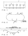
- the MT method comprises controlling the running of a real vehicle on a real running road so as to follow an imaginary target (moving target) running an imaginary running road on a computer. That is, the MT method as shown in FIG. 1 assumes a running road 1, on the computer, equivalent to a real road and comprises setting points, that is, MTs 2, for enabling an ideal running to be achieved at a given interval on the running road 1 and running them and making control for enabling a real vehicle on the real road to follow the MT 2.
- FIG. 2 is an enlarged view showing the platform 6 and branch lane 7.
- reference numeral 8 represents a branching point and 9 a merging point and 8a a decelerating lane constituting a lane from the branching point 8 to the platform 6 and 9a an accelerating lane from the platform 6 to the merging point 9.
- position information equipments 10 and communications equipments are provided along the main lane 5 over a full length to communicate with the vehicles and the vehicle is operated in accordance with a target signal issued from the position information equipment 10.
- control is made to enable the vehicle to depart from the platform 6 just in a timing to acquire the target MT 2 at the merging point 9 or all the MTs 2 which are allocated to respective vehicles to be delayed.
- the target MT 2 is generated at a given interval and the vehicle is controlled to enable the vehicle to follow the target M2.
- the MT control method above constitutes a positive control method, but it is necessary to provide the position information equipment and communications equipment over the full length of the running road. Therefore, a larger-sized computer system is required to control this.
- a vehicle-to-vehicle distance control method comprises mounting a vehicle-to-vehicle distance measuring device on each vehicle and operating the vehicle, while maintaining a proper distance between the vehicles, so that any collision may be prevented from occurring.
- This system has been extremely high in performance in a recent advance in the laser technique and in electronic technique.
- the system above has only to be equipped with a measuring device for each vehicle and any equipments as in the MT method need not be provided over the full length of the road, so that an economic advantage can be gained in view of a long distance to be covered.
- the conventional MT method presents the following problems because the target MT is generated at a given interval irrespective of any entry of the vehicle.
- the present invention provides a method for controlling the automatic runnings of a plurality of vehicles on a running road comprising main and branching lanes, characterizing in that
- a method for controlling the automatic runnings of a plurality of vehicles on a running road comprising main and branching lanes, characterizing in that
- a method for controlling the automatic runnings of a plurality of vehicles on a running road comprising main and branching lanes, characterizing in that
- the computer for making the operation control of the vehicle controls the vehicle on the running control section alone by the moving target method and it is possible to make the computer smaller in size and greatly lower in cost.
- the moving target is generated in a timing to be matched to the entering or joining of the vehicle onto the running control section. By doing so, there is no need for such a time and decelerating distance as to match the entry of the vehicle to the moving target. Further, it is possible to avoid any vehicle control disturbance by the moving target method at the entry of the running control section.
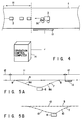
- FIGS. 4, 5A and 5B are schematic views sowing a major section of a vehicle running control method according to one aspect of the present invention.
- an MT control section 11 and vehicle-to-vehicle distance control section 12 are provided on a running road 1 along a rail.
- the running road 1 includes branching lanes 7, branched at a proper interval from a main lane 5, leading to a platform 6, such as a station, where passengers gets on or get off the vehicle.
- the branching lane 7 again merges past the platform 6 onto the main lane 5.
- a decelerating lane 8a ranges from the branching point 8 between the main lane 5 and the branching lane 7 to the platform 6 and an accelerating lane 9a from the platform 6 to a merging point 9 for merging onto the main lane 5.
- the MT control section 11 is defined to be a platform setting section including the branching point 8 between the main lane 5 and branching lane 7 and the merging line 9.
- the vehicle-to-vehicle distance control section 12 is defined to be the remaining section, that is, a section not including the platform 6.
- communications equipment and position information equipment 10 are provided at a given interval along the main and branching lanes 5 and 7 as shown in FIG. 5B to communicate with the vehicle.
- a vehicle detector 13 is mounted in front of an entry to detect the position, speed, course, etc., of the running vehicle 3 and inputs them to an operation control computer 14.
- the operation control computer 14 controls the generation of the MT and the operation of the running vehicle 3 in the MT control section 11 on the basis of the input information, etc., from the vehicle detector 13.
- the respective vehicle 3 is equipped with a computer and stores, in the computer, the information of whether it be run on the main lane or branched when it is run through the MT control section 11.
- the respective vehicle has its own vehicle number set thereon.
- a distance measuring device 3a such as a laser radar, is mounted on the vehicle 3 to measure a distance to an adjacent vehicle running in front of the vehicle 3.
- a distance measuring device 3a such as a laser radar
- the vehicle-to-vehicle distance control system is adopted on the vehicle-to-vehicle distance section 12 other than the MT control section 11.
- the vehicle 3 running on the vehicle-to-vehicle distance control section 12 is equipped with the distance measuring device 3a so as to measure the distance to a running vehicle in front and it can be run based on the measured distance information while properly maintaining their relative running distance. And when the vehicle 3 enters from the vehicle-to-vehicle distance control section 12 into the MT control section 11, the running position, speed, course, etc., are detected by the vehicle detector 13 and the detection information is sent to the operation control computer 14.
- the operation control computer 14, after the entry of the vehicle into the MT control section 11, can know, based on the detection information, whether the vehicle 3 is to be moved toward the branching lane 7 or to be moved straight on the main lane 5. In the case where the vehicle is running straight on the main lane 5, the operation control computer 14 can readily predict a timing in which it reaches the merging point 9.
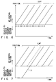
- the operation control computer 14 generates a target MT 2 at a given interval at abnormal time as shown in FIG. 6 and, when the vehicle 3 enters into the MT control section 11, a target MT 2 is generated, as shown in FIG. 7, in a timing in which the vehicle 3 enters there.
- the target MT 2 is generated in the timing to be matched to the entry of the vehicle 3. Thereafter, another target MT 2 is generated at a given interval again as in a normal time.
- the operation control computer 14 effects the operation control of the respective vehicles based on the position information of the running vehicles sequentially sent from the position information equipment 10.
- the generation interval of the target MT 2 is temporarily shifted so as to be matched to the entry of the vehicle 3. By doing so, it is possible to operate the vehicle 3 regularly without being decelerated.
- joining is achieved at a merging point 9 between the merging MT on the main lane 5 and the to-be-merged MT on the accelerating lane and, if, however, the timing is shifted between the merging MT and the to-be-merged MT, the generation of the merging MT is temporarily shifted so as to secure a matching between both.
- the main lane is a single lane and each vehicle 3 after advancing from the MT control section 11 to the vehicle-to-vehicle distance control section 12 measures a distance by the distance measuring device to the forwardly moving vehicle and advances toward the next MT control section 11 while effecting the vehicle-to-vehicle distance control.
- running control is made by the MT method on the running section, on which the vehicle runs past the branching and merging sites, and by the vehicle-to-vehicle distance control method on the remaining section. Therefore, it is only necessary to provide the position information equipment only on the running section including the branching and merging sites. Further, the operation control computer controls the MT control section alone, so that the system can be made compact and largely lower in cost.
- the target MT is generated in a timing in which the vehicle runs onto the entry site or merging site. As a result, it is not necessary to prepare a time and decelerating distance taken for the entering vehicle to secure a matching to the MT. It is also possible to avoid any vehicle control disturbance at the entry of the MT control section.
- the present invention relates to a method for automatically controlling the runnings of a plurality of vehicles on the road and is of utility to a long distance non-attended transportation system.
Landscapes
- Engineering & Computer Science (AREA)
- Mechanical Engineering (AREA)
- Physics & Mathematics (AREA)
- General Physics & Mathematics (AREA)
- Traffic Control Systems (AREA)
- Train Traffic Observation, Control, And Security (AREA)
- Control Of Driving Devices And Active Controlling Of Vehicle (AREA)
- Control Of Position, Course, Altitude, Or Attitude Of Moving Bodies (AREA)
Applications Claiming Priority (4)
| Application Number | Priority Date | Filing Date | Title |
|---|---|---|---|
| JP261893/96 | 1996-10-02 | ||
| JP26189396A JP3268213B2 (ja) | 1996-10-02 | 1996-10-02 | 走行車両制御方法 |
| JP26189396 | 1996-10-02 | ||
| PCT/JP1997/003496 WO1998014359A1 (fr) | 1996-10-02 | 1997-10-01 | Procede de commande automatique de la translation d'un vehicule |
Publications (3)
| Publication Number | Publication Date |
|---|---|
| EP0867352A1 true EP0867352A1 (de) | 1998-09-30 |
| EP0867352A4 EP0867352A4 (de) | 1999-06-30 |
| EP0867352B1 EP0867352B1 (de) | 2003-01-02 |
Family
ID=17368234
Family Applications (1)
| Application Number | Title | Priority Date | Filing Date |
|---|---|---|---|
| EP97943128A Expired - Lifetime EP0867352B1 (de) | 1996-10-02 | 1997-10-01 | Verfahren zur automatischen steuerung von fahrzeugen während der fahrt |
Country Status (5)
| Country | Link |
|---|---|
| US (1) | US6138064A (de) |
| EP (1) | EP0867352B1 (de) |
| JP (1) | JP3268213B2 (de) |
| DE (1) | DE69718139T2 (de) |
| WO (1) | WO1998014359A1 (de) |
Cited By (3)
| Publication number | Priority date | Publication date | Assignee | Title |
|---|---|---|---|---|
| EP0898257A1 (de) * | 1997-08-22 | 1999-02-24 | Mitsubishi Heavy Industries, Ltd. | Steuerungsverfahren für fahrendes Kraftfahrzeug |
| RU2265541C2 (ru) * | 2003-03-24 | 2005-12-10 | Самарская государственная академия путей сообщения (СамГАПС) | Релейно-компьютерная централизация |
| CN111204278A (zh) * | 2020-01-22 | 2020-05-29 | 长安大学 | 一种大型货车速度失控预警方法 |
Families Citing this family (13)
| Publication number | Priority date | Publication date | Assignee | Title |
|---|---|---|---|---|
| JP2000311291A (ja) * | 1999-04-27 | 2000-11-07 | Honda Motor Co Ltd | 隊列走行制御装置 |
| US6314341B1 (en) * | 1999-11-26 | 2001-11-06 | Yutaka John Kanayama | Method of recording trajectory data and sensor data for a manually-driven vehicle |
| US7593838B2 (en) * | 2000-03-28 | 2009-09-22 | Robert Bosch Gmbh | Model-supported allocation of vehicles to traffic lanes |
| US8538692B2 (en) | 2006-06-19 | 2013-09-17 | Amazon Technologies, Inc. | System and method for generating a path for a mobile drive unit |
| US8220710B2 (en) | 2006-06-19 | 2012-07-17 | Kiva Systems, Inc. | System and method for positioning a mobile drive unit |
| US20130302132A1 (en) | 2012-05-14 | 2013-11-14 | Kiva Systems, Inc. | System and Method for Maneuvering a Mobile Drive Unit |
| US7873469B2 (en) * | 2006-06-19 | 2011-01-18 | Kiva Systems, Inc. | System and method for managing mobile drive units |
| US8649899B2 (en) | 2006-06-19 | 2014-02-11 | Amazon Technologies, Inc. | System and method for maneuvering a mobile drive unit |
| US7920962B2 (en) | 2006-06-19 | 2011-04-05 | Kiva Systems, Inc. | System and method for coordinating movement of mobile drive units |
| US7912574B2 (en) | 2006-06-19 | 2011-03-22 | Kiva Systems, Inc. | System and method for transporting inventory items |
| PT2319742E (pt) * | 2009-10-30 | 2012-08-03 | Siemens Ag | Disposição e método para o controlo de uma propulsão de um meio de transporte sem condutor |
| US8892240B1 (en) | 2011-06-29 | 2014-11-18 | Amazon Technologies, Inc. | Modular material handling system for order fulfillment |
| CN109661630B (zh) * | 2016-09-12 | 2023-04-18 | 索尤若驱动有限及两合公司 | 用于位置探测的方法和系统 |
Family Cites Families (20)
| Publication number | Priority date | Publication date | Assignee | Title |
|---|---|---|---|---|
| NL7309661A (de) * | 1972-08-01 | 1974-02-05 | ||
| JPS5030496A (de) * | 1973-07-17 | 1975-03-26 | ||
| JPS5467905A (en) * | 1977-11-10 | 1979-05-31 | Nippon Steel Corp | Operation controller |
| JPS5472806A (en) * | 1977-11-21 | 1979-06-11 | Nippon Steel Corp | Travel control device |
| JPS5488607A (en) * | 1977-12-26 | 1979-07-13 | Teihachi Fujita | Device for supporting leader for stake driver |
| JPS5493506A (en) * | 1977-12-28 | 1979-07-24 | Fujitsu Ltd | Station approach control method |
| JPS5695766A (en) * | 1979-12-27 | 1981-08-03 | Tokyo Shibaura Electric Co | Controlling system for driving of car |
| JPS56123702A (en) * | 1980-03-05 | 1981-09-29 | Hitachi Ltd | Impact preventing device for rolling stock vehicle |
| US5297049A (en) * | 1982-11-08 | 1994-03-22 | Hailemichael Gurmu | Vehicle guidance system |
| US5179329A (en) * | 1989-04-25 | 1993-01-12 | Shinko Electric Co., Ltd. | Travel control method, travel control device, and mobile robot for mobile robot systems |
| US4965583A (en) * | 1989-05-02 | 1990-10-23 | Charles Broxmeyer | Collision avoidance system for automatically controlled vehicles moving at short headways |
| CA2053028C (en) * | 1990-10-23 | 1996-04-09 | Hideichi Tanizawa | Carriage running control system |
| US5331561A (en) * | 1992-04-23 | 1994-07-19 | Alliant Techsystems Inc. | Active cross path position correlation device |
| US5369591A (en) * | 1993-03-11 | 1994-11-29 | Broxmeyer; Charles | Vehicle longitudinal control and collision avoidance system for an automated highway system |
| GB2299064A (en) * | 1993-11-16 | 1996-09-25 | Francis Cyril Perrott | Improvements in or relating to transportation |
| IL108549A (en) * | 1994-02-03 | 1998-08-16 | Zelinkovsky Reuven | Transport system |
| JP3087606B2 (ja) * | 1995-05-11 | 2000-09-11 | 株式会社日立製作所 | 自動車用車間距離計測装置及び方法 |
| JP3633707B2 (ja) * | 1996-03-08 | 2005-03-30 | 日産ディーゼル工業株式会社 | 車群走行制御装置 |
| DE19637245C2 (de) * | 1996-09-13 | 2000-02-24 | Bosch Gmbh Robert | Verfahren und Vorrichtung zur Regelung der Geschwindigkeit eines Fahrzeugs |
| US5936517A (en) * | 1998-07-03 | 1999-08-10 | Yeh; Show-Way | System to minimize the distance between trains |
-
1996
- 1996-10-02 JP JP26189396A patent/JP3268213B2/ja not_active Expired - Fee Related
-
1997
- 1997-10-01 US US09/077,609 patent/US6138064A/en not_active Expired - Fee Related
- 1997-10-01 WO PCT/JP1997/003496 patent/WO1998014359A1/ja not_active Ceased
- 1997-10-01 DE DE69718139T patent/DE69718139T2/de not_active Expired - Lifetime
- 1997-10-01 EP EP97943128A patent/EP0867352B1/de not_active Expired - Lifetime
Cited By (4)
| Publication number | Priority date | Publication date | Assignee | Title |
|---|---|---|---|---|
| EP0898257A1 (de) * | 1997-08-22 | 1999-02-24 | Mitsubishi Heavy Industries, Ltd. | Steuerungsverfahren für fahrendes Kraftfahrzeug |
| RU2265541C2 (ru) * | 2003-03-24 | 2005-12-10 | Самарская государственная академия путей сообщения (СамГАПС) | Релейно-компьютерная централизация |
| CN111204278A (zh) * | 2020-01-22 | 2020-05-29 | 长安大学 | 一种大型货车速度失控预警方法 |
| CN111204278B (zh) * | 2020-01-22 | 2021-12-07 | 长安大学 | 一种大型货车速度失控预警方法 |
Also Published As
| Publication number | Publication date |
|---|---|
| JP3268213B2 (ja) | 2002-03-25 |
| EP0867352B1 (de) | 2003-01-02 |
| DE69718139D1 (de) | 2003-02-06 |
| WO1998014359A1 (fr) | 1998-04-09 |
| JPH10100902A (ja) | 1998-04-21 |
| EP0867352A4 (de) | 1999-06-30 |
| US6138064A (en) | 2000-10-24 |
| DE69718139T2 (de) | 2004-02-19 |
Similar Documents
| Publication | Publication Date | Title |
|---|---|---|
| EP0867352B1 (de) | Verfahren zur automatischen steuerung von fahrzeugen während der fahrt | |
| CN111257864B (zh) | 一种主动式探测车辆持续跟踪断点补偿装置、系统及方法 | |
| JP2628772B2 (ja) | 鉄道列車の進行制御システム | |
| CN106249239B (zh) | 目标检测方法及装置 | |
| JP7348881B2 (ja) | 障害物検知システム、障害物検知方法および自己位置推定システム | |
| EP0898257A1 (de) | Steuerungsverfahren für fahrendes Kraftfahrzeug | |
| EP1754644B1 (de) | Zugbetriebssteuersystem | |
| EP0898258B1 (de) | Verfahren und System zur Steuerung einer Vielzahl von Fahrzeugen als Gruppeneinheit | |
| CN1137993A (zh) | 在列车之间建立相互联系的方法及实施该方法的装置 | |
| FI3716097T3 (fi) | Menetelmä ennalta määrättyä liikerataa seuraavaan liikkuvaan laitteeseen upotetun tiedonkeruumoduulin avulla taltioitujen tietojen hankkimiseksi, vastaava tietokoneohjelma ja laite | |
| CN114023077B (zh) | 一种交通监控方法与装置 | |
| US11458999B2 (en) | On-board control apparatus and platform-door control system | |
| KR100283828B1 (ko) | 열차 운행관리 시스템 | |
| JP6399752B2 (ja) | 車両位置認識装置 | |
| JPH11161895A (ja) | 車両速度制御装置 | |
| JP7181754B2 (ja) | 軌道走行車両の障害物検知システムおよび障害物検知方法 | |
| KR20240060071A (ko) | 자율주행 차량의 자율주행 평가장치 및 방법 | |
| CN121174116A (zh) | 一种基于v2x协同的智轨电车动态段路权释放方法与系统 | |
| JPH11129901A (ja) | 走行支援装置 | |
| US20220292983A1 (en) | Method for autonomous control of vehicles of a transportation system | |
| JP2001134900A (ja) | 安全運転支援センサ | |
| CN114766046A (zh) | 用于运行运输系统的方法 | |
| JPH1166500A (ja) | 自動運転合流における走行車両制御方法 | |
| JPH09249046A (ja) | 車速制御装置 | |
| CN112208521A (zh) | 车队驾驶辅助系统、相应的方法和计算机可读存储介质 |
Legal Events
| Date | Code | Title | Description |
|---|---|---|---|
| PUAI | Public reference made under article 153(3) epc to a published international application that has entered the european phase |
Free format text: ORIGINAL CODE: 0009012 |
|
| 17P | Request for examination filed |
Effective date: 19980528 |
|
| AK | Designated contracting states |
Kind code of ref document: A1 Designated state(s): DE FR GB IT |
|
| A4 | Supplementary search report drawn up and despatched |
Effective date: 19990519 |
|
| AK | Designated contracting states |
Kind code of ref document: A4 Designated state(s): DE FR GB IT |
|
| RIC1 | Information provided on ipc code assigned before grant |
Free format text: 6B 61L 27/00 A, 6G 08G 1/07 B |
|
| GRAG | Despatch of communication of intention to grant |
Free format text: ORIGINAL CODE: EPIDOS AGRA |
|
| 17Q | First examination report despatched |
Effective date: 20020215 |
|
| GRAG | Despatch of communication of intention to grant |
Free format text: ORIGINAL CODE: EPIDOS AGRA |
|
| GRAH | Despatch of communication of intention to grant a patent |
Free format text: ORIGINAL CODE: EPIDOS IGRA |
|
| GRAH | Despatch of communication of intention to grant a patent |
Free format text: ORIGINAL CODE: EPIDOS IGRA |
|
| GRAA | (expected) grant |
Free format text: ORIGINAL CODE: 0009210 |
|
| AK | Designated contracting states |
Kind code of ref document: B1 Designated state(s): DE FR GB IT |
|
| REG | Reference to a national code |
Ref country code: GB Ref legal event code: FG4D Free format text: 20030102 |
|
| REF | Corresponds to: |
Ref document number: 69718139 Country of ref document: DE Date of ref document: 20030206 Kind code of ref document: P |
|
| ET | Fr: translation filed | ||
| PLBE | No opposition filed within time limit |
Free format text: ORIGINAL CODE: 0009261 |
|
| STAA | Information on the status of an ep patent application or granted ep patent |
Free format text: STATUS: NO OPPOSITION FILED WITHIN TIME LIMIT |
|
| 26N | No opposition filed |
Effective date: 20031003 |
|
| REG | Reference to a national code |
Ref country code: GB Ref legal event code: 746 Effective date: 20040615 |
|
| REG | Reference to a national code |
Ref country code: FR Ref legal event code: D6 |
|
| PG25 | Lapsed in a contracting state [announced via postgrant information from national office to epo] |
Ref country code: IT Free format text: LAPSE BECAUSE OF NON-PAYMENT OF DUE FEES Effective date: 20051001 |
|
| PGFP | Annual fee paid to national office [announced via postgrant information from national office to epo] |
Ref country code: DE Payment date: 20100929 Year of fee payment: 14 |
|
| PGFP | Annual fee paid to national office [announced via postgrant information from national office to epo] |
Ref country code: GB Payment date: 20110928 Year of fee payment: 15 |
|
| PGFP | Annual fee paid to national office [announced via postgrant information from national office to epo] |
Ref country code: FR Payment date: 20111103 Year of fee payment: 15 |
|
| GBPC | Gb: european patent ceased through non-payment of renewal fee |
Effective date: 20121001 |
|
| REG | Reference to a national code |
Ref country code: FR Ref legal event code: ST Effective date: 20130628 |
|
| PG25 | Lapsed in a contracting state [announced via postgrant information from national office to epo] |
Ref country code: DE Free format text: LAPSE BECAUSE OF NON-PAYMENT OF DUE FEES Effective date: 20130501 Ref country code: GB Free format text: LAPSE BECAUSE OF NON-PAYMENT OF DUE FEES Effective date: 20121001 |
|
| REG | Reference to a national code |
Ref country code: DE Ref legal event code: R119 Ref document number: 69718139 Country of ref document: DE Effective date: 20130501 |
|
| PG25 | Lapsed in a contracting state [announced via postgrant information from national office to epo] |
Ref country code: FR Free format text: LAPSE BECAUSE OF NON-PAYMENT OF DUE FEES Effective date: 20121031 |