EP0867363A2 - Rotorblatt eines Drehflügelflugzeuges - Google Patents
Rotorblatt eines Drehflügelflugzeuges Download PDFInfo
- Publication number
- EP0867363A2 EP0867363A2 EP97202756A EP97202756A EP0867363A2 EP 0867363 A2 EP0867363 A2 EP 0867363A2 EP 97202756 A EP97202756 A EP 97202756A EP 97202756 A EP97202756 A EP 97202756A EP 0867363 A2 EP0867363 A2 EP 0867363A2
- Authority
- EP
- European Patent Office
- Prior art keywords
- leading edge
- distance
- blade
- edge
- outboard end
- Prior art date
- Legal status (The legal status is an assumption and is not a legal conclusion. Google has not performed a legal analysis and makes no representation as to the accuracy of the status listed.)
- Withdrawn
Links
- 230000035939 shock Effects 0.000 description 9
- 230000000052 comparative effect Effects 0.000 description 2
- 230000007423 decrease Effects 0.000 description 2
- 238000010586 diagram Methods 0.000 description 2
- 238000004519 manufacturing process Methods 0.000 description 2
- 125000004122 cyclic group Chemical group 0.000 description 1
- 230000002542 deteriorative effect Effects 0.000 description 1
- 238000009826 distribution Methods 0.000 description 1
- 238000005304 joining Methods 0.000 description 1
- 102220187649 rs145044428 Human genes 0.000 description 1
- 238000010408 sweeping Methods 0.000 description 1
Images




Classifications
-
- B—PERFORMING OPERATIONS; TRANSPORTING
- B64—AIRCRAFT; AVIATION; COSMONAUTICS
- B64C—AEROPLANES; HELICOPTERS
- B64C27/00—Rotorcraft; Rotors peculiar thereto
- B64C27/32—Rotors
- B64C27/46—Blades
- B64C27/463—Blade tips
Definitions
- the present invention relates to a rotor blade for rotary wing aircraft such as a helicopter, and particularly to a rotor blade for rotary wing aircraft having a special blade tip planform shape.
- Fig.8 is a view showing rotor aerodynamic environment of a helicopter in forward flight.
- Fig. 8A when a helicopter 1 flying at forward speed V with a rotor having radius R which rotates at angular speed ⁇ , the relative airspeed varies significantly between an advancing blade where the angular speed ⁇ R of the rotor is added to the forward speed V and a retreating blade where the forward speed V is subtracted from the angular speed ⁇ R of the rotor.
- the airspeed of the advancing blade reaches a maximum and the airspeed of the blade tip becomes ⁇ R+V.
- a noise generated by the strong shock wave is called high-speed impulsive noise.
- a phenomenon called delocalization in an ultrasonic region takes place at this time in a coordinate system viewed from the rotor blade which is in rotational motion. The shock wave generated is transmitted through the delocalized ultrasonic region over a great distance, making a high noise to be heard at a distance.
- the angle of attack ⁇ of the blade becomes about 0° at the root end and about 4° at the tip end.
- lift coefficient Cl and pitching moment coefficient Cm change rapidly, causing to violent vibration of the helicopter structure and a high fatigue load being applied to the pitch link.
- Design items used for evaluating the characteristics of an advancing blade include high-speed impulsive noise and those for evaluating a retreating blade include maximum lift coefficient Clmax and stalling angle.
- the maximum lift coefficient Clmax is defined as the maximum value of lift coefficient when the angle of attack ⁇ of a blade having a particular aerofoil section is just before the stalling angle.
- a blade is considered to be better blade when the high-speed impulsive noise and the absolute value of pitching moment coefficient Cm are smaller, and the values of the maximum lift coefficient Clmax and stalling angle are greater.
- Applying the blade tip portion with a sweptback angle is an example of reducing high-speed impulsive noises.
- the blade tip with the sweptback angle mitigates the shock wave and somewhat decreases the noises, though the delocalized supersonic region itself remains and the noise is still at a significant level.
- blade tip stalling occurs at a smaller angle of attack, resulting in rapid change in the pitching moment coefficient Cm and a decrease in the maximum lift coefficient Clmax.
- An objective of the invention is to provide a rotor blade for rotary wing aircraft capable of eliminating delocalization in a supersonic region and reducing high-speed impulsive noises.
- Another objective of the invention is to provide a rotor blade for rotary wing aircraft capable of increasing a stalling angle to provide a good flight performance.
- the invention provides a rotor blade for rotary wing aircraft comprising:
- delocalization in the supersonic region can be eliminated and the high-speed impulsive noises can be greatly reduced.
- a region where the speed of the air exceeds the speed of sound is generated at the forward area of the blade tip portion viewed from a rotating blade coordinate system, and moreover a steep air speed gradient in the supersonic region likely to cause large shock waves and the supersonic region tends to extend further and delocalized, with a result of high noises being easily transmitted over a great distance.
- such an extension of the leading edge is provided as an apex of the extension or outboard end point P is located at 0.88 to 0.92 so that shock wave occurring at this position is mitigated and delocalization is eliminated, and therefore the high-speed impulsive noises can be reduced.
- the invention also provides a rotor blade for rotary wing aircraft comprising:
- providing the forward extension on the leading edge of the blade tip portion increases the stalling angle and the maximum lift coefficient Clmax, and making a forward extension in the trailing edge in correspondence to the forward extension on the leading edge makes it possible to have chord dimension of the blade tip portion nearly equal to the chord dimension of the central portion, thus preventing the blade performance from deteriorating due to smaller thickness to chord ratio in the portion provided with the forward extension.
- This configuration greatly improves the flight performance.
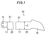
- FIG. 1 is a plan view showing an embodiment of the invention.
- a rotor blade 10 is like a main wing which supports the weight of a helicopter by rotating, and has a root end 9, a central portion 11 and a tip portion 12.
- the root end 9 is a member for attachment to a rotor head which drives the rotor blade 10 to rotate.
- the central portion 11 is formed to extend linearly from the root end, and has a leading edge 21 and a trailing edge 22 which are parallel to each other.
- a chord dimension C of the central portion 11 is defined by the distance between the leading edge 21 and the trailing edge 22.
- the central portion 11 has aerodynamic characteristics which are related to the leading edge 21, the trailing edge 22, chord dimension C.
- Fig.2 is a partially enlarged drawing of the rotor blade 10 of Fig. 1.
- a tip portion 12 is formed on an end of the central portion 11 opposite to the root end 9, with a planform shape being defined by a first leading edge 23, a second leading edge 24, a side edge 25, a first trailing edge 26 and a second trailing edge 27.
- the first leading edge 23 extends forwardly as the distance from an outboard end P1 of the leading edge 21 of the central portion 11 outwardly increases, and extends to an outboard end P of the first leading edge 23.
- Outboard side here refers to the side of blade tip in Y direction (span direction) of the rotor blade 10, and outboard end of the leading edge means the end point on the side of a blade end in the span direction of the rotor blade 10
- the second leading edge 24 is swept rearwardly as the distance from the outboard end P of the first leading edge 23 toward outboard side increases outwardly, and extends to the outboard end point P3 of the second leading edge 24.
- the side edge 25 is swept rearwardly as the distance from the outboard end P3 of the second leading edge 24 toward outboard side increases outwardly, and extends to the trailing end point P4 of the side edge 25.
- the first trailing edge 26 is curved forwardly as the distance from an outboard end P5 of the trailing edge 22 of the central portion 11 increases outwardly, and extends to an outboard end P6 of the first trailing edge 26.
- the second trailing edge 27 is swept rearwardly increasingly toward outboard side to the trailing end point P4 of the side edge 25.
- Fig. 2 are given dimensions of portions of the rotor blade 10, normalized on the basis of the blade length R in Y direction and on the basis of the chord dimension C in X direction to facilitate embodying the invention as various sizes of helicopters.
- a position of the extension on the leading edge or distance R1 in Y direction from the center of rotation to the outboard end P is set to satisfy the following conditional relationship in order to mitigate shock waves: 88%R ⁇ R1 ⁇ 92%R
- An amount of forward extension of the leading edge, namely distance of the outboard end P from the leading edge 21, is set to 25 to 35%C in order to suppress the generation of shock waves and prevent the nose-up pitching moment from increasing.
- the notch in the trailing edge is located at a position corresponding to the forward extension of the leading edge, namely a distance from the outboard end P6 of the first trailing edge 26 is set equal to distance R1, and the outboard end P6 is located at a distance of 10 to 30%C from the trailing edge 22.
- distance R3 from the center of rotation to the outboard end P3 in Y direction is set to 96%R
- a chord dimension passing through the outboard end P3 is set to approximately C
- a rearwardly sweeping angle of the second leading edge 24 is set to 20° to 30° .
- the side edge 25 is swept rearwardly at a steep angle of 60° to 75° from the outboard end P3 thereby tapering down the chord length toward the tip.
- the outline which defines the planform shape described above includes curved sections smoothly joining with each other.
- the planform shape of the rotor blade 10 includes curved sections defined by equations (2) through (11), where an origin of the XY coordinate system being at the center of rotation of the rotor, and a Y axis corresponding to the feathering axis L1.
- An X axis is set such that positive values of X coordinates direct to the rearward side of the blade, and Y axis is set such that Y coordinates positively increase to the blade tip side.
- the feathering axis refers to the axis around which the blade rotates as the angle of attack of the blade is changed.
- the leading edge 21 is defined by a straight line represented by equation (2).
- the first leading edge 23 is defined by equation (3), equation (4) and part of equation (5), which represent a part of circle, a straight line and a part of circle in order from the center of rotation of the rotor, respectively.
- the second leading edge 24 is defined by a part of equation (5) and equation (6), which represent a part of circle and straight line, respectively.
- the side edge 25 is defined by a parabola represented by equation (7).
- the trailing edge 22 is defined by a straight line of equation (8).
- the first trailing edge 26 is defined by a cubical curve represented by equation (9).
- the second trailing edge 27 is defined by a cubical curve represented by equation (10) and a straight line represented by equation (11).
- coordinates Xf, Xr and Y may include errors of about ⁇ 3% introduced during the manufacturing process, and also the coordinates Xf, Xr and Y may be subject to errors of about ⁇ 3% due to thermal deformation and other causes after manufacturing.
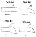
- Figs. 3A through 3D are plan views showing the configurations of the rotor blade 10 and a rotor blade of an comparative example
- Figs. 4A through 4C are equi-Mach number diagrams obtained through CFD analysis.
- the rotor blade 51 shown in Fig. 3A has a rectangular shape.
- the rotor blade 52 shown in Fig. 3B has a leading edge of the tip portion swept rearwardly by a sweptback angle of 30°, while being tapered at a rate of 0.5.
- the rotor blade 53 shown in Fig. 3C is a configuration described in U.S. Patent 4,077,741, with the leading edge of the tip portion extending forwardly and being smoothly swept rearwardly toward the tip end.
- Fig. 3D shows the rotor blade 10, the same as that of Figs.1 and 2. In drawings that follow, the rotor blade 10 will be designated to as AT1.
- a dashed line in Fig.4 indicates the position where Mach number is 1, while the region enclosed by the dashed line is a supersonic region wherein Mach number is not less than 1.
- Figs. 5A through 5D are graphs showing results of analyzing variations of sound pressure in a far field away from each rotor blade (3R from the center of rotation). Times (in seconds) are plotted along the axis of abscissa and sound pressures are plotted along the axis of ordinate.
- the rotor blade 10 causes a less variation of sound pressure in the far field than the rotor blades 51 through 53. This shows that the pressure variation originating from a shock wave generated on the blade is less likely to be transmitted over a distance in the case of the rotor blade 10.
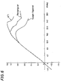
- Fig. 6 is a graph showing angle of attack dependency of lift coefficient.
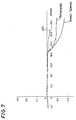
- Fig. 7 is a graph showing angle of attack dependency of pitching moment coefficient. Angle of attack are plotted along the axis of abscissa (in degrees) and the values of the coefficients are plotted along the axis of ordinate. With the rotor blade 10, the stalling angle and maximum lift coefficient Clmax are increased and rapid change in the pitching moment coefficient Cm is suppressed, as compared with the cases of the rotor blades 51, 52.
Landscapes
- Engineering & Computer Science (AREA)
- Mechanical Engineering (AREA)
- Aviation & Aerospace Engineering (AREA)
- Structures Of Non-Positive Displacement Pumps (AREA)
- Turbine Rotor Nozzle Sealing (AREA)
Applications Claiming Priority (2)
| Application Number | Priority Date | Filing Date | Title |
|---|---|---|---|
| JP07021497A JP3170470B2 (ja) | 1997-03-24 | 1997-03-24 | 回転翼機のロータブレード |
| JP70214/97 | 1997-03-24 |
Publications (2)
| Publication Number | Publication Date |
|---|---|
| EP0867363A2 true EP0867363A2 (de) | 1998-09-30 |
| EP0867363A3 EP0867363A3 (de) | 1999-06-02 |
Family
ID=13425067
Family Applications (1)
| Application Number | Title | Priority Date | Filing Date |
|---|---|---|---|
| EP97202756A Withdrawn EP0867363A3 (de) | 1997-03-24 | 1997-09-09 | Rotorblatt eines Drehflügelflugzeuges |
Country Status (3)
| Country | Link |
|---|---|
| US (1) | US6231308B1 (de) |
| EP (1) | EP0867363A3 (de) |
| JP (1) | JP3170470B2 (de) |
Cited By (3)
| Publication number | Priority date | Publication date | Assignee | Title |
|---|---|---|---|---|
| CN102582831A (zh) * | 2010-12-02 | 2012-07-18 | 阿加斯塔西部有限公司 | 机翼 |
| EP2505500A1 (de) * | 2011-03-31 | 2012-10-03 | Eurocopter Deutschland GmbH | Lärm- und leistungsverbessertes Rotorblatt für einen Helikopter |
| WO2013045859A1 (fr) * | 2011-09-29 | 2013-04-04 | Snecma | Pale pour une helice de turbomachine, notamment a soufflante non carenee, helice et turbomachine correspondantes |
Families Citing this family (28)
| Publication number | Priority date | Publication date | Assignee | Title |
|---|---|---|---|---|
| US6497385B1 (en) | 2000-11-08 | 2002-12-24 | Continuum Dynamics, Inc. | Rotor blade with optimized twist distribution |
| US6666648B2 (en) | 2002-05-17 | 2003-12-23 | Sikorsky Aircraft Corporation | Directional elastomeric coupler |
| US6769872B2 (en) | 2002-05-17 | 2004-08-03 | Sikorsky Aircraft Corporation | Active control of multi-element rotor blade airfoils |
| US6932569B2 (en) | 2002-05-17 | 2005-08-23 | Sikorsky Aircraft Corporation | Active control of multi-element rotor blade airfoils |
| US6986642B2 (en) * | 2002-08-30 | 2006-01-17 | Cartercopters, L.L.C. | Extreme mu rotor |
| US6976829B2 (en) * | 2003-07-16 | 2005-12-20 | Sikorsky Aircraft Corporation | Rotor blade tip section |
| US20050281676A1 (en) * | 2004-06-16 | 2005-12-22 | Egolf Thomas A | Multi-hedral rotary wing |
| US20060038058A1 (en) * | 2004-08-23 | 2006-02-23 | Routery Edward E | Active control of airfoils |
| US7246998B2 (en) * | 2004-11-18 | 2007-07-24 | Sikorsky Aircraft Corporation | Mission replaceable rotor blade tip section |
| US8128376B2 (en) * | 2005-08-15 | 2012-03-06 | Abe Karem | High performance outboard section for rotor blades |
| US7762785B2 (en) * | 2007-12-10 | 2010-07-27 | Sikorsky Aircraft Corporation | Main rotor blade with integral tip section |
| US8262344B2 (en) * | 2008-04-02 | 2012-09-11 | Hamilton Sundstrand Corporation | Thermal management system for a gas turbine engine |
| EP2123556B1 (de) * | 2008-05-22 | 2010-12-08 | Agusta S.p.A. | Drehmomentausgleichs-Heckrotorblatt für Hubschrauber |
| US9302766B2 (en) * | 2008-06-20 | 2016-04-05 | Aviation Partners, Inc. | Split blended winglet |
| ES3040742T3 (en) * | 2008-06-20 | 2025-11-04 | Aviation Partners Inc | Curved wing tip |
| DE102009025843B4 (de) | 2009-05-19 | 2022-11-17 | Kronen Gmbh | Vorrichtung und Verfahren zum Trennen von Pflanzenteilen |
| DK3650337T3 (da) | 2011-06-09 | 2021-02-22 | Aviation Partners Inc | Delt "blended" winglet |
| FR3005301B1 (fr) * | 2013-05-03 | 2015-05-29 | Eurocopter France | Rotor carene d'aeronef, et giravion |
| FR3017165B1 (fr) * | 2014-02-05 | 2016-01-22 | Snecma | Pale pour une helice de turbomachine, notamment a soufflante non carenee, helice et turbomachine correspondantes |
| RU2603710C1 (ru) * | 2015-08-24 | 2016-11-27 | Федеральное государственное унитарное предприятие "Центральный аэрогидродинамический институт имени профессора Н.Е. Жуковского" (ФГУП "ЦАГИ") | Лопасть винта винтокрылого летательного аппарата |
| EP3269635A1 (de) * | 2016-07-12 | 2018-01-17 | The Aircraft Performance Company UG | Flugzeugflügel |
| US10899440B2 (en) * | 2017-03-09 | 2021-01-26 | Sikorsky Aircraft Corporation | Rotor blade tip design for improved hover and cruise performance |
| ES2905192T3 (es) * | 2018-01-15 | 2022-04-07 | The Aircraft Performance Company Gmbh | Ala de avión |
| US12269586B2 (en) * | 2018-06-15 | 2025-04-08 | The Texas A&M University System | Hover-capable aircraft |
| GB2616252A (en) * | 2022-01-31 | 2023-09-06 | Airbus Operations Ltd | Aircraft with movable wing tip device |
| GB2615311A (en) * | 2022-01-31 | 2023-08-09 | Airbus Operations Ltd | Aircraft wing with movable wing tip device |
| JP7793500B2 (ja) * | 2022-09-30 | 2026-01-05 | 本田技研工業株式会社 | ブレード及びロータ |
| GB2628523B (en) * | 2022-11-16 | 2025-07-09 | Airbus Operations Ltd | Aircraft wing |
Citations (1)
| Publication number | Priority date | Publication date | Assignee | Title |
|---|---|---|---|---|
| US4077741A (en) | 1975-05-19 | 1978-03-07 | Westland Aircraft Limited | Helicopter rotor blades |
Family Cites Families (9)
| Publication number | Priority date | Publication date | Assignee | Title |
|---|---|---|---|---|
| US3822105A (en) * | 1971-09-22 | 1974-07-02 | United Aircraft Corp | Helicopter blade |
| DE3175016D1 (en) * | 1980-03-28 | 1986-09-04 | Westland Plc | Helicopter rotor blade |
| GB8815955D0 (en) * | 1988-07-05 | 1988-11-16 | Westland Helicopters | Helicopter rotor blades |
| GB9022281D0 (en) * | 1990-10-13 | 1991-02-20 | Westland Helicopters | Helicopter rotor blades |
| GB9022271D0 (en) * | 1990-10-13 | 1991-02-20 | Westland Helicopters | Helicopter rotor blades |
| GB9023141D0 (en) * | 1990-10-24 | 1991-07-10 | Westland Helicopters | Helicopter rotor blades |
| GB9112835D0 (en) * | 1991-06-14 | 1992-05-27 | Westland Helicopters | Helicopter rotor blades |
| US5320494A (en) | 1992-12-22 | 1994-06-14 | United Technologies Corporation | Helicopter rotor blade having a replaceable anhedral tip |
| US5584661A (en) * | 1994-05-02 | 1996-12-17 | The United States Of America As Represented By The Administrator Of The National Aeronautics And Space Administration | Forward sweep, low noise rotor blade |
-
1997
- 1997-03-24 JP JP07021497A patent/JP3170470B2/ja not_active Expired - Fee Related
- 1997-09-08 US US08/925,526 patent/US6231308B1/en not_active Expired - Fee Related
- 1997-09-09 EP EP97202756A patent/EP0867363A3/de not_active Withdrawn
Patent Citations (1)
| Publication number | Priority date | Publication date | Assignee | Title |
|---|---|---|---|---|
| US4077741A (en) | 1975-05-19 | 1978-03-07 | Westland Aircraft Limited | Helicopter rotor blades |
Cited By (11)
| Publication number | Priority date | Publication date | Assignee | Title |
|---|---|---|---|---|
| CN102582831A (zh) * | 2010-12-02 | 2012-07-18 | 阿加斯塔西部有限公司 | 机翼 |
| EP2508423A3 (de) * | 2010-12-02 | 2014-10-08 | AgustaWestland Limited | Tragfläche |
| GB2486021B (en) * | 2010-12-02 | 2017-07-19 | Agustawestland Ltd | Aerofoil |
| EP2505500A1 (de) * | 2011-03-31 | 2012-10-03 | Eurocopter Deutschland GmbH | Lärm- und leistungsverbessertes Rotorblatt für einen Helikopter |
| US9061758B2 (en) | 2011-03-31 | 2015-06-23 | Airbus Helicopters Deutschland GmbH | Noise and performance improved rotor blade for a helicopter |
| WO2013045859A1 (fr) * | 2011-09-29 | 2013-04-04 | Snecma | Pale pour une helice de turbomachine, notamment a soufflante non carenee, helice et turbomachine correspondantes |
| FR2980818A1 (fr) * | 2011-09-29 | 2013-04-05 | Snecma | Pale pour une helice de turbomachine, notamment a soufflante non carenee, helice et turbomachine correspondantes. |
| CN103946110A (zh) * | 2011-09-29 | 2014-07-23 | 斯奈克玛 | 用于涡轮机风机的叶片,尤其用于无导管风机类型的涡轮机风机的叶片、相应的风机和相应的涡轮机 |
| CN103946110B (zh) * | 2011-09-29 | 2016-10-19 | 斯奈克玛 | 用于涡轮机风机的叶片,尤其用于无导管风机类型的涡轮机风机的叶片、相应的风机和相应的涡轮机 |
| RU2606787C2 (ru) * | 2011-09-29 | 2017-01-10 | Снекма | Лопасть для воздушного винта турбомашины, в частности вентилятора без обтекателя, и соответствующие воздушный винт и турбомашина |
| US9630704B2 (en) | 2011-09-29 | 2017-04-25 | Snecma | Blade for a fan of a turbomachine, notably of the unducted fan type, corresponding fan and corresponding turbomachine |
Also Published As
| Publication number | Publication date |
|---|---|
| JPH10264896A (ja) | 1998-10-06 |
| JP3170470B2 (ja) | 2001-05-28 |
| EP0867363A3 (de) | 1999-06-02 |
| US6231308B1 (en) | 2001-05-15 |
Similar Documents
| Publication | Publication Date | Title |
|---|---|---|
| EP0867363A2 (de) | Rotorblatt eines Drehflügelflugzeuges | |
| US6190132B1 (en) | Rotor blade for rotorcraft | |
| US6168383B1 (en) | Rotor blade for rotary-wing aircraft | |
| RU2139811C1 (ru) | Лопасть со стреловидным концом для вращающейся несущей поверхности летательного аппарата | |
| US5884872A (en) | Oscillating flap lift enhancement device | |
| US4880355A (en) | Blade with curved end for a rotary airfoil of an aircraft | |
| US6361279B1 (en) | Blade profile for aircraft rotor and rotor comprising same | |
| CA2759909C (en) | Aerofoil | |
| JPH06305492A (ja) | 回転翼羽根 | |
| JPS6234600B2 (de) | ||
| US20100272576A1 (en) | High performance outboard section for rotor blades | |
| JPS62299466A (ja) | プロペラ | |
| US5961290A (en) | Helicopter blade aerofoil | |
| US5927948A (en) | Propeller | |
| EP0518598B1 (de) | Rotorblätter eines Hubschraubers | |
| US5957662A (en) | helicopter blade aerofoil | |
| US6315522B1 (en) | Helicopter blade aerofoil and helicopter blade | |
| CN104044736A (zh) | 无人直升机旋翼桨尖 | |
| CN106564588B (zh) | 一种无人直升机桨叶及无人直升机 | |
| US6164918A (en) | Helicopter blade aerofoil | |
| CN102428000A (zh) | 提高航空器垂直尾翼的空气动力学效率的方法 | |
| US11192644B2 (en) | Aircraft rotor blade sleeve having a protuberance in its rear zone, and a rotor provided with such a sleeve | |
| CN206456550U (zh) | 一种无人直升机桨叶及无人直升机 | |
| JP2000118499A (ja) | 回転翼機のロータブレード | |
| JP3722961B2 (ja) | 回転翼航空機の回転翼羽根 |
Legal Events
| Date | Code | Title | Description |
|---|---|---|---|
| PUAI | Public reference made under article 153(3) epc to a published international application that has entered the european phase |
Free format text: ORIGINAL CODE: 0009012 |
|
| AK | Designated contracting states |
Kind code of ref document: A2 Designated state(s): DE FR GB IT |
|
| AX | Request for extension of the european patent |
Free format text: AL;LT;LV;RO;SI |
|
| PUAL | Search report despatched |
Free format text: ORIGINAL CODE: 0009013 |
|
| AK | Designated contracting states |
Kind code of ref document: A3 Designated state(s): AT BE CH DE DK ES FI FR GB GR IE IT LI LU MC NL PT SE |
|
| AX | Request for extension of the european patent |
Free format text: AL;LT;LV;RO;SI |
|
| 17P | Request for examination filed |
Effective date: 19991014 |
|
| AKX | Designation fees paid |
Free format text: DE FR GB IT |
|
| STAA | Information on the status of an ep patent application or granted ep patent |
Free format text: STATUS: THE APPLICATION HAS BEEN WITHDRAWN |
|
| 18W | Application withdrawn |
Withdrawal date: 20020717 |