EP0867582A2 - Möbelschloss - Google Patents
Möbelschloss Download PDFInfo
- Publication number
- EP0867582A2 EP0867582A2 EP98101584A EP98101584A EP0867582A2 EP 0867582 A2 EP0867582 A2 EP 0867582A2 EP 98101584 A EP98101584 A EP 98101584A EP 98101584 A EP98101584 A EP 98101584A EP 0867582 A2 EP0867582 A2 EP 0867582A2
- Authority
- EP
- European Patent Office
- Prior art keywords
- bolt
- opening
- cylinder core
- cylinder
- lock
- Prior art date
- Legal status (The legal status is an assumption and is not a legal conclusion. Google has not performed a legal analysis and makes no representation as to the accuracy of the status listed.)
- Ceased
Links
- 230000037431 insertion Effects 0.000 claims description 4
- 238000003780 insertion Methods 0.000 claims description 4
- 230000015572 biosynthetic process Effects 0.000 description 1
- 230000003993 interaction Effects 0.000 description 1
Images


Classifications
-
- E—FIXED CONSTRUCTIONS
- E05—LOCKS; KEYS; WINDOW OR DOOR FITTINGS; SAFES
- E05B—LOCKS; ACCESSORIES THEREFOR; HANDCUFFS
- E05B9/00—Lock casings or latch-mechanism casings ; Fastening locks or fasteners or parts thereof to the wing
- E05B9/08—Fastening locks or fasteners or parts thereof, e.g. the casings of latch-bolt locks or cylinder locks to the wing
- E05B9/084—Fastening of lock cylinders, plugs or cores
- E05B9/086—Fastening of rotors, plugs or cores to an outer stator
-
- E—FIXED CONSTRUCTIONS
- E05—LOCKS; KEYS; WINDOW OR DOOR FITTINGS; SAFES
- E05B—LOCKS; ACCESSORIES THEREFOR; HANDCUFFS
- E05B65/00—Locks or fastenings for special use
- E05B65/44—Locks or fastenings for special use for furniture
-
- E—FIXED CONSTRUCTIONS
- E05—LOCKS; KEYS; WINDOW OR DOOR FITTINGS; SAFES
- E05C—BOLTS OR FASTENING DEVICES FOR WINGS, SPECIALLY FOR DOORS OR WINDOWS
- E05C3/00—Fastening devices with bolts moving pivotally or rotatively
- E05C3/02—Fastening devices with bolts moving pivotally or rotatively without latching action
- E05C3/04—Fastening devices with bolts moving pivotally or rotatively without latching action with operating handle or equivalent member rigid with the bolt
- E05C3/041—Fastening devices with bolts moving pivotally or rotatively without latching action with operating handle or equivalent member rigid with the bolt rotating about an axis perpendicular to the surface on which the fastener is mounted
- E05C3/042—Fastening devices with bolts moving pivotally or rotatively without latching action with operating handle or equivalent member rigid with the bolt rotating about an axis perpendicular to the surface on which the fastener is mounted the handle being at one side, the bolt at the other side or inside the wing
Definitions
- the invention relates to a furniture lock with a cylinder housing and a Interchangeable core formed cylinder core with a locking cylinder bolt and a movable bolt between a closed position and an open position with a bolt drive eccentric coupled to the bolt, the cylinder core at the end a drive element, in particular a square, for engaging in a corresponding drive opening, in particular a square opening, of the bolt drive eccentric having.
- a furniture lock of the type mentioned is known from practice.
- Furniture lock can be the cylinder core usually referred to as an interchangeable core pull out of the cylinder housing using a so-called interchangeable key.
- An interchangeable core is always used in a furniture lock in particular if the furniture lock as both left and right lock, d. H. For a right lock that can be used for a left door.
- the object of the present invention is to provide a furniture lock of the type mentioned To make available in which a pulling out of the removable core in particular to move the furniture lock from right to left or from left to right only in an unlocked state, d. H. is possible in the open position of the bolt.
- the drive opening in the bolt drive eccentric is designed as a through opening that an opening is provided in the bolt through which the drive element or one connected to the drive element Component is passed and that the drive element / the component and / or the Opening are designed such that pulling out the cylinder core is not possible is when the bolt is in the closed position.
- the opening in the bolt has such a shape that the drive element or the component engages behind the bolt at least in the closed position. This results in a form fit. As long as the bolt is engaged by the drive element or the component, the removable core cannot be removed.
- the opening in the bolt expediently has one in the direction of movement of the Tie's elongated shape.
- the opening is at one end in the Width reduced, so that the area engaging behind the bolt is made relatively small can be. At least at the other end of the opening, the width is such that the cylinder core can be pulled out of the cylinder housing.
- the drive element passed through the opening. So it is not a special component that with the It is necessary to connect the drive element.
- the drive element then has one preferably circumferential groove with a portion projecting at the end, wherein the groove is intended to cooperate with the narrower end of the opening is.
- the aforementioned embodiment means that it is only constructive the drive element, d. H. the square, slightly elongated and in its End area must be provided with a cut groove into which the latch engages through its opening in the closed position.
- the effective one Length of the opening in the direction of movement of the bolt such that an angle of rotation of the cylinder core of about 180 ° is possible.
- the bolt is usually provided in a lock case. Because that through the Opening in the bolt drive element required space is located in the Lock case another opening for the drive element. So that the drive element does not survive, it is expediently provided that the drive element at least substantially aligned at the end with the lock case is.
- exchangeable cores are used in particular Furniture locks used that are used as both left and right locks can be.
- To lock the cylinder core in the cylinder housing is in this a stop to interact with a locking tumbler of the cylinder core intended.
- It is now essential for such a left and right lock trained furniture lock that behind in the insertion direction of the cylinder core the side flank to determine the angle of rotation of the cylinder core are provided that interact with the corresponding side surfaces serve as a locking device.
- the side flanks are arranged in this way and designed so that the angle of rotation of the cylinder core is approximately 180 °.
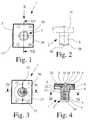
- a furniture lock 1 is shown, both as a so-called legal can also be used as a so-called left lock.
- the furniture lock 1 has in the present case a lock cylinder 2, which in turn consists of a cylinder housing 3 and a cylinder core 4 designed as an exchangeable core.
- the furniture lock 1 has a bolt 5 which is between a closed position, as shown for example in FIGS. 5, 6 and 9, and an open position, as shown for example in FIGS. 3, 4 and 8, is movable.
- the furniture lock 1 has a bolt drive eccentric 6, which with the Latch 5 is coupled in a manner known per se. The bolt drive eccentric is used for this 6 with its eccentric section 7 into a corresponding bolt opening 8.
- the bolt 5 is arranged in a lock case 11, which receives the bolt 5 and the bolt drive eccentric 6.
- the lock case 11 serves a lock cover 12, which in the present case is in one piece with the cylinder housing 3 is formed.
- the square opening 10 in the bolt drive eccentric 6 as Through opening, namely without gradation or the like. Is formed, and that in Bolt 5 an opening 13, which is also a through opening, is provided.
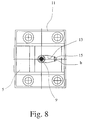
- the opening 13 can be seen particularly well in FIGS. 8 and 9.
- the square 9 is passed through the opening 13, as is the case in particular 4, 6 and 7.
- the formation of the square 9 and the opening 13 is such that pulling out the cylinder core 4 in the closed position of the bolt 5, as shown for example in FIGS. 5 and 6, not possible. Only in the open position, as shown in FIGS. 3 and 4, can the cylinder core 4 with an interchangeable key 14, as shown in FIG. 10, pull out.
- the opening 13 in the bolt 5 has an elongated one in the direction of movement of the bolt 5 Shape that emerges in particular from FIGS. 8 and 9.
- the opening 13 has at one end 15 a smaller width b, while at its other end 16 has a width B such that the cylinder core 4 out of the cylinder housing 3 can be pulled. This is solved constructively in such a way that the width B is approximately gradually reduced to the width b from the center of the opening 13, namely from both sides out evenly.
- the width B is chosen such that the square 9 can be easily rotated in the opening 13 without the edge of the opening 13 to post. This state is shown in Fig. 8.
- section 18 is represented by a further opening 19 is passed in the lock case 11 and over the outer wall 20 of the lock case 11 is in an embodiment, not shown provided that the section 18 is approximately aligned with the outer wall 20 is not survived.
- the furniture lock 1 is designed as a right-hand lock, that is to say Intended for a right-hand furniture door.
- the furniture lock is the opposite 1 in the embodiments according to FIGS. 5, 6 and 9 designed as a left lock. Ultimately, however, it is the same furniture lock in both cases 1, wherein only the cylinder core 4 has been rotated.
- circumferential stop 21 is provided in the cylinder housing 3.
- the attack 21 is used to interact with a locking tumbler 22, in particular 3 and 5 is shown.
- the locking tumbler 22 is known per se Way spring-loaded via a spring 23.
- the illustrated Cylinder core 4 still a number of plate tumblers 24, wherein the locking tumbler 22 represents the last or rearmost tumbler.
- lateral flanks 25, 26, which serve to determine the angle of rotation of the cylinder core 4.
- the two side flanks 25, 26 are aligned and arranged and designed so that the angle of rotation of the cylinder core 4 is approximately 180 °. This is shown in FIGS. 3 and 5 by the movement arrows shown there shown. It is not shown in detail that the stop 21 and the Flanks 25, 26 are formed in one piece.
- the marking 30 has the shape of an upward directional arrowhead. This indicates to the user that the cylinder core 4 must always be used with the mark 30 pointing upwards.
Landscapes
- Engineering & Computer Science (AREA)
- Mechanical Engineering (AREA)
- Lock And Its Accessories (AREA)
- Closing And Opening Devices For Wings, And Checks For Wings (AREA)
Abstract
Description
- Fig. 1
- eine Vorderansicht eines erfindungsgemäßen Möbelschlosses,
- Fig. 2
- eine Ansicht des Möbelschlosses aus Fig. 1 in Pfeilrichtung II aus Fig. 1,
- Fig. 3
- eine Querschnittsansicht des in Fig. 4 dargestellten Möbelschlosses entlang der Schnittlinie III - III aus Fig. 4,
- Fig. 4
- eine Querschnittsansicht des Möbelschlosses aus Fig. 3 entlang der Schnittlinie IV - IV aus Fig. 3,
- Fig. 5
- eine Querschnittsansicht des in Fig. 6 dargestellten Möbelschlosses entlang der Schnittlinie V - V aus Fig. 6,
- Fig. 6
- eine Querschnittsansicht des Möbelschlosses aus Fig. 5 entlang der Schnittlinie V - V aus Fig. 6,
- Fig. 7
- eine Querschnittsseitenansicht des erfindungsgemäßen Möbelschlosses aus Fig. 1 entlang der Schnittlinie VII - VII aus Fig. 1,
- Fig. 8
- eine Querschnittsansicht des Möbelschlosses aus Fig. 7 entlang der Schnittlinie VIII - VIII aus Fig. 7,
- Fig. 9
- eine der Fig. 8 entsprechende Ansicht des Möbelschlosses mit sich in Schließstellung befindendem Riegel,
- Fig. 10
- eine Draufsicht auf einen Wechselschlüssel und
- Fig. 11
- eine Draufsicht auf einen Zylinderschlüssel.
Claims (9)
- Möbelschloß (1) mit einem ein Zylindergehäuse (3) und einen als Wechselkern ausgebildeten Zylinderkern (4) aufweisenden Schließzylinder (2), mit einem zwischen einer Schließstellung und einer Öffnungsstellung bewegbaren Riegel (5) und mit einem mit dem Riegel (5) gekoppelten Riegelantriebsexzenter (6), wobei der Zylinderkern (4) endseitig ein Antriebselement, insbesondere einen Vierkant (9), zum Eingriff in eine korrespondierende Antriebsöffnung, insbesondere eine Vierkantöffnung (10), des Riegelantriebsexzenters (6) aufweist, dadurch gekennzeichnet, daß die Antriebsöffnung im Riegelantriebsexzenter (6) als Durchgangsöffnung ausgebildet ist, daß im Riegel (5) eine Öffnung (13) vorgesehen ist, durch die das Antriebselement oder ein mit dem Antriebselement verbundenes Bauteil hindurchgeführt ist und daß das Antriebselement/das Bauteil und/oder die Öffnung (13) derart ausgebildet sind, daß ein Herausziehen des Zylinderkerns (4) nicht möglich ist, wenn sich der Riegel (5) in der Schließstellung befindet.
- Möbelschloß nach Anspruch 1, dadurch gekennzeichnet, daß die Öffnung (13) im Riegel (5) eine solche Form aufweist, daß das Antriebselement oder das Bauteil zumindest in der Schließstellung den Riegel (5) hintergreift.
- Möbelschloß nach Anspruch 1 oder 2, dadurch gekennzeichnet, daß die Öffnung (13) im Riegel (5) eine in Bewegungsrichtung des Riegels (5) langgestreckte Form aufweist, daß die Breite (b) der Öffnung (13) an ihrem einen Ende (15) verringert ist, während die Breite (B) der Öffnung (13) zumindest am anderen Ende (16) derart ist, daß der Zylinderkern (4) aus dem Zylindergehäuse (3) herausgezogen werden kann.
- Möbelschloß nach einem der Ansprüche 1 bis 3, dadurch gekennzeichnet, daß das Antriebselement durch die Öffnung (13) hindurchgeführt ist und eine vorzugsweise umlaufende Nut (17) mit einem endseitig überstehenden Abschnitt (18) aufweist, wobei der sich in der Schließstellung befindende Riegel (5) am schmaleren Ende (15) der Öffnung (13) in die Nut (17) eingreift.
- Möbelschloß nach einem der Ansprüche 1 bis 4, dadurch gekennzeichnet, daß die wirksame Länge der Öffnung (13) in Bewegungsrichtung des Riegels (5) derart ist, daß sich ein Drehwinkel des Zylinderkerns (4) von etwa 180° ergibt.
- Möbelschloß nach einem der Ansprüche 1 bis 5, dadurch gekennzeichnet, daß ein den Riegel (5) aufnehmender Schloßkasten (11) vorgesehen ist, daß im Schloßkasten (11) eine weitere Öffnung (19) für das Antriebselement vorgesehen ist und daß, vorzugsweise, das Antriebselement endseitig mit der Außenwandung (20) des Schloßkastens (11) zumindest im wesentlichen ausgefluchtet ist.
- Möbelschloß nach einem der Ansprüche 1 bis 6, dadurch gekennzeichnet, daß das Möbelschloß (1) als Links- und als Rechtsschloß ausgebildet ist, daß im Zylindergehäuse (3) ein Anschlag (21) zum Zusammenwirken mit einer Sperrzuhaltung (22) des Zylinderkerns (4) vorgesehen ist, daß in Einschiebrichtung des Zylinderkerns (4) hinter dem Anschlag (21) seitliche Flanken (25, 26) zur Drehwinkelfestlegung des Zylinderkerns (4) ausgebildet sind, die zum Zusammenwirken mit korrespondierenden Seitenflächen (27, 28) der Sperrzuhaltung (22) dienen, und daß die seitlichen Flanken (25, 26) derart angeordnet und ausgebildet sind, daß der Drehwinkel des Zylinderkerns (4) etwa 180° beträgt.
- Möbelschloß nach Anspruch 7, dadurch gekennzeichnet, daß der Anschlag (21) und die Flanken (25, 26) einteilig ausgebildet sind.
- Möbelschloß nach einem der Ansprüche 1 bis 8, dadurch gekennzeichnet, daß am Kopf (29) des Zylinderkerns (4) eine insbesondere nach oben weisende Markierung (30) vorgesehen ist.
Applications Claiming Priority (2)
| Application Number | Priority Date | Filing Date | Title |
|---|---|---|---|
| DE19712995 | 1997-03-27 | ||
| DE19712995A DE19712995C2 (de) | 1997-03-27 | 1997-03-27 | Möbelschloß |
Publications (2)
| Publication Number | Publication Date |
|---|---|
| EP0867582A2 true EP0867582A2 (de) | 1998-09-30 |
| EP0867582A3 EP0867582A3 (de) | 1999-06-09 |
Family
ID=7824859
Family Applications (1)
| Application Number | Title | Priority Date | Filing Date |
|---|---|---|---|
| EP98101584A Ceased EP0867582A3 (de) | 1997-03-27 | 1998-01-30 | Möbelschloss |
Country Status (2)
| Country | Link |
|---|---|
| EP (1) | EP0867582A3 (de) |
| DE (1) | DE19712995C2 (de) |
Families Citing this family (2)
| Publication number | Priority date | Publication date | Assignee | Title |
|---|---|---|---|---|
| DE10334592A1 (de) * | 2003-07-28 | 2005-02-24 | Beloxx Gmbh & Co. Kg | Anordnung als Teil eines Schließmechanismus |
| DE202012100371U1 (de) * | 2012-02-03 | 2013-05-06 | Martin Lehmann Gmbh & Co. Kg | Wechselzylindersystem und Möbelschloss |
Family Cites Families (6)
| Publication number | Priority date | Publication date | Assignee | Title |
|---|---|---|---|---|
| DE2325627C2 (de) * | 1973-05-21 | 1983-10-06 | Huwil-Werke Gmbh Moebelschloss- Und Beschlagfabriken, 5207 Ruppichteroth | Fallenschloß |
| US3971239A (en) * | 1975-02-07 | 1976-07-27 | Phelps Time Recording Lock Corporation | Lock |
| DE4008649A1 (de) * | 1990-03-17 | 1991-09-19 | Huwil Werke Gmbh | Schloss mit einem schliesszylinder mit auswechselbarem zylinderkern |
| DE19504718C2 (de) * | 1995-02-14 | 1996-12-12 | Niederdrenk Julius Kg | Schließeinrichtung für ein öffenbares Möbelteil |
| DE19509114C2 (de) * | 1995-03-16 | 1997-02-27 | Niederdrenk Julius Kg | Schließeinrichtung |
| DE19511445C2 (de) * | 1995-03-30 | 1998-03-19 | Niederdrenk Julius Kg | Einsatzgehäuse und Schließeinrichtung mit einem Einsatzgehäuse |
-
1997
- 1997-03-27 DE DE19712995A patent/DE19712995C2/de not_active Expired - Fee Related
-
1998
- 1998-01-30 EP EP98101584A patent/EP0867582A3/de not_active Ceased
Also Published As
| Publication number | Publication date |
|---|---|
| EP0867582A3 (de) | 1999-06-09 |
| DE19712995C2 (de) | 1999-03-25 |
| DE19712995A1 (de) | 1998-10-01 |
Similar Documents
| Publication | Publication Date | Title |
|---|---|---|
| DE2840285C2 (de) | ||
| DE3838481A1 (de) | Zylinderschloss | |
| DE3225952A1 (de) | Schliesszylinder-flachschluessel | |
| DE2831896A1 (de) | Tuerschloss mit schluesselbetaetigbarem schliesszylinder | |
| EP1049846B1 (de) | Türschloss für eine ganzglastür mit feststehendem glasseitenteil | |
| EP0792981A1 (de) | Einbau-Doppelschliesszylinder für ein Sicherheitsschloss | |
| DE102012101117A1 (de) | Stangenschloss mit zusätzlicher Stangenstabilisierung | |
| DE29509503U1 (de) | Mehrfachverriegelungsanlage | |
| DE19712995C2 (de) | Möbelschloß | |
| DE202019102154U1 (de) | Modulartig aufgebauter Schließzylinder | |
| DE9403985U1 (de) | Türriegel | |
| DE8534096U1 (de) | Zylinderschloß mit einer Nachschließsicherung | |
| DE102006021172B4 (de) | Elektronischer Schlüssel mit mechanischem Notschlüssel für Verschlüsse in Fahrzeugen | |
| EP0756052B1 (de) | Schliesszylinder mit Stiftzuhaltungen sowie Schlüssel für einen Schliesszylinder mit Stiftzuhaltungen | |
| EP0605820A1 (de) | Sicherheitsschalter | |
| DE3226607A1 (de) | Einbau-doppel-profil-zylinderschloss mit zylinderkern und mit diesem fest verbundenem mitnehmer | |
| CH635647A5 (en) | Double-cylinder lock | |
| DE806211C (de) | Drueckerschloss | |
| EP1347129B1 (de) | Schloss für Sicherheitstüren | |
| DE3042611A1 (de) | Schloss | |
| CH668285A5 (de) | Schloss fuer justizvollzugsanstalten. | |
| AT328908B (de) | Fallenriegelschloss | |
| DE3321323C2 (de) | Abtastsicherungseinrichtung für einen Schließzylinder | |
| DE7800327U1 (de) | Zuhaltungsschloss | |
| DE3305209A1 (de) | Tuerschloss |
Legal Events
| Date | Code | Title | Description |
|---|---|---|---|
| PUAI | Public reference made under article 153(3) epc to a published international application that has entered the european phase |
Free format text: ORIGINAL CODE: 0009012 |
|
| AK | Designated contracting states |
Kind code of ref document: A2 Designated state(s): DE ES FR GB IT |
|
| AX | Request for extension of the european patent |
Free format text: AL;LT;LV;MK;RO;SI |
|
| PUAL | Search report despatched |
Free format text: ORIGINAL CODE: 0009013 |
|
| AK | Designated contracting states |
Kind code of ref document: A3 Designated state(s): AT BE CH DE DK ES FI FR GB GR IE IT LI LU MC NL PT SE |
|
| AX | Request for extension of the european patent |
Free format text: AL;LT;LV;MK;RO;SI |
|
| 17P | Request for examination filed |
Effective date: 19990622 |
|
| AKX | Designation fees paid |
Free format text: DE ES FR GB IT |
|
| GRAG | Despatch of communication of intention to grant |
Free format text: ORIGINAL CODE: EPIDOS AGRA |
|
| 17Q | First examination report despatched |
Effective date: 20010615 |
|
| STAA | Information on the status of an ep patent application or granted ep patent |
Free format text: STATUS: THE APPLICATION HAS BEEN REFUSED |
|
| 18R | Application refused |
Effective date: 20011220 |