EP0867688A2 - Wegmessvorrichtung - Google Patents
Wegmessvorrichtung Download PDFInfo
- Publication number
- EP0867688A2 EP0867688A2 EP98104971A EP98104971A EP0867688A2 EP 0867688 A2 EP0867688 A2 EP 0867688A2 EP 98104971 A EP98104971 A EP 98104971A EP 98104971 A EP98104971 A EP 98104971A EP 0867688 A2 EP0867688 A2 EP 0867688A2
- Authority
- EP
- European Patent Office
- Prior art keywords
- measuring device
- light guide
- optical fiber
- position measuring
- housing
- Prior art date
- Legal status (The legal status is an assumption and is not a legal conclusion. Google has not performed a legal analysis and makes no representation as to the accuracy of the status listed.)
- Granted
Links
Images
Classifications
-
- G—PHYSICS
- G01—MEASURING; TESTING
- G01B—MEASURING LENGTH, THICKNESS OR SIMILAR LINEAR DIMENSIONS; MEASURING ANGLES; MEASURING AREAS; MEASURING IRREGULARITIES OF SURFACES OR CONTOURS
- G01B11/00—Measuring arrangements characterised by the use of optical techniques
- G01B11/16—Measuring arrangements characterised by the use of optical techniques for measuring the deformation in a solid, e.g. optical strain gauge
- G01B11/18—Measuring arrangements characterised by the use of optical techniques for measuring the deformation in a solid, e.g. optical strain gauge using photoelastic elements
-
- G—PHYSICS
- G01—MEASURING; TESTING
- G01B—MEASURING LENGTH, THICKNESS OR SIMILAR LINEAR DIMENSIONS; MEASURING ANGLES; MEASURING AREAS; MEASURING IRREGULARITIES OF SURFACES OR CONTOURS
- G01B11/00—Measuring arrangements characterised by the use of optical techniques
- G01B11/02—Measuring arrangements characterised by the use of optical techniques for measuring length, width or thickness
Definitions
- the invention relates in particular to a displacement measuring device for use in an extensometer for measurement and Monitoring of movements in rock and soil mechanics.
- the one or more optical strain gauges have at least one optical fiber, in particular a glass fiber exist in the Light initiated and at the exit end regarding its spectrum is examined. If with that the test specimen or section provided with the strain gauge If a stretch occurs, the fiber will also stretched so that there is a change in density in the glass fiber that adjusts the reflection and diffraction properties the fiber optic changed. This is known as the "Bragg Grid" Phenomenon occurs at the exit end of the Glass fiber by changing the measurable light spectrum noticeable. By evaluating the spectrum of the end of the Glass fiber emerging light can be a change in Determine the state of elongation of the glass fiber so that the Movements and strains of the with the strain gauge provided test specimen can be determined.
- the invention has for its object a displacement measuring device of the type mentioned, with which too larger strains or paths can be reliably detected can.
- a displacement measuring device solved, the one taking the path to be measured, movable anchor part, at least one light guide, depending on the displacement of the anchor part is stretchable and has an evaluation device, by means of which change depending on the elongation Reflection or transmission properties of the Light guide can be detected, between the anchor part and the light guide the displacement of the anchor part converting into a smaller expansion path of the light guide Reduction device is arranged.
- the anchor part which is preferably an in a measuring pin slidably mounted, with the path to be measured or the path to be measured Elongation applied either directly or indirectly.
- the displacement of the anchor part is not direct on the optical fiber, which has at least one optical fiber, in particular comprises a glass fiber, as an expansion path applied, but via the intermediate reduction device reduced in a preselected ratio. This way, even relatively large ones of which Anchor part detected movements by means of the light guide in initially recorded and evaluated.
- the invention provides that the reduction device is a feather.
- the movement of the Anchor part over the spring in one of the spring constant dependent force applied to the light guide and there depending on its geometric and material parameters for an elongation leads.
- the use of the spring has the advantage that when using a very soft spring too large movements of the anchor part in a simple manner only a small force and therefore a correspondingly small one Elongation of the light guide can be implemented.
- the spring can also serve at the same time to keep the anchor part under a certain pre-tension, in order to achieve its play-free shift.
- the optical fiber inside a housing runs or is tensioned and with one in the housing slidably guided slide is connected, on which the spring engages.
- the slider it has proven to be beneficial proven to design the slider as a pulley, so that the optical fiber is loop-shaped in the housing can be arranged.
- the two can be free Optical fiber ends on one side of the housing be fixed while the optical fiber on the other End of the housing is guided around the pulley, so that one of the anchor part or the spring on the pulley applied force to two parallel ones Optical fiber sections is divided.
- the optical fiber it is also possible for the optical fiber to be single lane tighten. To protect the optical fiber, this should be in a protective cover made of plastic or steel and move along it.
- the slider can be surface polished and / or made of a material with a low coefficient of friction exist to the friction losses when the force is applied in the optical fiber sections to keep it low.
- the slider should be made as light as possible or consist of a light material.
- the optical fiber is built in so that it can be used in every Operating condition is under axial tension.
- the Optical fiber is fixed in a clamping piece that by means of an adjusting device relative to the housing is adjustable, reducing the tension of the optical fiber can be changed.
- an adjustment device For example, an adjusting screw can be used.
- the optical fiber For attaching the optical fiber to the clamping piece it has proven itself, at least on the optical fiber fix one end in a capillary tube, which in turn is held on the clamping piece.
- an adhesive can be used, so that the adhesive yields in the event of excessive tensile forces, without the optical fiber tearing.
- the glue designed so that the adhesive peels off before the Optical fiber undergoes plastic stretching.
- the anchor part is out of position during a measurement, in which the optical fiber has a relatively large tensile elongation has a position that one corresponds to lower tensile elongation of the optical fiber possibly the elastic restoring or retracting force the optical fiber is not sufficient to the on the slider to overcome occurring frictional forces.
- the elastic restoring or retracting force the optical fiber is not sufficient to the on the slider to overcome occurring frictional forces.
- the return spring preferably extends between the slider and the housing.
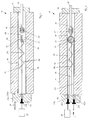
- a displacement measuring device 10 a substantially tubular housing 11 on the one, according to the Fig. Right side with a cover 14 is closed by a measuring pin 15th is penetrated, the axially displaceable in the cover 14 is held.
- the measuring pin 15 is on its inner, in the housing 11 arranged end over a not shown Connecting element 19 with one end of a spring 17th connected at its other end via a connecting element 18 on a movable along the housing 11 Sliders in the form of a guide roller 20 attacks. This ensures that none of the measuring pin 15 Rotational movements are transmitted to the spring 17 because this would lead to torsional forces in the spring 17.
- the deflection roller 20 is seated guide pins 21 projecting on both sides, each in one formed on the inner wall of the housing 11 Engage longitudinal groove 16 slidably. That way the deflection roller 20 is axially displaceable in the housing 11, however held in a rotationally fixed manner.
- a clamping plate 13 is provided, the distance from which Front side of the housing 11 by means of an adjusting screw 24 is changeable.
- the clamping plate 13 are two parallel bores 13a, 13b formed.
- One under Tensioned glass fiber 22 runs from the outside the clamping plate 13 through the bore 13a into the interior 12 of the housing 11 around the deflection roller 20 around and back from there through hole 13b on the outside of the clamping plate 13.
- two Capillary tubes 23 are the glass fibers 22 on the clamping plate 13 held. As shown in Fig. 2, light L on one End of the fiber 22 are introduced into this, wherein the light emerging at the other end of the glass fiber 22 by means of a spectrometer indicated only schematically 25 is recorded and evaluated.
- One end of the slider 20 also engages very soft return spring 26 on her other End stored in a manner not shown on the housing 11 is.
- the measuring pin 15 When the measuring pin 15 receives a tensile force, i. H. around a small amount is pulled out of the housing 11 leads this leads to an expansion of the spring 17, which results in the deflection roller 20 one of the spring constant of the spring 17th dependent tractive force occurs as a reaction force, which in the two sections of the optical fiber 22 shown is initiated and leads to its expansion. At the same time the return spring 26 is stretched. Because of the stretch the glass fiber 22 changes the spectrum on the output side End of the glass fiber emerging light, what is determined and detected by means of the spectrometer 25 becomes.
- the measuring pin 15 is then a small amount in the housing 11 is pushed in, the Expansion of the spring 17 and thus that of the spring 17 the guide roller 20 exerted force so that the guide roller 20 due to the elastic restoring force of the glass fiber 22 undergoes a displacement in the housing 11, what by the force of the return spring 26 is supported.
Landscapes
- Physics & Mathematics (AREA)
- General Physics & Mathematics (AREA)
- Length Measuring Devices By Optical Means (AREA)
- Investigating Or Analysing Materials By Optical Means (AREA)
Abstract
Description
- Fig. 1
- einen Vertikalschnitt durch eine erfindungsgemäße Wegmeßvorrichtung in schematischer Darstellung und
- Fig. 2
- einen Horizontalschnitt durch die Wegmeßvorrichtung gemäß Fig. 1.
Claims (16)
- Wegmeßvorrichtung mit einem den zu messenden Weg aufnehmenden, verschieblichen Ankerteil (15), zumindest einem Lichtleiter (22), der in Abhängigkeit von der Verschiebung des Ankerteils (15) dehnbar ist, und einer Auswerteeinrichtung (25), mittels der die sich in Abhängigkeit von der Dehnung ändernden Reflexions- bzw. Transmissionseigenschaften des Lichtleiters (22) erfaßbar sind, wobei zwischen dem Ankerteil (15) und dem Lichtleiter (22) eine den Verschiebeweg des Ankerteils (15) in einen kleineren Dehnungsweg des Lichtleiters (22) umsetzende Reduktionsvorrichtung (17) angeordnet ist.
- Wegmeßvorrichtung nach Anspruch 1, dadurch gekennzeichnet, daß die Reduktionsvorrichtung eine Feder (17) ist.
- Wegmeßvorrichtung nach Anspruch 1 oder 2, dadurch gekennzeichnet, daß der Lichtleiter zumindest eine Lichtleitfaser (22) umfaßt.
- Wegmeßvorrichtung nach Anspruch 3, dadurch gekennzeichnet, daß die Lichtleitfaser (22) in einem Gehäuse (11) gespannt ist und mit einem im Gehäuse (11) verschieblich geführten Gleitstück (20) in Verbindung steht, an dem die Feder (17) angreift.
- Wegmeßvorrichtung nach Anspruch 4, dadurch gekennzeichnet, daß das Gleitstück eine Umlenkrolle (20) aufweist und daß die Lichtleitfaser (22) in dem Gehäuse (11) schlaufenförmig verläuft.
- Wegmeßvorrichtung nach Anspruch 4 oder 5, dadurch gekennzeichnet, daß das Gleitstück (20) Führungsstifte (21) aufweist, die in auf der Innenwandung des Gehäuses (11) ausgebildete Längsnuten (16) eingreifen.
- Wegmeßvorrichtung nach einem der Ansprüche 3 bis 6, dadurch gekennzeichnet, daß die Lichtleitfaser eine Glasfaser ist.
- Wegmeßvorrichtung nach einem der Ansprüche 3 bis 7, dadurch gekennzeichnet, daß die Lichtleitfaser (22) in einem Spannstück (13) fixiert ist.
- Wegmeßvorrichtung nach Anspruch 8, dadurch gekennzeichnet, daß die Lichtleitfaser (22) in einem am Spannstück (13) gehaltenen Kapillarrohr (23) verklebt ist.
- Wegmeßvorrichtung nach Anspruch 8 oder 9, dadurch gekennzeichnet, daß das Spannstück (13) mittels einer Einstellvorrichtung (24) relativ zum Gehäuse (11) verstellbar ist.
- Wegmeßvorrichtung nach einem der Ansprüche 3 bis 10, dadurch gekennzeichnet, daß in der Lichtleitfaser (22) ein Bragg-Gitter angeordnet ist.
- Wegmeßvorrichtung nach einem der Ansprüche 1 bis 11, dadurch gekennzeichnet, daß das Ankerteil ein Meßstift (15) ist.
- Wegmeßvorrichtung nach einem der Ansprüche 1 bis 12, dadurch gekennzeichnet, daß der Lichtleiter (22) unter einer Zugspannung gehalten ist und daß eine in parallel zur Rückstellkraft des Lichtleiters (22) wirksame Rückstellfeder (26) angeordnet ist.
- Wegmeßvorrichtung nach Anspruch 13, dadurch gekennzeichnet, daß die Federkonstante der Rückstellfeder (26) wesentlich geringer als die Federkonstante der Feder (17) ist.
- Wegmeßvorrichtung nach Anspruch 13 oder 14, dadurch gekennzeichnet, daß die Rückstellfeder (26) zwischen dem Gleitstück (20) und dem Gehäuse (11) wirksam ist.
- Wegmeßvorrichtung nach einem der Ansprüche 1 bis 15 zur Verwendung in einem Extensometer zur Messung und Überwachung von Bewegungen in der Fels- und Bodenmechanik.
Applications Claiming Priority (2)
| Application Number | Priority Date | Filing Date | Title |
|---|---|---|---|
| DE19712407 | 1997-03-25 | ||
| DE19712407A DE19712407A1 (de) | 1997-03-25 | 1997-03-25 | Wegmeßvorrichtung |
Publications (3)
| Publication Number | Publication Date |
|---|---|
| EP0867688A2 true EP0867688A2 (de) | 1998-09-30 |
| EP0867688A3 EP0867688A3 (de) | 1999-07-07 |
| EP0867688B1 EP0867688B1 (de) | 2004-09-08 |
Family
ID=7824504
Family Applications (1)
| Application Number | Title | Priority Date | Filing Date |
|---|---|---|---|
| EP98104971A Expired - Lifetime EP0867688B1 (de) | 1997-03-25 | 1998-03-19 | Wegmessvorrichtung |
Country Status (3)
| Country | Link |
|---|---|
| EP (1) | EP0867688B1 (de) |
| DE (2) | DE19712407A1 (de) |
| ES (1) | ES2229406T3 (de) |
Cited By (7)
| Publication number | Priority date | Publication date | Assignee | Title |
|---|---|---|---|---|
| EP1124112A3 (de) * | 2000-02-10 | 2002-01-02 | NTT Advanced Technology Corporation | Fiberoptischer Sensor |
| EP1992906A1 (de) | 2007-05-16 | 2008-11-19 | Commissariat A L'Energie Atomique - CEA | Bragg-Gitter-Extensometer und Messvorrichtung, die mindestens einen solchen Extensometer umfasst |
| CN102607422A (zh) * | 2011-03-08 | 2012-07-25 | 赵恩国 | 一种直线式光纤光栅位移计 |
| EP2238488A4 (de) * | 2007-12-11 | 2017-04-26 | Commonwealth Scientific and Industrial Research Organisation | Vorrichtung zur bewegungserfassung |
| WO2018021954A1 (en) * | 2016-07-29 | 2018-02-01 | Maskinteknik I Oskarshamn Ab | Displacement sensor device |
| WO2022123182A1 (fr) | 2020-12-10 | 2022-06-16 | Safran | Dispositif de mesure de deplacement mecanique d'une piece |
| CN115356198A (zh) * | 2022-07-28 | 2022-11-18 | 中航复合材料有限责任公司 | 一种应对复合材料拉伸过程中纤维劈裂的应变测量装置 |
Family Cites Families (8)
| Publication number | Priority date | Publication date | Assignee | Title |
|---|---|---|---|---|
| DE3612035A1 (de) * | 1986-04-10 | 1987-10-15 | Philips Patentverwaltung | Optischer wegsensor |
| DE3635053C2 (de) * | 1986-10-15 | 1995-09-28 | Strabag Ag | Verfahren zum Überwachen der Verformungen von Bauteilen mittels Lichtwellenleitern sowie Lichtwellenleiter zur Durchführung des Verfahrens und Verfahren zu seiner Herstellung |
| NO870370D0 (no) * | 1987-01-29 | 1987-01-29 | Optoplan As | Maaleanordning. |
| DE3804135A1 (de) * | 1988-02-11 | 1989-08-24 | Felten & Guilleaume Energie | Verfahren zur kontinuierlichen daempfungsmessung von lichtwellenleiter-sensoren mit nur einem zugaenglichen ende |
| JPH01284702A (ja) * | 1988-05-11 | 1989-11-16 | Nkk Corp | 地中埋設配管の不等沈下検知方法および装置 |
| DE8901113U1 (de) * | 1989-02-02 | 1990-03-01 | Felten & Guilleaume Energietechnik AG, 5000 Köln | Meßeinrichtung mit einem Lichtwellenleiter-Biegesensor zur Überwachung von Brückenbauteilen |
| DE4018740A1 (de) * | 1990-06-12 | 1991-12-19 | Strabag Bau Ag | Vorrichtung zum ermitteln von laengenaenderungen eines mediums laengs einer messstrecke |
| DE19511707B4 (de) * | 1995-03-30 | 2007-09-27 | Isra Vision Lasor Gmbh | Verfahren zur Bestimmung von Spannungen in transparenten Materialien |
-
1997
- 1997-03-25 DE DE19712407A patent/DE19712407A1/de not_active Withdrawn
-
1998
- 1998-03-19 DE DE59811913T patent/DE59811913D1/de not_active Expired - Lifetime
- 1998-03-19 EP EP98104971A patent/EP0867688B1/de not_active Expired - Lifetime
- 1998-03-19 ES ES98104971T patent/ES2229406T3/es not_active Expired - Lifetime
Cited By (9)
| Publication number | Priority date | Publication date | Assignee | Title |
|---|---|---|---|---|
| EP1124112A3 (de) * | 2000-02-10 | 2002-01-02 | NTT Advanced Technology Corporation | Fiberoptischer Sensor |
| EP1992906A1 (de) | 2007-05-16 | 2008-11-19 | Commissariat A L'Energie Atomique - CEA | Bragg-Gitter-Extensometer und Messvorrichtung, die mindestens einen solchen Extensometer umfasst |
| FR2916269A1 (fr) * | 2007-05-16 | 2008-11-21 | Commissariat Energie Atomique | Extensometre a reseau de bragg et dispositif de mesure comportant au moins un tel extensometre. |
| EP2238488A4 (de) * | 2007-12-11 | 2017-04-26 | Commonwealth Scientific and Industrial Research Organisation | Vorrichtung zur bewegungserfassung |
| CN102607422A (zh) * | 2011-03-08 | 2012-07-25 | 赵恩国 | 一种直线式光纤光栅位移计 |
| WO2018021954A1 (en) * | 2016-07-29 | 2018-02-01 | Maskinteknik I Oskarshamn Ab | Displacement sensor device |
| WO2022123182A1 (fr) | 2020-12-10 | 2022-06-16 | Safran | Dispositif de mesure de deplacement mecanique d'une piece |
| FR3117591A1 (fr) * | 2020-12-10 | 2022-06-17 | Safran | Dispositif de mesure de deplacement mecanique d’une piece |
| CN115356198A (zh) * | 2022-07-28 | 2022-11-18 | 中航复合材料有限责任公司 | 一种应对复合材料拉伸过程中纤维劈裂的应变测量装置 |
Also Published As
| Publication number | Publication date |
|---|---|
| EP0867688A3 (de) | 1999-07-07 |
| DE19712407A1 (de) | 1998-10-01 |
| EP0867688B1 (de) | 2004-09-08 |
| DE59811913D1 (de) | 2004-10-14 |
| ES2229406T3 (es) | 2005-04-16 |
Similar Documents
| Publication | Publication Date | Title |
|---|---|---|
| EP2356432B1 (de) | Sensoranordnung | |
| EP0078939B1 (de) | Stabähnliche Vorrichtung zum Erfassen des jeweiligen Niveaus von Flüssigkeiten in Behältern, Kanälen o. dgl. | |
| DE2034344A1 (de) | Einrichtung zur Messung physikalischer Großen durch Messung der Intensität eines Lichtstrahlenbundels | |
| DE4224622A1 (de) | Messgeraet zum bestimmen von verschiebungen, vorzugsweise von verschiebungen im erdboden, fels, baugrund oder in bauwerken | |
| DE2636420B2 (de) | Vorrichtung zur Verwendung bei der Farbmessung an flächenhaften Proben | |
| EP0867688B1 (de) | Wegmessvorrichtung | |
| EP2462422B1 (de) | Vorrichtung zur durchführung von bauteil- und werkstoffprüfungen an proben | |
| WO2009059754A1 (de) | Kraft-momenten-sensor | |
| DE69024224T2 (de) | Optisches faserkabel zur bestimmung von temperaturänderungen | |
| DE102017003376A1 (de) | Verfahren zum Betrieb einer Schiffchen-Stickmaschine mit Gatter und Riemenantrieb, sowie Riemenantrieb mit Spanneinrichtung | |
| DE3327266C2 (de) | ||
| DE4124700A1 (de) | Verfahren und anordnung zur messung von verformungen und/oder risslaengen an proben oder pruefkoerpern | |
| DE3628715A1 (de) | Faseroptischer druckdetektor | |
| DE69225226T2 (de) | Lichtuebertragungsverfahren | |
| DE19905687A1 (de) | Vorrichtung zur Bestimmung der Biegebeanspruchung von Bauteilen | |
| DE4337049C1 (de) | Verwendung einer Vorrichtung zur Kalibrierung von Dehnungsmeßgeräten an Werkstoffprüfmaschinen | |
| DE2837945C2 (de) | Dehnungsgeber | |
| DE1573898C3 (de) | DehnungsmeBvorrichtung | |
| DE10307683A1 (de) | Schließkraftmesseinrichtung | |
| DE102005036927A1 (de) | Vorrichtung zur Messung der geometrischen Veränderung eines Objektes, Zugprüfmaschine und Verwendung der Vorrichtung | |
| DE10031422C2 (de) | Griffhebel, insbesondere für einen Drehmomentschlüssel | |
| DE8716171U1 (de) | Uhrenähnliches Druckmeßgerät | |
| EP2264392A2 (de) | Pfeiltester | |
| DE3039730A1 (de) | Linear-messlehre | |
| DE19839739A1 (de) | Verfahren und Vorrichtung zum Einziehen oder Verlegen von elektrischen oder optischen Leitern |
Legal Events
| Date | Code | Title | Description |
|---|---|---|---|
| PUAI | Public reference made under article 153(3) epc to a published international application that has entered the european phase |
Free format text: ORIGINAL CODE: 0009012 |
|
| AK | Designated contracting states |
Kind code of ref document: A2 Designated state(s): BE CH DE ES FR GB IT LI LU NL PT |
|
| AX | Request for extension of the european patent |
Free format text: AL;LT;LV;MK;RO;SI |
|
| PUAL | Search report despatched |
Free format text: ORIGINAL CODE: 0009013 |
|
| AK | Designated contracting states |
Kind code of ref document: A3 Designated state(s): AT BE CH DE DK ES FI FR GB GR IE IT LI LU MC NL PT |
|
| AX | Request for extension of the european patent |
Free format text: AL;LT;LV;MK;RO;SI |
|
| RIC1 | Information provided on ipc code assigned before grant |
Free format text: 6G 01B 11/02 A, 6G 01B 11/16 B, 6G 01B 11/18 B |
|
| 17P | Request for examination filed |
Effective date: 19990731 |
|
| AKX | Designation fees paid |
Free format text: BE CH DE ES FR GB IT LI LU NL |
|
| RBV | Designated contracting states (corrected) |
Designated state(s): BE CH DE ES FR GB IT LI LU NL PT |
|
| 17Q | First examination report despatched |
Effective date: 20030512 |
|
| GRAP | Despatch of communication of intention to grant a patent |
Free format text: ORIGINAL CODE: EPIDOSNIGR1 |
|
| GRAS | Grant fee paid |
Free format text: ORIGINAL CODE: EPIDOSNIGR3 |
|
| GRAA | (expected) grant |
Free format text: ORIGINAL CODE: 0009210 |
|
| RIC1 | Information provided on ipc code assigned before grant |
Ipc: 7G 01B 11/16 B Ipc: 7G 01B 11/02 A |
|
| AK | Designated contracting states |
Kind code of ref document: B1 Designated state(s): BE CH DE ES FR GB IT LI LU NL PT |
|
| PG25 | Lapsed in a contracting state [announced via postgrant information from national office to epo] |
Ref country code: NL Free format text: LAPSE BECAUSE OF FAILURE TO SUBMIT A TRANSLATION OF THE DESCRIPTION OR TO PAY THE FEE WITHIN THE PRESCRIBED TIME-LIMIT Effective date: 20040908 Ref country code: IT Free format text: LAPSE BECAUSE OF FAILURE TO SUBMIT A TRANSLATION OF THE DESCRIPTION OR TO PAY THE FEE WITHIN THE PRESCRIBED TIME-LIMIT;WARNING: LAPSES OF ITALIAN PATENTS WITH EFFECTIVE DATE BEFORE 2007 MAY HAVE OCCURRED AT ANY TIME BEFORE 2007. THE CORRECT EFFECTIVE DATE MAY BE DIFFERENT FROM THE ONE RECORDED. Effective date: 20040908 Ref country code: GB Free format text: LAPSE BECAUSE OF FAILURE TO SUBMIT A TRANSLATION OF THE DESCRIPTION OR TO PAY THE FEE WITHIN THE PRESCRIBED TIME-LIMIT Effective date: 20040908 |
|
| REG | Reference to a national code |
Ref country code: GB Ref legal event code: FG4D Free format text: NOT ENGLISH |
|
| REG | Reference to a national code |
Ref country code: CH Ref legal event code: EP |
|
| REF | Corresponds to: |
Ref document number: 59811913 Country of ref document: DE Date of ref document: 20041014 Kind code of ref document: P |
|
| REG | Reference to a national code |
Ref country code: CH Ref legal event code: NV Representative=s name: TROESCH SCHEIDEGGER WERNER AG |
|
| NLV1 | Nl: lapsed or annulled due to failure to fulfill the requirements of art. 29p and 29m of the patents act | ||
| PG25 | Lapsed in a contracting state [announced via postgrant information from national office to epo] |
Ref country code: LU Free format text: LAPSE BECAUSE OF NON-PAYMENT OF DUE FEES Effective date: 20050319 |
|
| PG25 | Lapsed in a contracting state [announced via postgrant information from national office to epo] |
Ref country code: BE Free format text: LAPSE BECAUSE OF NON-PAYMENT OF DUE FEES Effective date: 20050331 |
|
| GBV | Gb: ep patent (uk) treated as always having been void in accordance with gb section 77(7)/1977 [no translation filed] |
Effective date: 20040908 |
|
| REG | Reference to a national code |
Ref country code: ES Ref legal event code: FG2A Ref document number: 2229406 Country of ref document: ES Kind code of ref document: T3 |
|
| ET | Fr: translation filed | ||
| PLBE | No opposition filed within time limit |
Free format text: ORIGINAL CODE: 0009261 |
|
| STAA | Information on the status of an ep patent application or granted ep patent |
Free format text: STATUS: NO OPPOSITION FILED WITHIN TIME LIMIT |
|
| 26N | No opposition filed |
Effective date: 20050609 |
|
| BERE | Be: lapsed |
Owner name: *GLOTZL G.- FUR BAUMESSTECHNIK M.B.H. Effective date: 20050331 |
|
| BERE | Be: lapsed |
Owner name: *GLOTZL G.- FUR BAUMESSTECHNIK M.B.H. Effective date: 20050331 |
|
| PG25 | Lapsed in a contracting state [announced via postgrant information from national office to epo] |
Ref country code: PT Free format text: LAPSE BECAUSE OF NON-PAYMENT OF DUE FEES Effective date: 20050208 |
|
| PGFP | Annual fee paid to national office [announced via postgrant information from national office to epo] |
Ref country code: ES Payment date: 20080326 Year of fee payment: 11 Ref country code: CH Payment date: 20080320 Year of fee payment: 11 |
|
| PGFP | Annual fee paid to national office [announced via postgrant information from national office to epo] |
Ref country code: FR Payment date: 20080331 Year of fee payment: 11 |
|
| REG | Reference to a national code |
Ref country code: CH Ref legal event code: PL |
|
| REG | Reference to a national code |
Ref country code: FR Ref legal event code: ST Effective date: 20091130 |
|
| PG25 | Lapsed in a contracting state [announced via postgrant information from national office to epo] |
Ref country code: LI Free format text: LAPSE BECAUSE OF NON-PAYMENT OF DUE FEES Effective date: 20090331 Ref country code: CH Free format text: LAPSE BECAUSE OF NON-PAYMENT OF DUE FEES Effective date: 20090331 |
|
| PG25 | Lapsed in a contracting state [announced via postgrant information from national office to epo] |
Ref country code: FR Free format text: LAPSE BECAUSE OF NON-PAYMENT OF DUE FEES Effective date: 20091123 |
|
| REG | Reference to a national code |
Ref country code: ES Ref legal event code: FD2A Effective date: 20090320 |
|
| PG25 | Lapsed in a contracting state [announced via postgrant information from national office to epo] |
Ref country code: ES Free format text: LAPSE BECAUSE OF NON-PAYMENT OF DUE FEES Effective date: 20090320 |
|
| PGFP | Annual fee paid to national office [announced via postgrant information from national office to epo] |
Ref country code: DE Payment date: 20100323 Year of fee payment: 13 |
|
| PG25 | Lapsed in a contracting state [announced via postgrant information from national office to epo] |
Ref country code: DE Free format text: LAPSE BECAUSE OF NON-PAYMENT OF DUE FEES Effective date: 20111001 |
|
| REG | Reference to a national code |
Ref country code: DE Ref legal event code: R119 Ref document number: 59811913 Country of ref document: DE Effective date: 20111001 |