EP0867704A2 - Capteur de mesure de la pression interne d'un corps creux - Google Patents
Capteur de mesure de la pression interne d'un corps creux Download PDFInfo
- Publication number
- EP0867704A2 EP0867704A2 EP98890028A EP98890028A EP0867704A2 EP 0867704 A2 EP0867704 A2 EP 0867704A2 EP 98890028 A EP98890028 A EP 98890028A EP 98890028 A EP98890028 A EP 98890028A EP 0867704 A2 EP0867704 A2 EP 0867704A2
- Authority
- EP
- European Patent Office
- Prior art keywords
- plug
- sensor
- joint
- sensor according
- housing parts
- Prior art date
- Legal status (The legal status is an assumption and is not a legal conclusion. Google has not performed a legal analysis and makes no representation as to the accuracy of the status listed.)
- Granted
Links
Images

Classifications
-
- G—PHYSICS
- G01—MEASURING; TESTING
- G01L—MEASURING FORCE, STRESS, TORQUE, WORK, MECHANICAL POWER, MECHANICAL EFFICIENCY, OR FLUID PRESSURE
- G01L9/00—Measuring steady of quasi-steady pressure of fluid or fluent solid material by electric or magnetic pressure-sensitive elements; Transmitting or indicating the displacement of mechanical pressure-sensitive elements, used to measure the steady or quasi-steady pressure of a fluid or fluent solid material, by electric or magnetic means
- G01L9/0041—Transmitting or indicating the displacement of flexible diaphragms
- G01L9/008—Transmitting or indicating the displacement of flexible diaphragms using piezoelectric devices
-
- G—PHYSICS
- G01—MEASURING; TESTING
- G01L—MEASURING FORCE, STRESS, TORQUE, WORK, MECHANICAL POWER, MECHANICAL EFFICIENCY, OR FLUID PRESSURE
- G01L9/00—Measuring steady of quasi-steady pressure of fluid or fluent solid material by electric or magnetic pressure-sensitive elements; Transmitting or indicating the displacement of mechanical pressure-sensitive elements, used to measure the steady or quasi-steady pressure of a fluid or fluent solid material, by electric or magnetic means
- G01L9/0026—Transmitting or indicating the displacement of flexible, deformable tubes by electric, electromechanical, magnetic or electromagnetic means
- G01L9/0027—Transmitting or indicating the displacement of flexible, deformable tubes by electric, electromechanical, magnetic or electromagnetic means using variations in ohmic resistance
Definitions
- the invention relates to a sensor for measuring the internal pressure of Hollow bodies, in particular of injection lines of diesel internal combustion engines, with a housing with at least two articulated housing parts, which with at least partially opened housing parts the hollow body is attachable, this in the attached state after At least closing a clamping device acting on the housing parts partially encloses and is partially on its surface supports, and which at least one when the clamping device is closed electrical, elastically pressed onto the surface of the hollow body Contains measuring element.
- Such sensors are mainly used e.g. for testing and Diagnosis of diesel engines with a conventional injection system.
- These internal combustion engines often have no electrical devices with which a simple and quick determination e.g. the speed, the start of delivery and of for the detection of errors in the injection system, which are often impermissible result in poor exhaust gas values, important injection pressure curve it is possible.
- the object of the invention is to address the disadvantages of the known To avoid sensors and to specify a sensor of the type mentioned at the outset, that can be operated easily and with one hand, is robust, and that in front everything also reasonably priced, despite the good measuring properties is.
- the clamping device - based on the hollow body - from the side of the articulated Connection of the two housing parts ago attacks them and them in addition to the articulated connection also connects when open.
- the tensioning device is in every state of opening and closing is located in a sector of the outer tube area facing the joint achieved that the mouth-like open sensor simply from the side - if necessary with one hand - can be pushed over the pipe and not, as before, a complete wrapping of the pipe by a sensor together with the clamping device is required, but only a simple press of the two sensor halves and the clamping device e.g. with two fingers enough.
- the tensioning device has a tension lever and a tension spring, it is provided that the Clamping lever on the side of the one housing part opposite the joint, the tension spring on the side of the other housing part opposite the joint and the tension spring is articulated on the tension lever.
- the clamping lever when Closing in the direction of the closing movement and when opening in the direction of Opening movement of the two mouth-opening or closing Housing parts is moved. This measure results in a human Thinking and acting logical operation, which also avoids that unfavorable torsional forces are exerted on the sensor during operation will.
- the joint in the case of a sensor with a two-pole derivative of the measurement signals, the joint has two partial joints, each one of which is assigned to both electrical signal derivatives from both sensor halves and the air gap that provides good electrical insulation are separated from each other.
- the subject sensors Integrate metal parts for charge dissipation in the housing parts. Preferably this is done by placing them in an injection mold, for example inserted and overmolded with plastic.
- the electrical connection between the two sensor halves in the joint to manufacture. But it is essential that the objective two-pole version not just one, but two electrical connections are to be produced and these are very well insulated from one another have to.
- the two Partial joints are designed as sockets for an electrical plug contact and that a connected to the sensor cable and in the manner of a jack plug
- Executed two-pin connector on the one hand the electrical connection of the two sensor halves with each other and with the cable and on the other hand, as a thru-axle in the joint, those that occur in the clamped state absorbs mechanical forces.
- the Plug has a protruding lock in the manner of a snap lock, which engages in the gap between the two joints.
- the invention can be provided that the plug is located on its cable connector and plate-like and largely circular arranged perpendicular to the thru-axis Has widening for which the tension spring of the tensioning device in the open state, a lock against pulling out the plug represents.
- This measure has proven itself very well, since an unwanted release of the Sensor from the cable is practically excluded. Im pinched Condition prevent the clamping forces even with the sometimes very violent Vibrations of the injection line that the connector can come loose from the sensor. When opened, the tension spring locks the connector. And if the plug is to be removed intentionally, the sensor can without Pipe and therefore be closed without significant clamping forces, so that the Tension spring releases the connector and this can be removed. From that however, the plate-shaped locking mechanism could also deviate from this be that the plug only in the closed state of the clamping lever and in a certain rotational position can be deducted.
- the invention can be provided in a further embodiment be that the connector is an angled connector and that the plate-like widening the connector preferably in the direction of the continued cable axis has a recess, so that in the corresponding rotational position of the Relative to the sensor, there is no locking by the tension spring.
- the connector is an angled connector and that the plate-like widening the connector preferably in the direction of the continued cable axis has a recess, so that in the corresponding rotational position of the Relative to the sensor, there is no locking by the tension spring.
- auxiliary joint is of great advantage since it prevents the two sensor halves from falling apart at the joint when the plug is removed. It may have a relatively large radial play since there is practically no mechanical in the clamped state of the sensor Has to bear the load. This advantageously results in a little delicate and therefore inexpensive production and the avoidance of difficulties with the joint through the two joints together with the auxiliary joint resulting double fits.
- the guide elements forming the auxiliary joint are integrally connected to the housing parts and essentially through the inner and outer surfaces and end faces of cylindrical Protrusions and depressions characterized by the type of pins and bores. It is also essential that the isolation air gap between the joints is not affected by the formation of the auxiliary joint.
- the Guide elements representing auxiliary joint have recessed areas, which a joining or separating the two housing parts in the fully opened Enable condition.
- the auxiliary joint could also be designed in this way be that when assembling the sensor is done by clipping can. But it has been found to be particularly advantageous that the guide elements of the auxiliary joint stronger than with a clip connection are designed and recesses for joining when assembling the sensor have the plugging together of the two housing parts in the complete Allow opened state.
- the tensioning device is normally prevents the sensor halves from opening completely.
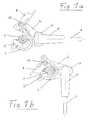
- Fig. 1 shows a side view of an embodiment of an inventive Sensor with plug and cable connection in the open position (a) and in the closed position (b).
- Fig. 2 shows different views (a to e) of the connector and of the joint of a sensor according to FIG. 1.
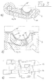
- FIG. 3 shows various views (a to e) of the internal structure of a Housing part of a sensor according to FIG. 2.
- Fig. 2a shows the plug with the snap lock snapping into the air gap 10 8 and the one as a thru axle for the two in the joint Housing parts 2, 2 'serving jack plug pin with the two from each other isolated contact zones 9 and 9 '.
- the one in the two joints shown cylindrical projections and depressions form the Auxiliary joint and the leading edge recognizable in the middle of the air gap 10 on the two housing parts 2, 2 'is used for axial positioning, or to maintain the air gap 10.
- a groove 11 is clearly visible in the housing part 2, into which the hinge axis 12 of the clamping lever 3 is clipped becomes.
- Fig. 3 these are integrated in the housing parts 2, 2 ' Metal parts 13 and 14 clearly visible.
- the measuring element 16 is in contact with the elastic support element 17.
- An electrically conductive elastomer 18 and a thin metal foil 19 conduct the electrical signal from the measuring element to the contact zones of the two Metal parts 13 and 14, the signal with the correct polarity to those in the joints conduct contained contact surfaces of the jack for the jack plug.
- the clamping device also requires one-handed operation, since the Sensor with the clamping device remaining as described simply by must be pushed sideways over the injection line to be measured, after which only the tension lever 3 in the illustration of FIG. 1 of the 1a in the position of Fig. 1b must be pivoted, which can easily be done with the thumb, for example. Also the illustrated and described training of the plug secures and facilitates the operability or manageability of the sensor.
Landscapes
- Physics & Mathematics (AREA)
- General Physics & Mathematics (AREA)
- Electromagnetism (AREA)
- Measuring Fluid Pressure (AREA)
- Measurement Of Length, Angles, Or The Like Using Electric Or Magnetic Means (AREA)
Priority Applications (1)
| Application Number | Priority Date | Filing Date | Title |
|---|---|---|---|
| AT98890028T ATE239212T1 (de) | 1997-03-07 | 1998-02-11 | Sensor zur messung des innendruckes von einspritzleitungen |
Applications Claiming Priority (3)
| Application Number | Priority Date | Filing Date | Title |
|---|---|---|---|
| AT146/97 | 1997-03-07 | ||
| AT0014697U AT2171U1 (de) | 1997-03-07 | 1997-03-07 | Sensor zur messung mechanischer grössen an rohren |
| AT14697 | 1997-03-07 |
Publications (3)
| Publication Number | Publication Date |
|---|---|
| EP0867704A2 true EP0867704A2 (fr) | 1998-09-30 |
| EP0867704A3 EP0867704A3 (fr) | 1999-05-19 |
| EP0867704B1 EP0867704B1 (fr) | 2003-05-02 |
Family
ID=3482759
Family Applications (2)
| Application Number | Title | Priority Date | Filing Date |
|---|---|---|---|
| EP98890028A Expired - Lifetime EP0867704B1 (fr) | 1997-03-07 | 1998-02-11 | Capteur de mesure de la pression interne des tubes d'injection |
| EP98890029A Expired - Lifetime EP0867705B1 (fr) | 1997-03-07 | 1998-02-11 | Capteur de mesure des déformations à la surface d'un corps creux |
Family Applications After (1)
| Application Number | Title | Priority Date | Filing Date |
|---|---|---|---|
| EP98890029A Expired - Lifetime EP0867705B1 (fr) | 1997-03-07 | 1998-02-11 | Capteur de mesure des déformations à la surface d'un corps creux |
Country Status (4)
| Country | Link |
|---|---|
| US (1) | US5942693A (fr) |
| EP (2) | EP0867704B1 (fr) |
| AT (1) | AT2171U1 (fr) |
| ES (2) | ES2199417T3 (fr) |
Cited By (1)
| Publication number | Priority date | Publication date | Assignee | Title |
|---|---|---|---|---|
| EP3696035A1 (fr) * | 2019-02-12 | 2020-08-19 | The Goodyear Tire & Rubber Company | Capteur de pression pour système de freinage et procédé de détérmination de l'efficience de freinage |
Families Citing this family (4)
| Publication number | Priority date | Publication date | Assignee | Title |
|---|---|---|---|---|
| DE10103177A1 (de) * | 2001-01-22 | 2002-08-01 | Balluff Gmbh | Gratprüfungs-Sensorvorrichtung |
| US6879404B2 (en) * | 2001-01-22 | 2005-04-12 | Balluff Gmbh | Device and method for checking bores in or edges on an object of measurement |
| DE102004006680B3 (de) * | 2004-02-09 | 2006-01-12 | Balluff Gmbh | Sensorvorrichtung zur Prüfung von Oberflächen |
| JP2007097116A (ja) * | 2005-08-29 | 2007-04-12 | Sanyo Electric Co Ltd | センサ |
Family Cites Families (8)
| Publication number | Priority date | Publication date | Assignee | Title |
|---|---|---|---|---|
| US2305994A (en) * | 1941-01-31 | 1942-12-22 | Richards Ross | Adjustable clamping device for nozzles or the like |
| US4027536A (en) * | 1975-10-20 | 1977-06-07 | Canadian Patents And Development Limited | Transducer for engine fuel injection monitoring |
| AT354142B (de) * | 1976-11-02 | 1979-12-27 | List Hans | Einrichtung zur elektrischen messung des druckverlaufes in einem rohr |
| DE3439004A1 (de) * | 1984-10-25 | 1986-04-30 | Joachim 5303 Bornheim Gawanka | Halte- oder klemmzange, insbesondere fuer messungen an einspritzleitungen von dieselmotoren |
| US4731556A (en) * | 1987-01-09 | 1988-03-15 | Tello Adams | Electronic bubble detector apparatus |
| JPH02203230A (ja) * | 1989-01-31 | 1990-08-13 | Daikin Ind Ltd | 管内圧力変化検知変換器 |
| US5125801A (en) * | 1990-02-02 | 1992-06-30 | Isco, Inc. | Pumping system |
| DE4020790A1 (de) * | 1990-06-27 | 1992-01-02 | Karl Wunderlich | Rundbuegelbrille |
-
1997
- 1997-03-07 AT AT0014697U patent/AT2171U1/de not_active IP Right Cessation
-
1998
- 1998-02-11 EP EP98890028A patent/EP0867704B1/fr not_active Expired - Lifetime
- 1998-02-11 ES ES98890028T patent/ES2199417T3/es not_active Expired - Lifetime
- 1998-02-11 EP EP98890029A patent/EP0867705B1/fr not_active Expired - Lifetime
- 1998-02-11 ES ES98890029T patent/ES2202792T3/es not_active Expired - Lifetime
- 1998-03-03 US US09/033,602 patent/US5942693A/en not_active Expired - Fee Related
Cited By (1)
| Publication number | Priority date | Publication date | Assignee | Title |
|---|---|---|---|---|
| EP3696035A1 (fr) * | 2019-02-12 | 2020-08-19 | The Goodyear Tire & Rubber Company | Capteur de pression pour système de freinage et procédé de détérmination de l'efficience de freinage |
Also Published As
| Publication number | Publication date |
|---|---|
| ES2199417T3 (es) | 2004-02-16 |
| ES2202792T3 (es) | 2004-04-01 |
| EP0867705A2 (fr) | 1998-09-30 |
| EP0867704A3 (fr) | 1999-05-19 |
| EP0867705B1 (fr) | 2003-06-25 |
| AT2171U1 (de) | 1998-05-25 |
| EP0867705A3 (fr) | 1999-05-19 |
| US5942693A (en) | 1999-08-24 |
| EP0867704B1 (fr) | 2003-05-02 |
Similar Documents
| Publication | Publication Date | Title |
|---|---|---|
| DE19608675C2 (de) | Temperaturmeßvorrichtung mit einer medienführenden Rohrleitung | |
| DE102014008343A1 (de) | Elektrisches Gerät | |
| WO2011083031A1 (fr) | Borne à ressort, en particulier borne frontale | |
| DE3331723A1 (de) | Elektrisches messgeraet mit anschlusskabel | |
| DE102016124370A1 (de) | Sensorvorrichtung sowie Verfahren zum Zusammenbau einer Sensorvorrichtung | |
| DE102018108968A1 (de) | Geschirmtes Steckverbindermodul für einen modularen Industriesteckverbinder | |
| EP0867704B1 (fr) | Capteur de mesure de la pression interne des tubes d'injection | |
| DE102019128821A1 (de) | Klemmeneinrichtung zum Anschließen eines elektrischen Leiters | |
| DE10347111A1 (de) | Integrierte Batteriemessklemme | |
| DE102007004065A1 (de) | Geteilter Federarm | |
| DE2119060C3 (de) | Steckverbindung | |
| DE202015007517U1 (de) | Flanschbaugruppe zur Befestigung eines Kabels an einer Wand mit einer Durchführung | |
| DE4407083C2 (de) | Steckverbindergehäuse und zugehöriger Steckverbinder | |
| DE102010050567A1 (de) | Gehäuse für einen Steckverbinder | |
| DE19846881C2 (de) | Anschlußklemmenbefestigungsaufbau | |
| WO2014090441A1 (fr) | Système de capteur et procédé de fabrication d'un système de capteur | |
| CH647328A5 (de) | Messwertaufnehmer zur messung des inneren druckes in einem rohr. | |
| EP0319633A1 (fr) | Connecteur cinch | |
| DE19646716B4 (de) | Elektrischer Verbinder, insbesondere für Kraftfahrzeuge | |
| DE102023104108A1 (de) | Leiterendkappe | |
| EP4312008A1 (fr) | Agencement de capteurs avec un dispositif de retenue et une unité de capteur de température | |
| EP2808655B1 (fr) | Dispositif de calibrage | |
| DE3811604C1 (en) | Device for the electrical and mechanical connection of electrically conductive cables, especially earth cables, to sheet-metal parts | |
| DE20008214U1 (de) | Verraststift zur Prüfung des mechanischen Sitzes von Elementen in Gehäusen | |
| DE102009049439A1 (de) | Null-Kraft-Steckverbindung |
Legal Events
| Date | Code | Title | Description |
|---|---|---|---|
| PUAI | Public reference made under article 153(3) epc to a published international application that has entered the european phase |
Free format text: ORIGINAL CODE: 0009012 |
|
| AK | Designated contracting states |
Kind code of ref document: A2 Designated state(s): AT BE CH DE ES FR GB IT LI NL SE |
|
| AX | Request for extension of the european patent |
Free format text: AL;LT;LV;MK;RO;SI |
|
| PUAL | Search report despatched |
Free format text: ORIGINAL CODE: 0009013 |
|
| AK | Designated contracting states |
Kind code of ref document: A3 Designated state(s): AT BE CH DE DK ES FI FR GB GR IE IT LI LU MC NL PT SE |
|
| AX | Request for extension of the european patent |
Free format text: AL;LT;LV;MK;RO;SI |
|
| 17P | Request for examination filed |
Effective date: 19990727 |
|
| AKX | Designation fees paid |
Free format text: AT BE CH DE ES FR GB IT LI NL SE |
|
| 17Q | First examination report despatched |
Effective date: 20020313 |
|
| GRAH | Despatch of communication of intention to grant a patent |
Free format text: ORIGINAL CODE: EPIDOS IGRA |
|
| RTI1 | Title (correction) |
Free format text: SENSOR FOR MEASURING THE INTERNAL PRESSURE OF INJECTION TUBES |
|
| GRAH | Despatch of communication of intention to grant a patent |
Free format text: ORIGINAL CODE: EPIDOS IGRA |
|
| GRAA | (expected) grant |
Free format text: ORIGINAL CODE: 0009210 |
|
| AK | Designated contracting states |
Designated state(s): AT BE CH DE ES FR GB IT LI NL SE |
|
| REG | Reference to a national code |
Ref country code: GB Ref legal event code: FG4D Free format text: NOT ENGLISH |
|
| REG | Reference to a national code |
Ref country code: CH Ref legal event code: EP |
|
| GBT | Gb: translation of ep patent filed (gb section 77(6)(a)/1977) |
Effective date: 20030502 |
|
| REG | Reference to a national code |
Ref country code: CH Ref legal event code: NV Representative=s name: ING. HANS LUDESCHER, PATENTABTEILUNG DER SFS GRUPP |
|
| REF | Corresponds to: |
Ref document number: 59808115 Country of ref document: DE Date of ref document: 20030605 Kind code of ref document: P |
|
| REG | Reference to a national code |
Ref country code: SE Ref legal event code: TRGR |
|
| ET | Fr: translation filed | ||
| REG | Reference to a national code |
Ref country code: ES Ref legal event code: FG2A Ref document number: 2199417 Country of ref document: ES Kind code of ref document: T3 |
|
| PLBE | No opposition filed within time limit |
Free format text: ORIGINAL CODE: 0009261 |
|
| STAA | Information on the status of an ep patent application or granted ep patent |
Free format text: STATUS: NO OPPOSITION FILED WITHIN TIME LIMIT |
|
| 26N | No opposition filed |
Effective date: 20040203 |
|
| REG | Reference to a national code |
Ref country code: CH Ref legal event code: PCAR Free format text: ISLER & PEDRAZZINI AG;POSTFACH 1772;8027 ZUERICH (CH) |
|
| PGFP | Annual fee paid to national office [announced via postgrant information from national office to epo] |
Ref country code: ES Payment date: 20080204 Year of fee payment: 11 Ref country code: CH Payment date: 20080215 Year of fee payment: 11 |
|
| PGFP | Annual fee paid to national office [announced via postgrant information from national office to epo] |
Ref country code: SE Payment date: 20080219 Year of fee payment: 11 Ref country code: NL Payment date: 20080131 Year of fee payment: 11 Ref country code: IT Payment date: 20080223 Year of fee payment: 11 Ref country code: GB Payment date: 20080220 Year of fee payment: 11 Ref country code: DE Payment date: 20080204 Year of fee payment: 11 |
|
| PGFP | Annual fee paid to national office [announced via postgrant information from national office to epo] |
Ref country code: AT Payment date: 20080222 Year of fee payment: 11 |
|
| PGFP | Annual fee paid to national office [announced via postgrant information from national office to epo] |
Ref country code: FR Payment date: 20080205 Year of fee payment: 11 |
|
| PGFP | Annual fee paid to national office [announced via postgrant information from national office to epo] |
Ref country code: BE Payment date: 20080327 Year of fee payment: 11 |
|
| BERE | Be: lapsed |
Owner name: *AVL LIST G.M.B.H. Effective date: 20090228 |
|
| REG | Reference to a national code |
Ref country code: CH Ref legal event code: PL |
|
| EUG | Se: european patent has lapsed | ||
| GBPC | Gb: european patent ceased through non-payment of renewal fee |
Effective date: 20090211 |
|
| PG25 | Lapsed in a contracting state [announced via postgrant information from national office to epo] |
Ref country code: LI Free format text: LAPSE BECAUSE OF NON-PAYMENT OF DUE FEES Effective date: 20090228 Ref country code: CH Free format text: LAPSE BECAUSE OF NON-PAYMENT OF DUE FEES Effective date: 20090228 Ref country code: AT Free format text: LAPSE BECAUSE OF NON-PAYMENT OF DUE FEES Effective date: 20090211 |
|
| NLV4 | Nl: lapsed or anulled due to non-payment of the annual fee |
Effective date: 20090901 |
|
| REG | Reference to a national code |
Ref country code: FR Ref legal event code: ST Effective date: 20091030 |
|
| PG25 | Lapsed in a contracting state [announced via postgrant information from national office to epo] |
Ref country code: NL Free format text: LAPSE BECAUSE OF NON-PAYMENT OF DUE FEES Effective date: 20090901 |
|
| PG25 | Lapsed in a contracting state [announced via postgrant information from national office to epo] |
Ref country code: DE Free format text: LAPSE BECAUSE OF NON-PAYMENT OF DUE FEES Effective date: 20090901 |
|
| PG25 | Lapsed in a contracting state [announced via postgrant information from national office to epo] |
Ref country code: BE Free format text: LAPSE BECAUSE OF NON-PAYMENT OF DUE FEES Effective date: 20090228 |
|
| REG | Reference to a national code |
Ref country code: ES Ref legal event code: FD2A Effective date: 20090212 |
|
| PG25 | Lapsed in a contracting state [announced via postgrant information from national office to epo] |
Ref country code: GB Free format text: LAPSE BECAUSE OF NON-PAYMENT OF DUE FEES Effective date: 20090211 Ref country code: FR Free format text: LAPSE BECAUSE OF NON-PAYMENT OF DUE FEES Effective date: 20090302 |
|
| PG25 | Lapsed in a contracting state [announced via postgrant information from national office to epo] |
Ref country code: ES Free format text: LAPSE BECAUSE OF NON-PAYMENT OF DUE FEES Effective date: 20090212 |
|
| PG25 | Lapsed in a contracting state [announced via postgrant information from national office to epo] |
Ref country code: IT Free format text: LAPSE BECAUSE OF NON-PAYMENT OF DUE FEES Effective date: 20090211 |
|
| PG25 | Lapsed in a contracting state [announced via postgrant information from national office to epo] |
Ref country code: SE Free format text: LAPSE BECAUSE OF NON-PAYMENT OF DUE FEES Effective date: 20090212 |