EP0867723A2 - Fibrinogenbestimmungen unter Verwendung von trockenen chemischen Reagenzien die magnetische Teilchen enthalten - Google Patents
Fibrinogenbestimmungen unter Verwendung von trockenen chemischen Reagenzien die magnetische Teilchen enthalten Download PDFInfo
- Publication number
- EP0867723A2 EP0867723A2 EP98201760A EP98201760A EP0867723A2 EP 0867723 A2 EP0867723 A2 EP 0867723A2 EP 98201760 A EP98201760 A EP 98201760A EP 98201760 A EP98201760 A EP 98201760A EP 0867723 A2 EP0867723 A2 EP 0867723A2
- Authority
- EP
- European Patent Office
- Prior art keywords
- separating drum
- drum
- centrifugal separator
- separator according
- separating
- Prior art date
- Legal status (The legal status is an assumption and is not a legal conclusion. Google has not performed a legal analysis and makes no representation as to the accuracy of the status listed.)
- Withdrawn
Links
- 102000008946 Fibrinogen Human genes 0.000 title 1
- 108010049003 Fibrinogen Proteins 0.000 title 1
- 238000003556 assay Methods 0.000 title 1
- 239000003153 chemical reaction reagent Substances 0.000 title 1
- 229940012952 fibrinogen Drugs 0.000 title 1
- 239000006249 magnetic particle Substances 0.000 title 1
- 239000012530 fluid Substances 0.000 claims abstract description 35
- 238000000926 separation method Methods 0.000 claims abstract description 12
- 238000005192 partition Methods 0.000 claims description 22
- 230000002093 peripheral effect Effects 0.000 claims description 5
- XLYOFNOQVPJJNP-UHFFFAOYSA-N water Substances O XLYOFNOQVPJJNP-UHFFFAOYSA-N 0.000 description 53
- 239000007787 solid Substances 0.000 description 36
- 239000007789 gas Substances 0.000 description 9
- 238000012986 modification Methods 0.000 description 8
- 230000004048 modification Effects 0.000 description 8
- 239000007788 liquid Substances 0.000 description 7
- XEEYBQQBJWHFJM-UHFFFAOYSA-N Iron Chemical compound [Fe] XEEYBQQBJWHFJM-UHFFFAOYSA-N 0.000 description 4
- 238000010586 diagram Methods 0.000 description 4
- 238000001914 filtration Methods 0.000 description 4
- 229910052742 iron Inorganic materials 0.000 description 2
- 238000000034 method Methods 0.000 description 2
- 239000000843 powder Substances 0.000 description 2
- 239000010802 sludge Substances 0.000 description 2
- 230000004075 alteration Effects 0.000 description 1
- 239000004568 cement Substances 0.000 description 1
- 239000000919 ceramic Substances 0.000 description 1
- 238000004140 cleaning Methods 0.000 description 1
- 239000003245 coal Substances 0.000 description 1
- 238000004891 communication Methods 0.000 description 1
- 238000010276 construction Methods 0.000 description 1
- 239000004744 fabric Substances 0.000 description 1
- 230000005484 gravity Effects 0.000 description 1
- 239000002184 metal Substances 0.000 description 1
- 229910052751 metal Inorganic materials 0.000 description 1
- 229920001778 nylon Polymers 0.000 description 1
- 239000002245 particle Substances 0.000 description 1
- 238000011144 upstream manufacturing Methods 0.000 description 1
- 239000003643 water by type Substances 0.000 description 1
Images




Classifications
-
- B—PERFORMING OPERATIONS; TRANSPORTING
- B01—PHYSICAL OR CHEMICAL PROCESSES OR APPARATUS IN GENERAL
- B01L—CHEMICAL OR PHYSICAL LABORATORY APPARATUS FOR GENERAL USE
- B01L3/00—Containers or dishes for laboratory use, e.g. laboratory glassware; Droppers
- B01L3/50—Containers for the purpose of retaining a material to be analysed, e.g. test tubes
- B01L3/502—Containers for the purpose of retaining a material to be analysed, e.g. test tubes with fluid transport, e.g. in multi-compartment structures
-
- G—PHYSICS
- G01—MEASURING; TESTING
- G01N—INVESTIGATING OR ANALYSING MATERIALS BY DETERMINING THEIR CHEMICAL OR PHYSICAL PROPERTIES
- G01N33/00—Investigating or analysing materials by specific methods not covered by groups G01N1/00 - G01N31/00
- G01N33/48—Biological material, e.g. blood, urine; Haemocytometers
- G01N33/483—Physical analysis of biological material
- G01N33/487—Physical analysis of biological material of liquid biological material
- G01N33/49—Blood
- G01N33/4905—Determining clotting time of blood
-
- G—PHYSICS
- G01—MEASURING; TESTING
- G01N—INVESTIGATING OR ANALYSING MATERIALS BY DETERMINING THEIR CHEMICAL OR PHYSICAL PROPERTIES
- G01N33/00—Investigating or analysing materials by specific methods not covered by groups G01N1/00 - G01N31/00
- G01N33/48—Biological material, e.g. blood, urine; Haemocytometers
- G01N33/50—Chemical analysis of biological material, e.g. blood, urine; Testing involving biospecific ligand binding methods; Immunological testing
- G01N33/86—Chemical analysis of biological material, e.g. blood, urine; Testing involving biospecific ligand binding methods; Immunological testing involving blood coagulating time or factors, or their receptors
-
- G—PHYSICS
- G01—MEASURING; TESTING
- G01N—INVESTIGATING OR ANALYSING MATERIALS BY DETERMINING THEIR CHEMICAL OR PHYSICAL PROPERTIES
- G01N35/00—Automatic analysis not limited to methods or materials provided for in any single one of groups G01N1/00 - G01N33/00; Handling materials therefor
- G01N35/0098—Automatic analysis not limited to methods or materials provided for in any single one of groups G01N1/00 - G01N33/00; Handling materials therefor involving analyte bound to insoluble magnetic carrier, e.g. using magnetic separation
-
- G—PHYSICS
- G01—MEASURING; TESTING
- G01N—INVESTIGATING OR ANALYSING MATERIALS BY DETERMINING THEIR CHEMICAL OR PHYSICAL PROPERTIES
- G01N2333/00—Assays involving biological materials from specific organisms or of a specific nature
- G01N2333/435—Assays involving biological materials from specific organisms or of a specific nature from animals; from humans
- G01N2333/745—Assays involving non-enzymic blood coagulation factors
- G01N2333/75—Fibrin; Fibrinogen
Definitions
- the present invention relates to centrifugal separators, for example, for use in treating sludge sedimented in rivers, lakes and marshes, soiled waters discharged from iron mills and containing iron particles, coal, etc., and muddy water or effluent resulting from civil engineering work to separate the sludge, muddy water or the like into water and semi- hydrated solids, or for use in separating air containing a powder such as cement into the powder and air.
- the conventional apparatus of any type use a filter, which is liable to clog, therefore requires cleaning or replacement in a short period of time and is cumbersome to use.
- the filter when used, for example, the water and the semihydrated solid matter as separated from each other must be further treated individually so as not to become mixed again, whereas the semihydrated solid matter, which is no longer fluid, is not easy to treat.
- An object of the present invention is to provide a centrifugal separator for separating a fluid containing solid matter into a liquid or gas, and solids reliably without necessitating a cumbersome procedure or treatment.
- the present invention provides a centrifugal separator comprising a separating drum having an opening at at least one end thereof and a vertical axis, revolving means for revolving the separating drum around a vertical line spaced apart by a predetermined distance from the axis of the separating drum, rotating means for rotating the separating drum about its own axis, and feeder means for supplying the fluid to be treated for separation to the separating drum.
- the fluid to be treated When the fluid to be treated is supplied to the separating drum of the separator of the invention, the fluid is separated by the centrifugal force of revolution into solid matter contained in the fluid and a liquid or gas owing to a difference in specific gravity therebetween, and the solid matter adheres to the inner surface of the separating drum, while the liquid or gas forms a layer over the surface of the solid matter and is discharged from the drum through the opening thereof.
- the separating drum rotates about its own axis, permitting the solid matter adhering to the drum inner surface to face toward different directions against the centrifugal force. The solid matter is released from the drum inner surface upon the centrifugal force overcoming the adhesion of the solid matter.
- the fluid containing solids can be reliably separated into the solid matter and a liquid or gas without necessitating a cumbersome procedure or treatment.
- the separating drum has a peripheral wall formed with an aperture for passing therethrough the fluid to be treated, the rotating means being intermittently controllable so as to stop the separating drum with the aperture facing inward, the feeder means being intermittently controllable so as to supply the fluid to be treated to the separating drum as stopped with the aperture facing inward.
- the fluid While the aperture is facing inward, the fluid is efficiently separated into the solid matter and the liquid or gas.
- the aperture When the aperture is directed outward, the solid matter is released from the drum inner surface and centrifugally discharged through the aperture.
- the feeder means may have a hollow supply member disposed inwardly of the separating drum and revolvable along with the separating drum, the supply member having an outlet positionable as opposed to the inwardly facing aperture.
- the fluid to be delivered from the outlet for treatment is forced outward by the centrifugal force of revolution, and the fluid thus forced outward is led into the separating drum without stagnation through the aperture as directed inward.
- the feeder means has a bent fluid supply channel, the fluid will be inadvertently separated at the bent portion. It is then likely that the solids separated off will adhere to the channel wall to clog up the channel, whereas such trouble is avoidable when the fluid is forced out straight.
- an elongated fluid channel can be provided inside the separating drum.
- the fluid channel can be further elongated to achieve an improved separation efficiency if the baffle plates are each in the form of a horizontal plate and are so arranged that each of the baffle plates partially laps over another one of the baffle plates immediately adjacent thereto when viewed axially of the separating drum.
- the revolution of the separating drum causes the fluid to flow upward inside the drum.
- the separating drum may be provided inside thereof with a partition plate positioned at a higher level than a fluid outlet of the feeder means so as to partially occupy the cross section of the separating drum, so that the fluid supplied to the separating drum by one cycle of operation of the feeder means can be prevented by the partition plate from flowing upward owing to the centrifugal force of revolution of the fluid, with the aperture facing inward. This assures reliable separation of the fluid in the separating drum as held out of rotation about its own axis, with the aperture facing inward.
- the separating drum is temporarily held out of rotation about its own axis in the course of movement of the aperture from the inwardly facing position to an outwardly facing position, the fluid can be separated more effectively before discharge through the aperture.
- the separating drum When the separating drum has its opening covered with a filter, the water to be discharged from the drum through its opening is filtered to ensure more effective separation.
- the filter will not be clogged since the solids acting to adhere to the filter are moved centrifugally.
- the separator comprises a hollow body 101, a rotary assembly 102 accommodated in the body 101 and four separating drums 103 each in the form of a vertical hollow cylinder and mounted on the rotary assembly 102.
- the body 101 comprises a vertical tubular trunk wall 111 and a top wall 112 in the form of a flat plate and covering an upper-end opening thereof.
- the trunk wall 111 is provided with a trough 113 positioned inside thereof slightly above the midportion of its height and a discharge pipe 114 in communication with the trough 113.
- a support bar 145 in the form of a horizontal strip extends across a lower-end opening of the trunk wall 111 through the trunk wall axis and is attached to the lower end of the trunk wall 111.
- a lower main bearing 144 is mounted on the upper side of the support bar 145 centrally thereof and coaxially with the trunk wall.
- a main motor 171 facing vertically upward is mounted on the trunk wall outside thereof close to its upper end.
- a main drive sprocket 172 is fixed to the output shaft of the main motor 171.
- the top wall 112 is formed in its central portion with a shaft hole 115 having an upper main bearing 116 fitted therein.
- the rotary assembly 101 comprises a rotary shaft 121 inserted through the bearing 116, a top wall 122 secured directly to the lower end of the shaft 121, and a bottom wall 123 disposed below the top wall 122 at a distance therefrom and connected to the top wall 122 by the separating drums 103.
- a skirt 124 extending into the trough 113 is integral with the outer periphery of the top wall 122.
- the rotary shaft 121 comprises an upper solid shaft portion 131 having a small diameter and a lower hollow shaft portion 132 having a large diameter.
- the solid shaft portion 131 projects upward beyond the upper main bearing 116 and has a main driven sprocket 173 fixed to the projection.
- the sprocket 173 is coupled to the main drive sprocket 172 by a belt 174.
- the hollow shaft portion 132 is supported by the bearing 116.
- a secondary motor 181 Housed in the hollow shaft portion 132 is a secondary motor 181 fixed to the top wall 122 of the rotary assembly.
- the rotary shaft of the motor 181 extends through the top wall 122 to project downward and is supported by a secondary bearing 143.
- a secondary drive sprocket 182 is fixed to the rotary shaft of the secondary motor 181.
- a distribution chamber 141 is fixedly provided on the upper side of the bottom wall 123 centrally thereof.
- the secondary bearing 143 is attached to the upper side of top wall of the chamber 141 with a support member 142 interposed therebetween.
- the bottom plate 123 is supported at the center of its lower side by the lower main bearing 144.
- a bottom wall of the distribution chamber 141 and the bottom wall of the rotary assembly 101 are formed respectively with upper and lower pipe holes 151, 152 in register, and a feed pipe 153 for the water to be treated is inserted through these holes.
- the bottom wall inner periphery defining the upper pipe hole 151 is provided with a vertical sleeve 154.
- the feed pipe 153 is provided at its upper end with a seal ring 155 inverted L-shaped in cross section and covering the sleeve 154.
- the chamber 141 has a peripheral wall formed with four supply pipes 156 arranged radially at equal spacings. The four supply pipes 156 extend toward the axes of the respective four separating drums 103 and each have an outlet 157 at the outer end.
- the separating drum 103 comprises an upwardly flaring portion 161 and a lower straight portion 162.
- the flaring portion 161 is supported by a bearing 163 on the rotary assembly top wall 122, and the straight portion 162 by a bearing 164 on the rotary assembly bottom wall 123.
- the straight portion 132 is formed with a vertically elongated aperture 165 for passing therethrough the fluid to be treated. When facing inward, the aperture 165 is opposed to the outlet 157 of the supply pipe 156.
- the straight portion 162 has a plurality of baffle plates 166 arranged one above another. As shown in greater detail in FIG. 3, the baffle plates 166 are each in the form of a horizontal semicircle. Each baffle plate 166 overlaps another adjacent plate 166 immediately therebelow by a 2/3 portion of the entire area.
- a secondary driven sprocket 183 is secured to the lower end of the flaring portion 161 on the outer side thereof. As seen in FIG. 4, a chain 184 is reeved around the secondary drive sprocket 182 and the secondary driven sprocket 183.
- the rotary assembly 101 rotates about its shaft 121, revolving the separating drums 103 around the axis of the shaft 121.
- the secondary motor 181 when operated, moves the chain 184, whereby the four separating drums 103 are rotated at the same time each about its own axis.
- the speed of revolution of the separating drums 103 is suitably determined according to the properties of the water to be separated.
- the drums 103 are revolved, for example, at a peripheral speed of 500 to 1000 m/min. When the radius of gyration of the revolution is about 400 mm, the speed of revolution is 600 rpm.
- the separating drums 103 are revolved continuously.
- a pump is operated intermittently to supply the water to be separated intermittently, for example, in such manner that the water is supplied for 1 minute, followed by a cessation of supply for 1 minute.
- the separating drums 103 are stopped from rotating about their axes, with the apertures 165 facing inward with respect to the radius of gyration of the revolution.
- the separating drums 103 are rotated once about their axes, whereby the apertures 165 facing inward are turned outward and thereafter directed inward again.
- the separating drums 103 may be initiated into rotation about their axes simultaneously with the discontinuation of supply of the water or upon lapse of a predetermined period of time thereafter.
- the separating drums 103 may be rotated about their axes continuously through 360 degrees, or may be rotated through 180 degrees, then stopped for a predetermined period of time and thereafter rotated in the opposite direction through 180 degrees.
- a modification of the centrifugal separator will be further described with reference to FIGS. 7 to 10.
- the modification basically has the same construction as the centrifugal separator shown in FIGS. 1 to 6.
- FIGS. 7 and 8 show a separating drum 103 having a plurality of partition plates 201 arranged one above another inside the drum.
- the partition plates 201 have the same shape as the baffle plates 166 and are each in the form of a horizontal semicircle. All the partition plates 201 are arranged wholly in register.
- the partition plate 201 occupies the semicircular portion of the drum 103 opposite to the aperture 165, and the straight end of the partition plate 201 opposed to the aperture 165 is orthogonal to the aperture 165.
- the water B to be treated is supplied to the separating drum 103 as held out of rotation about its own axis, with the aperture 165 facing inward.
- the water B is supplied approximately at the level of the lowermost partition plate 201.
- the water B supplied is caused to flow upward over the lowermost partition plate 201 toward another plate 201 thereabove within the drum 103 by the centrifugal force of revolution of the drum, thus passing over the partition plates 201 one after another.
- the amount of the water B to be supplied during one cycle of operation is so determined that the water will not pass over the uppermost partition plate 201 (see FIG. 7).
- the quantity of water supplied by one cycle of operation is collected below the uppermost partition plate 201.
- the water B collected below the uppermost partition plate 201 is completely separated into solid matter D and water W while the separating drum 103 is held at rest before the start of rotation about its own axis as seen in FIG. 7.
- the partition plates 201 are also rotated with the drum 103.
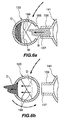
- the straight ends of partition plates 201 become submerged in the separated water W at an angle with respect to the inward or outward direction as indicated in a phantom line in FIG. 9 (b)
- the separated water W starts to flow upward at a point P indicated by a solid spot mark in the drawing, passing over the partition plates 201 one after another, and is discharged from the upper end of the drum 103.
- the drum 103 is rotated through 90 degrees as shown in FIG. 9 (c) and then temporarily held out of rotation. Although the rotation takes a relatively short period of time, the solid matter D and the water W separated from each other differ in adhesion or fluidity and therefore behave differently.
- the water W separated off moves with the rotation of the drum 103 owing to the centrifugal force acting thereon, shifting every moment, and is discharged from the drum 103, whereas the solid matter D tends to remain in position, and therefore remains inside the drum 103, adhering to the inner surface of the drum 103.
- the separating drum 103 With the separating drum 103 held out of rotation after rotating through 90 degrees, the solid matter D is subjected to the centrifugal force, whereby the solid matter D is further separated, and the water W separated off is discharged from the upper end of the drum 103.
- the drum 103 Upon lapse of a predetermined period of time after the drum 103 has been rotated through 90 degrees, the drum 103 resumes rotation about its own axis. When the drum 103 is rotated further through 90 degrees through the resumed rotation as shown in FIG. 9 (d), the aperture 165 faces outward, and the solid matter D centrifugally acted on is discharged through the aperture 165 thus facing outward.
- the rotation of the separating drum 103 may be discontinued when the aperture 165 is brought to the outwardly facing position, but the drum need not be so stopped since the solid matter D is discharged rapidly.
- the drum 103 is continuously further rotated about its own axis, moving the aperture 165 from the outwardly facing position to the inwardly facing position through 180 degrees, the drum 103 finishes one cycle of operation.
- the separating drum 103 may be rotated reversely every time it has been rotated through 180 degrees instead of being rotated through 360 degrees every cycle.
- the present embodiment is so adapted that the water to be treated in the drum is separated as it is wholly collected therein and held at rest.
- the embodiment distinctly differs from the first embodiment.
- the water supplied to the separating drum is subjected to a separating treatment while allowing the water separated off to gradually flow out from the drum upper end at the same time.
- solids are likely to be entrained in the moving water to result in a lower separation efficiency.
- an increased centrifugal force is used to increase the separation capacity, the water separated off is more likely to entrain solids therein, such that an increased centrifugal force fails to improve the separation capacity greatly as expected. Since the water to be treated is held at rest within the separating drum during separation according to the present embodiment, an increased separation capacity is expectable.
- a filter 211 is used in place of the partition plates 201 provided inside the separating drum 103 of FIG. 7.
- the filter 211 is positioned immediately above an aperture 165 for passing the fluid to be treated, and is in the form of a horizontal disk covering the entire upper-end opening of a separating drum 103.
- the filter is made of a so-called wedge wire and has parallel passageways 221. With the aperture 165 facing toward the center of revolution, the lengthwise direction of the passageways 221 is positioned radially of the path of revolution. As shown in greater detail in FIG. 15, the passageways 221 are wedge-shaped in cross section and are about 30 micrometers in minimum width C at the lower ends thereof.
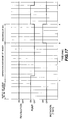
- FIG. 17 is a time chart showing the separating operation described above.
- FIG. 16 shows a modification wherein two filers are used as positioned one above the other.
- the openings or passageways of the two filters 231, 232 are so determined that the lower filter 231 serves for rough filtration, and the upper filter 232 for finishing filtration.
- centrifugal separators may alternatively be used.
- a filter for rough filtration may be used in each separating drum of the upstream separator, with a filter for finishing filtration used in the downstream separator.
- the filter is about 5 to about 50 micrometer in opening size.
- metal netting, fabric, nylon fiber, ceramics, etc. are useful for making the filter.
- the present modification may also have baffle plates or partition plates used in the foregoing modification.
Landscapes
- Health & Medical Sciences (AREA)
- Life Sciences & Earth Sciences (AREA)
- Chemical & Material Sciences (AREA)
- Engineering & Computer Science (AREA)
- Hematology (AREA)
- Biomedical Technology (AREA)
- Immunology (AREA)
- General Health & Medical Sciences (AREA)
- Physics & Mathematics (AREA)
- Analytical Chemistry (AREA)
- Molecular Biology (AREA)
- Urology & Nephrology (AREA)
- Biochemistry (AREA)
- Pathology (AREA)
- General Physics & Mathematics (AREA)
- Food Science & Technology (AREA)
- Medicinal Chemistry (AREA)
- Biophysics (AREA)
- Ecology (AREA)
- Clinical Laboratory Science (AREA)
- Chemical Kinetics & Catalysis (AREA)
- Biotechnology (AREA)
- Cell Biology (AREA)
- Microbiology (AREA)
- Investigating Or Analysing Biological Materials (AREA)
- Measuring Or Testing Involving Enzymes Or Micro-Organisms (AREA)
- Investigating Or Analyzing Materials By The Use Of Magnetic Means (AREA)
- Centrifugal Separators (AREA)
Applications Claiming Priority (3)
| Application Number | Priority Date | Filing Date | Title |
|---|---|---|---|
| US55057090A | 1990-07-10 | 1990-07-10 | |
| US550570 | 1990-07-10 | ||
| EP91914171A EP0538393B1 (de) | 1990-07-10 | 1991-06-28 | Fibrinogenbestimmungen unter verwendung von chemischen trockenreagenzien, die magnetische teilchen enthalten |
Related Parent Applications (1)
| Application Number | Title | Priority Date | Filing Date |
|---|---|---|---|
| EP91914171A Division EP0538393B1 (de) | 1990-07-10 | 1991-06-28 | Fibrinogenbestimmungen unter verwendung von chemischen trockenreagenzien, die magnetische teilchen enthalten |
Publications (2)
| Publication Number | Publication Date |
|---|---|
| EP0867723A2 true EP0867723A2 (de) | 1998-09-30 |
| EP0867723A3 EP0867723A3 (de) | 2003-10-08 |
Family
ID=24197737
Family Applications (2)
| Application Number | Title | Priority Date | Filing Date |
|---|---|---|---|
| EP98201760A Withdrawn EP0867723A3 (de) | 1990-07-10 | 1991-06-28 | Fibrinogenbestimmungen unter Verwendung von trockenen chemischen Reagenzien die magnetische Teilchen enthalten |
| EP91914171A Expired - Lifetime EP0538393B1 (de) | 1990-07-10 | 1991-06-28 | Fibrinogenbestimmungen unter verwendung von chemischen trockenreagenzien, die magnetische teilchen enthalten |
Family Applications After (1)
| Application Number | Title | Priority Date | Filing Date |
|---|---|---|---|
| EP91914171A Expired - Lifetime EP0538393B1 (de) | 1990-07-10 | 1991-06-28 | Fibrinogenbestimmungen unter verwendung von chemischen trockenreagenzien, die magnetische teilchen enthalten |
Country Status (10)
| Country | Link |
|---|---|
| US (1) | US5350676A (de) |
| EP (2) | EP0867723A3 (de) |
| JP (1) | JP2649608B2 (de) |
| AT (1) | ATE174633T1 (de) |
| AU (1) | AU660624B2 (de) |
| CA (1) | CA2087033C (de) |
| DE (1) | DE69130644T2 (de) |
| ES (1) | ES2128321T3 (de) |
| TW (1) | TW221493B (de) |
| WO (1) | WO1992001065A1 (de) |
Families Citing this family (70)
| Publication number | Priority date | Publication date | Assignee | Title |
|---|---|---|---|---|
| US6114135A (en) * | 1991-11-08 | 2000-09-05 | Goldstein; Sheldon | Multiple coagulation test system and method of using a multiple coagulation test system |
| DK203191D0 (da) * | 1991-12-19 | 1991-12-19 | Novo Nordisk As | Fremgangsmaade og apparat til bestemmelse af relevante blodparametre |
| US5443959A (en) * | 1992-09-09 | 1995-08-22 | Tokuyama Corporation | Method of assaying fibrinogen, dry reagent therefor, and process for the preparation thereof |
| EP0587398B1 (de) * | 1992-09-09 | 1998-01-14 | Tokuyama Corporation | Methode zur Bestimmung von Fibrinogen, trockenes Reagens hierfür und Verfahren zur Herstellung desselben |
| US5605798A (en) | 1993-01-07 | 1997-02-25 | Sequenom, Inc. | DNA diagnostic based on mass spectrometry |
| KR100305306B1 (ko) * | 1993-02-17 | 2001-11-22 | 존 펑크하우저 | 건식화학캐스케이드면역분석법및친화도분석법 |
| US5670329A (en) * | 1993-05-28 | 1997-09-23 | Cardiovascular Diagnostics, Inc. | Method and analytical system for performing fibrinogen assays accurately, rapidly and simply using a rotating magnetic field |
| US5526111A (en) * | 1993-08-31 | 1996-06-11 | Boehringer Mannheim Corporation | Method and apparatus for calculating a coagulation characteristic of a sample of blood a blood fraction or a control |
| EP0720439A4 (de) * | 1993-08-31 | 1997-09-24 | Boehringer Mannheim Corp | Stromversorgungssteuerung und kontrolle für medizinisches instrument |
| US5841023A (en) * | 1993-08-31 | 1998-11-24 | Boehringer Mannheim Corporation | Magnet for medical instrument |
| US5522255A (en) | 1993-08-31 | 1996-06-04 | Boehringer Mannheim Corporation | Fluid dose, flow and coagulation sensor for medical instrument |
| US5502651A (en) * | 1994-05-02 | 1996-03-26 | Jackson; R. David | Potentiophotometric fibrinogen determination |
| US5504011A (en) * | 1994-10-21 | 1996-04-02 | International Technidyne Corporation | Portable test apparatus and associated method of performing a blood coagulation test |
| AU689143B2 (en) * | 1994-12-02 | 1998-03-26 | Cardiovascular Diagnostics, Inc. | Improved method and analytical system for performing fibrinogen assays accurately, rapidly and simply |
| US5567596A (en) * | 1994-12-29 | 1996-10-22 | Research Foundation Of State University Of New York | Rapid assay of activators and inhibitors of clotting |
| US5830655A (en) | 1995-05-22 | 1998-11-03 | Sri International | Oligonucleotide sizing using cleavable primers |
| AU2069597A (en) * | 1996-03-04 | 1997-09-22 | Genetrace Systems, Inc. | Methods of screening nucleic acids using mass spectrometry |
| US5965363A (en) | 1996-09-19 | 1999-10-12 | Genetrace Systems Inc. | Methods of preparing nucleic acids for mass spectrometric analysis |
| US7285422B1 (en) | 1997-01-23 | 2007-10-23 | Sequenom, Inc. | Systems and methods for preparing and analyzing low volume analyte array elements |
| EP1460083B1 (de) | 1996-11-06 | 2006-01-18 | Sequenom, Inc. | Verfahren zur Analyse und Vorrichtung |
| EP0954612A2 (de) | 1996-11-06 | 1999-11-10 | Sequenom, Inc. | Dna-diagnostik mittels massenspektrometrie |
| CA2274587A1 (en) | 1996-12-10 | 1998-06-18 | Genetrace Systems Inc. | Releasable nonvolatile mass-label molecules |
| US5998224A (en) * | 1997-05-16 | 1999-12-07 | Abbott Laboratories | Magnetically assisted binding assays utilizing a magnetically responsive reagent |
| US6046051A (en) * | 1997-06-27 | 2000-04-04 | Hemosense, Inc. | Method and device for measuring blood coagulation or lysis by viscosity changes |
| HU222809B1 (hu) | 1997-10-03 | 2003-10-28 | 77 Elektronika Műszeripari Kft. | Eljárás és készülék kémiai összetevőnek anyagmintából, különösen vér glükóztartalmának vérmintából történő meghatározásához |
| US6165795A (en) * | 1998-06-25 | 2000-12-26 | Cardiovascular Diagnostics, Inc. | Methods for performing fibrinogen assays using dry chemical reagents containing ecarin and magnetic particles |
| US6417004B1 (en) * | 1999-04-29 | 2002-07-09 | Helena Laboratories Corporation | Enhancing clot detection in activated clotting time and other fibrin endpoint based tests |
| US6294342B1 (en) | 1999-09-29 | 2001-09-25 | Abbott Laboratories | Magnetically assisted binding assays utilizing a magnetically responsive reagent |
| KR20030014219A (ko) * | 2000-05-09 | 2003-02-15 | 파마네틱스 인코포레이티드 | 혈소판 기능 측정법 및 이에 사용하는 시약 |
| AU2001268468A1 (en) | 2000-06-13 | 2001-12-24 | The Trustees Of Boston University | Use of nucleotide analogs in the analysis of oligonucleotide mixtures and in highly multiplexed nucleic acid sequencing |
| KR100649342B1 (ko) | 2000-10-30 | 2006-11-27 | 시쿼넘, 인코포레이티드 | 기판 상으로 서브마이크로리터 볼륨들을 전달하기 위한 방법 및 장치 |
| US6759009B2 (en) | 2001-05-04 | 2004-07-06 | Portascience Incorporated | Method and device for clotting time assay |
| DE10140699A1 (de) * | 2001-08-24 | 2003-03-13 | Roche Diagnostics Gmbh | Anordnung und Verfahren zur Untersuchung der Fließfähigkeit einer physiologischen Flüssigprobe |
| US6902904B2 (en) * | 2001-08-27 | 2005-06-07 | Pharmanetics Incorporated | Coagulation assay reagents containing lanthanides |
| US6680177B2 (en) * | 2001-12-07 | 2004-01-20 | Cardiovascular Diagnostics, Inc. | Low molecular weight heparin assay, system and reagent therefor |
| DE10325173B4 (de) * | 2003-06-04 | 2007-11-08 | Stief, Thomas, Dr.med. | Nachweisverfahren für Fibrinogen und/oder Fibrinogen-Derivate |
| GB0313015D0 (en) * | 2003-06-06 | 2003-07-09 | Hall Effect Technologies Ltd | Method and device for analysing a liquid |
| EP1544596B1 (de) * | 2003-12-17 | 2016-11-23 | Boehringer Ingelheim microParts GmbH | Verfahren und Vorrichtung zur Bestimmung der Viskosität |
| US7439069B2 (en) | 2004-02-27 | 2008-10-21 | Nippoldt Douglas D | Blood coagulation test cartridge, system, and method |
| US7422905B2 (en) | 2004-02-27 | 2008-09-09 | Medtronic, Inc. | Blood coagulation test cartridge, system, and method |
| US7399637B2 (en) | 2004-04-19 | 2008-07-15 | Medtronic, Inc. | Blood coagulation test cartridge, system, and method |
| US9267167B2 (en) | 2004-06-28 | 2016-02-23 | Becton, Dickinson And Company | Dissolvable films and methods including the same |
| WO2006020187A2 (en) * | 2004-07-16 | 2006-02-23 | The University Of North Carolina At Chapel Hill | Methods, systems and computer program products for full spectrum projection |
| US20060024776A1 (en) * | 2004-08-02 | 2006-02-02 | Mcmillian Ray | Magnetic particle capture of whole intact organisms from clinical samples |
| WO2006137334A1 (ja) * | 2005-06-23 | 2006-12-28 | Arkray, Inc. | 分析用具 |
| GB2438669A (en) * | 2006-03-07 | 2007-12-05 | Inverness Medical Switzerland | Sensing apparatus having a pair of coils and an oscillating member |
| WO2008103430A2 (en) * | 2007-02-22 | 2008-08-28 | The University Of North Carolina At Chapel Hill | Methods and systems for multiforce high throughput screening |
| US20080297169A1 (en) * | 2007-05-31 | 2008-12-04 | Greenquist Alfred C | Particle Fraction Determination of A Sample |
| US20090180931A1 (en) | 2007-09-17 | 2009-07-16 | Sequenom, Inc. | Integrated robotic sample transfer device |
| WO2009050643A1 (en) | 2007-10-16 | 2009-04-23 | Koninklijke Philips Electronics N.V. | Estimation of diagnostic markers |
| WO2009055940A1 (en) * | 2007-11-02 | 2009-05-07 | Verano Financial Ltd. | Method and apparatus for monitoring spatial fibrin clot formation |
| CN101983338B (zh) * | 2008-03-31 | 2015-03-04 | 希森美康株式会社 | 凝血分析仪、凝血分析方法及计算机程序 |
| WO2009137095A2 (en) | 2008-05-08 | 2009-11-12 | The Johns Hopkins University | Compositions and methods for modulating an immune response |
| RU2530716C2 (ru) | 2008-12-22 | 2014-10-10 | Конинклейке Филипс Электроникс Н.В. | Анализ тропонина i с применением магнитных меток |
| JP5816613B2 (ja) | 2009-04-23 | 2015-11-18 | ダブリン シティ ユニバーシティ | 凝固をモニタするための側方流動分析装置及びその方法 |
| JP5511949B2 (ja) | 2009-06-25 | 2014-06-04 | ザ ユニバーシティ オブ ノース カロライナ アット チャペル ヒル | 体液レオロジーを評価するための、作動され表面に付着したポストを使用するための方法及びシステム |
| DE102011001952B8 (de) * | 2011-04-11 | 2012-12-20 | Johann-Wolfgang-Goethe Universität Frankfurt am Main | Vorrichtung und Verfahren zur Bestimmung der Koagulationszeit von Blut |
| US8772039B2 (en) * | 2011-05-26 | 2014-07-08 | The General Hospital Corporation | Optical thromboelastography system and method for evaluation of blood coagulation metrics |
| WO2014085804A1 (en) | 2012-11-30 | 2014-06-05 | The University Of North Carolina At Chapel Hill | Methods, systems, and computer readable media for determining physical properties of a specimen in a portable point of care diagnostic device |
| US11172888B2 (en) | 2012-12-19 | 2021-11-16 | The General Hospital Corporation | Optical blood-coagulation sensor |
| TWI499779B (zh) | 2013-07-04 | 2015-09-11 | Ind Tech Res Inst | 檢測晶片及其使用方法 |
| US10823743B1 (en) * | 2013-10-28 | 2020-11-03 | Ifirst Medical Technologies, Inc. | Methods of measuring coagulation of a biological sample |
| KR20160073016A (ko) | 2014-12-16 | 2016-06-24 | 삼성전자주식회사 | 광학분석용 구조체 및 광학분석용 구조체 제조용 잉크 조성물 |
| KR102094241B1 (ko) * | 2018-04-17 | 2020-03-27 | 고려대학교산학협력단 | 혈액 샘플 내 피브리노겐 농도 측정 방법 및 이를 위한 나노입자 |
| WO2020051761A1 (zh) * | 2018-09-11 | 2020-03-19 | 深圳迈瑞生物医疗电子股份有限公司 | 凝血分析仪及其检测样本的方法、存储介质 |
| CN109856410A (zh) * | 2019-02-15 | 2019-06-07 | 王振华 | 一种血凝测试装置 |
| WO2021154995A1 (en) | 2020-01-29 | 2021-08-05 | Ifirst Medical Technologies, Inc. | Medical analyzer and diagnostic sample profiler |
| JP7529446B2 (ja) * | 2020-06-05 | 2024-08-06 | 株式会社エイアンドティー | フィブリノゲン測定方法 |
| CN113976192B (zh) * | 2021-08-23 | 2023-08-15 | 上海汉原生物科技有限公司 | 微球标记微流控芯片以及微球蛋白标记方法 |
| US20230314405A1 (en) * | 2022-03-30 | 2023-10-05 | Instrumentation Laboratory Company | Clinical decision support system |
Family Cites Families (6)
| Publication number | Priority date | Publication date | Assignee | Title |
|---|---|---|---|---|
| BE792113A (fr) * | 1971-12-13 | 1973-05-30 | Technicon Instr | Melangeur de liquides contenant des particules magnetiques |
| US3861197A (en) * | 1973-06-29 | 1975-01-21 | Technicon Instr | Method and apparatus for determining the viscosity of a liquid sample |
| US4756884A (en) * | 1985-08-05 | 1988-07-12 | Biotrack, Inc. | Capillary flow device |
| US4849340A (en) * | 1987-04-03 | 1989-07-18 | Cardiovascular Diagnostics, Inc. | Reaction system element and method for performing prothrombin time assay |
| US5110727A (en) * | 1987-04-03 | 1992-05-05 | Cardiovascular Diagnostics, Inc. | Method for performing coagulation assays accurately, rapidly and simply, using dry chemical reagents and paramagnetic particles |
| US5156974A (en) * | 1988-05-27 | 1992-10-20 | Biodata Corporation | Method for determining the fibrinogen level of a blood sample |
-
1990
- 1990-07-31 TW TW079106328A patent/TW221493B/zh active
-
1991
- 1991-06-28 DE DE69130644T patent/DE69130644T2/de not_active Expired - Fee Related
- 1991-06-28 WO PCT/US1991/004472 patent/WO1992001065A1/en not_active Ceased
- 1991-06-28 AT AT91914171T patent/ATE174633T1/de not_active IP Right Cessation
- 1991-06-28 CA CA002087033A patent/CA2087033C/en not_active Expired - Fee Related
- 1991-06-28 EP EP98201760A patent/EP0867723A3/de not_active Withdrawn
- 1991-06-28 JP JP3513307A patent/JP2649608B2/ja not_active Expired - Fee Related
- 1991-06-28 AU AU83119/91A patent/AU660624B2/en not_active Ceased
- 1991-06-28 EP EP91914171A patent/EP0538393B1/de not_active Expired - Lifetime
- 1991-06-28 ES ES91914171T patent/ES2128321T3/es not_active Expired - Lifetime
-
1993
- 1993-05-17 US US08/062,334 patent/US5350676A/en not_active Expired - Fee Related
Also Published As
| Publication number | Publication date |
|---|---|
| EP0538393A1 (de) | 1993-04-28 |
| ATE174633T1 (de) | 1999-01-15 |
| ES2128321T3 (es) | 1999-05-16 |
| JPH06500463A (ja) | 1994-01-20 |
| JP2649608B2 (ja) | 1997-09-03 |
| EP0867723A3 (de) | 2003-10-08 |
| AU660624B2 (en) | 1995-07-06 |
| DE69130644D1 (de) | 1999-01-28 |
| EP0538393B1 (de) | 1998-12-16 |
| CA2087033A1 (en) | 1992-01-11 |
| AU8311991A (en) | 1992-02-04 |
| TW221493B (de) | 1994-03-01 |
| CA2087033C (en) | 2003-06-24 |
| EP0538393A4 (de) | 1994-01-26 |
| DE69130644T2 (de) | 1999-07-29 |
| WO1992001065A1 (en) | 1992-01-23 |
| US5350676A (en) | 1994-09-27 |
Similar Documents
| Publication | Publication Date | Title |
|---|---|---|
| US3899414A (en) | Drilling mud separation system | |
| US6868973B1 (en) | Drum type refining or washing apparatus | |
| JPS6116515B2 (de) | ||
| US4981219A (en) | Apparatus and method for separating intermixed particles of differing densities | |
| JP2015202448A (ja) | 固液分離装置 | |
| AU5756796A (en) | Centrifugal concentrator | |
| EP0882511A2 (de) | Zentrifugalabscheider | |
| FI57705B (fi) | Hydraulisk klassificerare | |
| SE463425B (sv) | Avvattningsanordning | |
| US6109450A (en) | Apparatus for separating unwanted contaminants from fibrous slurry | |
| RU2087200C1 (ru) | Центробежный сепаратор периодического действия | |
| US3276591A (en) | Apparatus for treating suspensions | |
| JP2003534912A (ja) | 篩システムによる遠心機およびその作動方法 | |
| EP0258012A2 (de) | Flüssig-Fest-Zentrifugalseparator | |
| JPH06190225A (ja) | 流動する液体中の懸濁物質を分離する方法及び装置 | |
| RU2094122C1 (ru) | Центробежный сепаратор | |
| US3884806A (en) | Method and apparatus for centrifugally regenerative filtration | |
| US2488746A (en) | Centrifuge with centrifugally flushed filter | |
| SU1567117A3 (ru) | Сгуститель | |
| GB2121325A (en) | Cleaning centrifuge | |
| EP0069729A1 (de) | Rückgewinnungssystem für industrielle kühlflüssigkeiten | |
| SE503981C2 (sv) | Anordning för avskiljning av icke önskvärda partiklar från en suspensionsström | |
| JPH10165841A (ja) | 遠心分離装置 | |
| AU5185798A (en) | Centrifugal separator with injection of fluidizing liquid between non-fluidized recesses | |
| RU2462291C1 (ru) | Центробежный сепаратор |
Legal Events
| Date | Code | Title | Description |
|---|---|---|---|
| PUAI | Public reference made under article 153(3) epc to a published international application that has entered the european phase |
Free format text: ORIGINAL CODE: 0009012 |
|
| AC | Divisional application: reference to earlier application |
Ref document number: 538393 Country of ref document: EP |
|
| AK | Designated contracting states |
Kind code of ref document: A2 Designated state(s): AT BE CH DE DK ES FR GB GR IT LI LU NL SE |
|
| K1C3 | Correction of patent application (complete document) published |
Effective date: 19980930 |
|
| PUAL | Search report despatched |
Free format text: ORIGINAL CODE: 0009013 |
|
| AK | Designated contracting states |
Kind code of ref document: A3 Designated state(s): AT BE CH DE DK ES FR GB GR IT LI LU NL SE |
|
| 17P | Request for examination filed |
Effective date: 20040407 |
|
| 17Q | First examination report despatched |
Effective date: 20040924 |
|
| STAA | Information on the status of an ep patent application or granted ep patent |
Free format text: STATUS: THE APPLICATION IS DEEMED TO BE WITHDRAWN |
|
| 18D | Application deemed to be withdrawn |
Effective date: 20050424 |