EP0868609B1 - Pompe hydraulique a bruit reduit pourvue d'un dispositif de synchronisation de clapet - Google Patents
Pompe hydraulique a bruit reduit pourvue d'un dispositif de synchronisation de clapet Download PDFInfo
- Publication number
- EP0868609B1 EP0868609B1 EP96944510A EP96944510A EP0868609B1 EP 0868609 B1 EP0868609 B1 EP 0868609B1 EP 96944510 A EP96944510 A EP 96944510A EP 96944510 A EP96944510 A EP 96944510A EP 0868609 B1 EP0868609 B1 EP 0868609B1
- Authority
- EP
- European Patent Office
- Prior art keywords
- check valve
- pump
- outlet
- check
- assembly
- Prior art date
- Legal status (The legal status is an assumption and is not a legal conclusion. Google has not performed a legal analysis and makes no representation as to the accuracy of the status listed.)
- Expired - Lifetime
Links
- 239000012530 fluid Substances 0.000 claims description 45
- 238000005086 pumping Methods 0.000 claims description 22
- 238000006073 displacement reaction Methods 0.000 claims description 11
- 238000004891 communication Methods 0.000 claims description 3
- 230000008859 change Effects 0.000 description 6
- 230000010355 oscillation Effects 0.000 description 6
- 230000033001 locomotion Effects 0.000 description 4
- 230000007704 transition Effects 0.000 description 4
- 210000003734 kidney Anatomy 0.000 description 3
- 238000007599 discharging Methods 0.000 description 2
- 239000007788 liquid Substances 0.000 description 2
- 238000005457 optimization Methods 0.000 description 2
- 230000006835 compression Effects 0.000 description 1
- 238000007906 compression Methods 0.000 description 1
- 238000001746 injection moulding Methods 0.000 description 1
- 239000000463 material Substances 0.000 description 1
- 230000013011 mating Effects 0.000 description 1
- 238000000034 method Methods 0.000 description 1
- 238000012986 modification Methods 0.000 description 1
- 230000004048 modification Effects 0.000 description 1
- 238000012354 overpressurization Methods 0.000 description 1
- 230000035939 shock Effects 0.000 description 1
- 230000003595 spectral effect Effects 0.000 description 1
Images






Classifications
-
- F—MECHANICAL ENGINEERING; LIGHTING; HEATING; WEAPONS; BLASTING
- F04—POSITIVE - DISPLACEMENT MACHINES FOR LIQUIDS; PUMPS FOR LIQUIDS OR ELASTIC FLUIDS
- F04B—POSITIVE-DISPLACEMENT MACHINES FOR LIQUIDS; PUMPS
- F04B1/00—Multi-cylinder machines or pumps characterised by number or arrangement of cylinders
- F04B1/12—Multi-cylinder machines or pumps characterised by number or arrangement of cylinders having cylinder axes coaxial with, or parallel or inclined to, main shaft axis
- F04B1/20—Multi-cylinder machines or pumps characterised by number or arrangement of cylinders having cylinder axes coaxial with, or parallel or inclined to, main shaft axis having rotary cylinder block
- F04B1/2014—Details or component parts
- F04B1/2042—Valves
Definitions
- the present invention is directed to the field of hydraulic pumps, particularly positive displacement pumps such as axial piston pumps and vane pumps.
- Hydraulic systems are widely used in many power and motion control applications and offer numerous advantages such as high power density, robust performance and relatively low cost.
- hydraulic systems are often noisy. This is often a result of noise produced by the hydraulic pump.
- Increasingly stringent regulations limiting overall noise in the workplace have increased the need for reducing the noise generated by hydraulic pumps.
- a standard axial piston pump and its operation is shown in Figs. 1A and 1B.
- a plurality of pistons 10 are provided for receiving hydraulic fluid.
- the pistons 10 are mounted in a cylinder block 12 which is rotated by a drive shaft 14 and driven by a power source (not shown).
- the pistons 10 are alternately stroked in and out by a yoke 16 which is inclined at a particular angle, typically about 17.5° at full stroke.
- the pistons are in fluid communication with respective inlet and outlet ports 24, 26 which supply and receive the hydraulic fluid.
- the piston 10 retracts, expanding the pumping chamber 18. Fluid is drawn in to the pumping chamber 18 from inlet port 24 through valve block 28.
- the pistons 10 reach their maximum extent at bottom dead center (BDC), after which the pistons 10 extend, collapsing the pumping chamber 18 and thereby discharging the fluid through the valve block 28 into the outlet port 26.
- BDC bottom dead center
- the cylinder block 12 is fluidly connected to the inlet and outlet ports 24, 26 through a valve plate 30 which includes respective inlet and outlet kidney slots 32, 34.
- a valve plate 30 which includes respective inlet and outlet kidney slots 32, 34.
- the structure and operation of a typical valve plate 30 is shown in Figs. 2A and 2B.
- the rotating pistons 10 draw in hydraulic fluid through the inlet kidney slot 32, the fluid being typically supplied at atmospheric pressure.
- the pumping chamber 18 After the pumping chamber 18 is closed to the inlet 32, it passes BDC, compressing the fluid and discharging the fluid into the outlet kidney slot 34 where it is supplied to the hydraulic system.
- Such valve plates are advantageous since a variety of valve plates can be interchangeably used to optimize pump operation for a number of different operating conditions.
- the chamber pressure of the hydraulic pump should be matched to the system pressure.
- Hydraulic pumps can be driven over a wide range of speeds. As the shaft 14 rotates faster, the pistons 10 displace a greater volume of fluid per unit time.
- flow can also be varied by stroke, i.e., the length of piston displacement as determined by the angle of the yoke 16.
- the yoke 16 can be varied between maximum pitch (to produce maximum piston displacement) and a pitch of zero (to produce zero piston displacement) using the control piston 20 and the bias piston 22.
- the piston displacement corresponds to the volume of fluid displaced, hence the rate of flow.
- the third factor that affects pressure within the pumping chamber is hydraulic fluid temperature variation, since it changes the bulk modulus (fluid stiffness) of the fluid.
- yoke flutter Another source of pump housing vibration is "yoke flutter", an oscillation in the yoke 16 produced by the reciprocating forces of the pistons 10 against the yoke 16.
- each piston 10 applies a moment to the yoke 16 which slightly alters the yoke's pitch and subsequently the stroke of the pistons.
- Yoke oscillations produce a "pitching" which causes deflections in the pump housing, thereby generating noise.
- the level of noise is proportional to the magnitude of the change in the yoke moment.
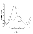
- the curve 40 shows that for a typical yoke arrangement, the moment can vary by several hundred Nm (inch-pounds) as a function of chamber angle past bottom dead center (where pumping chamber volume is maximum).
- the curve 40 also repeats itself over every 360/n degrees of chamber angle, where n is the number of pistons.
- a preferable method of reducing noise is to reduce the alternating forces that produce the deflections in the pump components and the oscillations of the yoke. This is done by using a metering groove 38, as shown in Figs. 2A and 2B.
- the metering groove extends into the transition region around BDC and creates a fluid passageway between the piston chamber and the outlet 34.
- the piston chamber 18 is "mechanically” pressurized by the forward motion of the pumping piston.
- the pumping chamber is also “hydraulically” pressurized.
- the pressure differential between the chamber and the system is equalized, reducing overshoot and the noise produced thereby.
- the pressure profile shape is controlled by the shape of the metering groove 38.
- the design of the groove is referred to as "pump timing".
- pump timing In addition to overshoots and undershoots as a source of noise, a high rate of pressure change is sufficient to provide a large amount of energy that tends to excite structural resonances, thereby producing noise. Thus, it is also important to control the rates of pressurization so as to control the spectral content of the forcing functions exiting resonances in the pump components.
- the pump timing can be designed to control pressurization so as to produce a minimum rate of pressure change in addition to a minimum overshoot.
- pump timing design can only be “tuned” for a particular pump speed, system pressure and pump stroke. Since these quantities are variables, any low noise pump design must necessarily be a compromise, since a pump must be capable of operating over a wide range of conditions.
- a pump which includes two passageways.
- the first leads from a low pressure port to an opening in one of two bridge portions formed between the low pressure port and a high pressure port.
- the second passageway leads from the high pressure port to an opening in the second brigde portion.
- First and second non-return valve means being respectively provided in the first and second passageway.
- the first non-return valve means is so constructed and arranged in the first passageway as to prevent flow of liquid in a direction towards the flow pressure port, while the second non-return valve means is so constructed and arranged in the second passageway as to prevent flow of liquid in a direction away from the high pressure port.
- the hydraulic pump of the present invention which includes a flow generation assembly including at least one pumping chamber for creating positive displacement of hydraulic fluid into a hydraulic system.
- the flow generation assembly can be the components of piston pump, a vane pump, or any other type of positive displacement hydraulic pump.
- a valve plate is in fluid communication with said flow generation assembly, wherein said valve plate defines an inlet for admitting hydraulic fluid and also an outlet for receiving discharged hydraulic fluid.
- a check valve assembly is received within said valve plate for establishing a fluid passageway between the flow generation assembly and the outlet. The check valve assembly reduces the pressure overshoot between the flow generation assembly and the outlet.
- the check valve assembly further comprises a check valve having a plurality of apertures, said apertures being sized so as to permit a predetermined flow of fluid through the check valve assembly, whereby the check valve assembly reduces noise generated by the pressure differential between the flow generation assembly and the outlet.
- Figs. 1A and 1B are sectional views respectively illustrating the configuration and operation of a standard axial hydraulic piston pump.
- Figs. 2A and 2B are respectively frontal and oblique views showing the configuration and operation of a standard hydraulic valve plate.
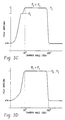
- Figs. 3A, 3B, 3C and 3D are graphs depicting various pressure profiles that occur between the piston chamber and the hydraulic system in a standard hydraulic pump, measured as a function of chamber angle where bottom dead center equals zero.
- Fig. 4 is a graph depicting the yoke moments of a standard hydraulic pump and the same pump with a check valve as according to the present invention, measured as a function of chamber angle past bottom dead center.
- Fig. 5 is a frontal view showing a valve plate with a check valve assembly as according to the present invention.
- Fig. 6 is an oblique sectional view detailing the check valve timing device according to a first embodiment of the present invention.
- Fig. 7 is a frontal and side view showing the check valve as according to the present invention.
- Figs. 8A and 8B are respectively sectional and exploded sectional views detailing a valve plate with the check valve assembly according to a second embodiment of the present invention.
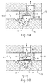
- Figs. 9A, 9B, 9C and 9D are side sectional views illustrating the operation a hydraulic pump including the check valve timing device according to the first embodiment of the present invention.
- Fig. 10 is a graph which compares pressure profiles for a pump respectively with or without the check valve timing device according to the present invention.
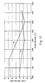
- Fig. 11 is a graph comparing the sound profiles as a function of system pressure for a hydraulic pump and the same pump including the check valve timing device according to the present invention.
- FIGs. 5 and 6 illustrate a valve plate 50 as according to a first embodiment of the present invention having a check valve assembly 56 with a communicating hole 58 located in the transition region in between the inlet 52 and the outlet 54 just past bottom dead center.
- the communicating hole 58 is fluidly connected to a check valve seat 60, formed on the bottom of the valve plate 50, in order to receive a check valve 62.
- the check valve seat 60 is substantially sized to be slightly larger than the check valve 62 so as to permit reciprocating movement of the check valve 62 within the seat.
- the check valve seat 60 is opened to a check valve pocket 64 formed on a mating surface of the valve block 66 of the hydraulic pump.
- the check valve pocket 64 is made smaller than the check valve seat 60 so as to permit the check valve 62 to rest along the surface of the valve block 66.
- a fluid passageway 68 is formed in the valve block 66, fluidly connecting the check valve pocket 64 to the outlet 54.
- the check valve assembly 56 defines a controllable fluid passage for equalizing fluid pressures between the piston in the transition region and the outlet 54, thus reducing noise levels during operation.
- the check valve 62 is preferably a thin disc having a plurality of apertures 70 located concentrically around an aperture 72 at the center of the disc. As will be shown, these respective apertures 70, 72 are selectively sized so as to establish a desired flow rate through the check valve assembly 56.
- Figs. 9A-D The operation of the hydraulic pump with the check valve assembly 56 of the present invention is shown especially by Figs. 9A-D.
- the pumping chamber opens to the communicating hole 58 as soon as it closes to the inlet 52. Since the chamber is typically at a lower chamber pressure at this position than the outlet 54, the hydraulic fluid flows through the passageway 68 and presses the check valve 62 against the valve plate 50. At this point, the concentric apertures 70 are blocked and fluid only flows through the central aperture 72, through the communicating hole 58, to pressurize the pumping chamber.
- the fluid becomes mechanically compressed. If the chamber pressure exceeds the system pressure (as shown in Fig. 9B) the chamber fluid presses the check valve 62 downward, permitting the fluid to flow through all of the apertures 70, 72 into the check valve pocket 64. In this way, a large quantity of fluid is permitted to flow toward the outlet 54, equalizing the chamber pressure to the system pressure at a steady rate, reducing pressure overshoot and the other rapid changes in pressure that create noise-generating deformations of the pump components and the "pitching" from the oscillation of the yoke along its bearing axis.
- the present check valve assembly 56 continues to pressurize the piston chamber in the event that chamber pressure remains lower than system pressure during mechanical compression of the fluid. Since only the central aperture 72 is opened to the communicating hole 58, only a small amount of fluid is permitted to pass, thus metering the rate that the cylinder is pressurized. In any event, the present check valve assembly reduces overshoots so that the system pressure and chamber pressure are substantially equalized at the point of piston discharge, as shown in Fig. 9D.
- the apertures 70, 72 in the check valve 62 can be sized to optimize pump timing for a particular set of pump operating conditions. As shown in Fig. 10, the pressure curves 74 of a pump using an appropriately selected check valve have significantly reduced overshoots over a variety of system conditions as compared with the pressure curves 76 of a pump wihtout the check valve. Applicant has observed that a 0,6 mm (0.024 ") check valve aperture optimizes pump timing for a Vickers PVK45 pump operating at 2800 kPa (4,000 psi), 1200 RPM, full stroke. Additionally, this size check valve 62 significantly reduces pressure overshoots for operating pressures other than the optimization pressure, thereby reducing overall noise levels. Fig.
- FIG. 11 shows the sound level plot 80 for a Vickers pump using an 0,6 mm (0.024 ”) metering hole which opens when the pumping chamber is at BDC.
- a pump with a 0,6 mm (0.024 ") metering hole at the same location but having the check valve assembly of the present invention has a sound level plot 82 which indicates that noise levels are reduced for system pressures under 2800 kPa (4000 psi).
- the present check valve assembly significantly reduces sound levels over that obtainable with previous timing arrangements.
- a pump design could also include the combination of a metering groove and a check valve assembly in order to obtain a desired timing configuration.
- the check valve 62 can also be located at the inlet port, near top dead center, in order to reduce pressure undershoots at the inlet.
- FIG. 8A and 8B A second embodiment of the present invention is shown in Figs. 8A and 8B.
- the valve plate 90 includes a communicating hole 96 which defines a fluid connection to a check valve seat 98.
- a check insert 100 receives a wave washer 102 within a cavity upon which rests the check valve 104.
- the check insert 100 is then inserted into the check valve seat 98, thereby retaining the check valve 104.
- the wave washer 102 urges the check valve 104 toward the valve plate 90. With the wave washer 102, the check valve 104 will only move away from the valve plate 90 when the pressure overshoot is large enough to overcome the spring force of the wave washer. This eliminates extraneous motion of the check valve, thus reducing wear.
- a wave washer 102 could also be used with a check valve assembly as according to the first embodiment for the same purpose of reducing wear on the check valve.
- the check insert 100 includes a fluid passage which fluidly connects to a feed groove 106. In this way a fluid passage is defined connecting the communicating hole 96 to the valve plate outlet 94. This embodiment provides a compact unit and eliminates the need for drilled holes in the valve block, as in the first embodiment.
Landscapes
- Engineering & Computer Science (AREA)
- Mechanical Engineering (AREA)
- General Engineering & Computer Science (AREA)
- Details Of Reciprocating Pumps (AREA)
- Reciprocating Pumps (AREA)
- Rotary Pumps (AREA)
- Check Valves (AREA)
Claims (5)
- Pompe hydraulique comportant :caractérisée par le fait que l'ensemble à clapet de retenue (56) comporte en outre un clapet de retenue (62) présentant une pluralité d'ouvertures (70, 72), lesdites ouvertures (70, 72) étant dimensionnées de façon à permettre un écoulement prédéterminé de fluide à travers l'ensemble à clapet de retenue (56), ce par quoi l'ensemble à clapet de retenue (56) réduit le bruit généré par le différentiel de pression entre l'ensemble de génération d'écoulement et la sortie (54).un ensemble de génération d'écoulement comprenant au moins une chambre de pompage pour créer un déplacement positif d'un fluide hydraulique dans un système hydraulique ;
 une plaque à clapet (50) en communication fluidique avec ledit ensemble de génération d'écoulement, dans laquelle la plaque à clapet (50) définit une entrée (52) pour admettre du fluide hydraulique et également une sortie (54) pour recevoir du fluide hydraulique refoulé ;
 un ensemble à clapet de retenue (56) reçu dans ladite plaque à clapet (50) pour établir un passage fluidique (68) entre l'ensemble de génération d'écoulement et la sortie (54), ledit ensemble à clapet de retenue (56) réduisant la suroscillation de pression entre l'ensemble de génération d'écoulement et la sortie (54) ;
- Pompe hydraulique selon la revendication 1, caractérisée par le fait que la pompe est une pompe à pistons axiaux et que l'ensemble à clapet de retenue (56) est situé près du point mort bas, entre l'entrée (52) et la sortie (54).
- Pompe hydraulique de la revendication 1, caractérisée par le fait que la pompe est une pompe à pistons axiaux et que l'ensemble à clapet de retenue (56) est situé près du point mort haut, entre l'entrée (52) et la sortie (54).
- Pompe hydraulique de la revendication 1, caractérisée par le fait que l'ensemble à clapet de retenue (56) comporte en outre :dans laquelle le trou de communication (96) est plus petit que la boíte à clapet de retenue (64) de façon que certaines de ladite pluralité d'ouvertures (70, 72) soient fermées au cours de l'écoulement en direction de la chambre de pompage et dans laquelle la totalité de ladite pluralité d'ouvertures (70, 72) sont ouvertes au cours de l'écoulement en direction opposée à la chambre de pompage.un siège de clapet de retenue (98) formé à l'intérieur de la plaque à clapet (90) pour recevoir et retenir le clapet de retenue (104) ;
 un trou de communication (96), formé dans ladite plaque à clapet (90), pour relier fluidiquement une chambre de pompage de transition et le siège de clapet de retenue (98);
 une boíte à clapet de retenue (64) formée à l'intérieur d'un bloc-clapet (66) de l'ensemble de génération d'écoulement et reliée fluidiquement au siège de clapet de retenue (98);
 un passage de fluide (68), formé dans ledit bloc-clapet (66), pour relier fluidiquement la boíte à clapet de retenue (66) et la sortie (94) ;
- Pompe hydraulique de la revendication 1, caractérisée par le fait que l'ensemble à clapet de retenue (56) comporte en outre :dans laquelle le trou de communication (96) est plus petit que la cavité de la garniture insérée (100) de façon que certaines de ladite pluralité d'ouvertures (70, 72) soient fermées au cours de l'écoulement en direction de la chambre de pompage et dans laquelle la totalité de ladite pluralité d'ouvertures (70, 72) sont ouvertes au cours de l'écoulement en direction opposée à la chambre de pompage.une garniture insérée (100) reçue à l'intérieur de ladite plaque à clapet (90) et présentant une cavité pour recevoir et retenir ledit clapet de retenue (104) ;
 une rondelle ondulée (102) reçue dans ladite cavité, entre la garniture insérée (100) et le clapet (104) pour contraindre ledit clapet de retenue (104) en direction de la plaque à clapet (90) ;
 un trou de communication (96) formé dans la plaque à clapet (90) pour relier fluidiquement la chambre de pompage avec la cavité de la garniture insérée (100) ;
 une rainure d'alimentation (106), formée dans la plaque à clapet (90) pour relier fluidiquement la garniture insérée (100) à la sortie (94) ;
Applications Claiming Priority (3)
| Application Number | Priority Date | Filing Date | Title |
|---|---|---|---|
| US08/575,910 US5634776A (en) | 1995-12-20 | 1995-12-20 | Low noise hydraulic pump with check valve timing device |
| US575910 | 1995-12-20 | ||
| PCT/US1996/020359 WO1997022805A1 (fr) | 1995-12-20 | 1996-12-12 | Pompe hydraulique a bruit reduit pourvue d'un dispositif de synchronisation de clapet |
Publications (2)
| Publication Number | Publication Date |
|---|---|
| EP0868609A1 EP0868609A1 (fr) | 1998-10-07 |
| EP0868609B1 true EP0868609B1 (fr) | 2001-02-21 |
Family
ID=24302191
Family Applications (1)
| Application Number | Title | Priority Date | Filing Date |
|---|---|---|---|
| EP96944510A Expired - Lifetime EP0868609B1 (fr) | 1995-12-20 | 1996-12-12 | Pompe hydraulique a bruit reduit pourvue d'un dispositif de synchronisation de clapet |
Country Status (7)
| Country | Link |
|---|---|
| US (1) | US5634776A (fr) |
| EP (1) | EP0868609B1 (fr) |
| JP (1) | JP3300367B2 (fr) |
| CN (1) | CN1080382C (fr) |
| AU (1) | AU1429497A (fr) |
| DE (1) | DE69611839T2 (fr) |
| WO (1) | WO1997022805A1 (fr) |
Families Citing this family (17)
| Publication number | Priority date | Publication date | Assignee | Title |
|---|---|---|---|---|
| IL120609A0 (en) * | 1997-04-06 | 1997-08-14 | Nordip Ltd | Hydraulic axial piston pumps |
| DE10034857A1 (de) * | 2000-07-18 | 2002-01-31 | Liebherr Machines Bulle S A | Hydrostatische Axialkolbenmaschine |
| NL1018152C1 (nl) * | 2000-11-29 | 2002-05-31 | Innas Free Piston Bv | Hydraulische inrichting. |
| US6799953B2 (en) | 2002-11-22 | 2004-10-05 | Caterpillar Inc | Port plate for an axial piston pump |
| US20050129530A1 (en) * | 2003-12-12 | 2005-06-16 | Stanuch Paul R. | Pump compensator |
| DE202004009535U1 (de) * | 2004-06-16 | 2005-11-10 | Alfit Ag | Vorrichtung zur Dämpfung bzw. Abbremsung von beweglichen Möbelteilen von Möbelstücken |
| CN100467875C (zh) * | 2005-02-04 | 2009-03-11 | Lg电子株式会社 | 绕动叶片压缩机及其活塞阀 |
| JP4646972B2 (ja) | 2005-02-10 | 2011-03-09 | 株式会社小松製作所 | 油圧ピストンポンプ |
| FR2883933A1 (fr) * | 2005-04-04 | 2006-10-06 | Hydro Leduc Soc Par Actions Si | Perfectionnements aux pompes hydrauliques pour vehicules |
| US7944070B2 (en) | 2009-08-25 | 2011-05-17 | Vestas Wind Systems A/S | Yaw system for a nacelle of a wind turbine and wind turbine |
| US9140244B2 (en) | 2011-08-31 | 2015-09-22 | Caterpillar Inc. | Piston pump with cam actuated valves |
| JP6267598B2 (ja) * | 2014-08-01 | 2018-01-24 | 川崎重工業株式会社 | 液圧回転機 |
| DE102017121334A1 (de) * | 2017-09-14 | 2019-03-14 | Danfoss Power Solution GmbH & Co OHG | Steuerscheibe mit erhöhter Steifigkeit und Verfahren zur Herstellung einer solchen Steuerscheibe |
| DE102018109630A1 (de) | 2018-01-31 | 2019-08-01 | Danfoss A/S | Hydraulische Maschine |
| JP2020097299A (ja) * | 2018-12-18 | 2020-06-25 | ロベルト・ボッシュ・ゲゼルシャフト・ミト・ベシュレンクテル・ハフツングRobert Bosch Gmbh | ブレーキ液圧制御装置 |
| US11236736B2 (en) * | 2019-09-27 | 2022-02-01 | Honeywell International Inc. | Axial piston pump with port plate having balance feed aperture relief feature |
| CN116241445B (zh) * | 2023-03-31 | 2025-05-06 | 浙江大学 | 一种降低轴向柱塞泵柱塞压力超调的装置及方法 |
Family Cites Families (29)
| Publication number | Priority date | Publication date | Assignee | Title |
|---|---|---|---|---|
| US874034A (en) * | 1905-01-18 | 1907-12-17 | Ingersoll Sergeant Drill Co | Discharge-valve for fluid-compressors. |
| US2020509A (en) * | 1934-06-25 | 1935-11-12 | Montgomery Ward & Co Inc | Valve mounting for refrigerator compressors |
| US2020508A (en) * | 1934-06-25 | 1935-11-12 | Montgomery Ward & Co Inc | Valve mounting for refrigerator compressors |
| US2382716A (en) * | 1943-02-10 | 1945-08-14 | Herzmark Nicolas | Compressor |
| US2642809A (en) * | 1946-02-15 | 1953-06-23 | Denison Eng Co | Hydraulic apparatus |
| US2573863A (en) * | 1948-05-19 | 1951-11-06 | Alva E Mitchell | Compressor |
| US2840107A (en) * | 1955-01-31 | 1958-06-24 | John F Campbell | Variable area scheduling valve |
| US3099461A (en) * | 1957-07-26 | 1963-07-30 | Weatherhead Co | Suspension control valve |
| US3199461A (en) * | 1963-05-27 | 1965-08-10 | Cessna Aircraft Co | Hydraulic pump or motor |
| GB1030666A (en) * | 1964-04-30 | 1966-05-25 | Dowty Technical Dev Ltd | Hydraulic reciprocating pumps or motors |
| US3858483A (en) * | 1973-04-18 | 1975-01-07 | Caterpillar Tractor Co | Pressure relief expansion chamber for hydrostatic motors |
| US3934967A (en) * | 1973-07-12 | 1976-01-27 | Sundstrand Corporation | Refrigeration compressor and system |
| US4007663A (en) * | 1974-02-01 | 1977-02-15 | Mitsubishi Kogyo Kabushiki Kaisha | Hydraulic pump of the axial piston type |
| US3956969A (en) * | 1974-12-09 | 1976-05-18 | Caterpillar Tractor Co. | Hydrostatic pump including separate noise reducing valve assemblies for its inlet and outlet pressure ports |
| GB1589601A (en) * | 1977-01-27 | 1981-05-13 | Lucas Industries Ltd | Rotary hydraulic machines |
| SU754105A1 (ru) * | 1977-12-28 | 1980-08-07 | Предприятие П/Я А-3282 | Торцевой распределитель аксиально- поршневого насоса |
| DE2940713A1 (de) * | 1979-10-08 | 1981-04-02 | Gebrüder Boehringer GmbH, 7320 Göppingen | Als pumpe oder motor wirkende verdraengungsmaschine |
| GB2123093B (en) * | 1982-06-03 | 1985-10-23 | Ifield Eng Pty | Hydraulic pumps |
| DE3440850A1 (de) * | 1984-11-08 | 1986-05-22 | Mannesmann Rexroth GmbH, 8770 Lohr | Axialkolbenpumpe |
| JPH0444868Y2 (fr) * | 1986-11-04 | 1992-10-22 | ||
| US4976284A (en) * | 1990-01-16 | 1990-12-11 | General Motors Corporation | Reed valve for piston machine |
| US5052898A (en) * | 1990-06-04 | 1991-10-01 | Cook Cleo E | Bent axis compressor |
| US5112198A (en) * | 1991-02-08 | 1992-05-12 | General Motors Corporation | Refrigerant compressor having variable restriction pressure pulsation attenuator |
| JP3050436B2 (ja) * | 1991-11-28 | 2000-06-12 | 株式会社豊田自動織機製作所 | 往復動型圧縮機 |
| US5230274A (en) * | 1992-02-11 | 1993-07-27 | Vickers Incorporated | Variable displacement hydraulic pump with quiet timing |
| ATE132942T1 (de) * | 1992-02-28 | 1996-01-15 | Leduc Rene Hydro Sa | Hydraulische kolbenpumpe mit einlassventilen |
| JPH05312146A (ja) * | 1992-05-13 | 1993-11-22 | Toyota Autom Loom Works Ltd | 斜板式圧縮機 |
| JPH06117367A (ja) * | 1992-10-02 | 1994-04-26 | Toyota Autom Loom Works Ltd | 往復動型圧縮機 |
| JPH06288349A (ja) * | 1993-04-06 | 1994-10-11 | Toyota Autom Loom Works Ltd | 往復動型圧縮機 |
-
1995
- 1995-12-20 US US08/575,910 patent/US5634776A/en not_active Expired - Lifetime
-
1996
- 1996-12-12 WO PCT/US1996/020359 patent/WO1997022805A1/fr not_active Ceased
- 1996-12-12 AU AU14294/97A patent/AU1429497A/en not_active Abandoned
- 1996-12-12 DE DE69611839T patent/DE69611839T2/de not_active Expired - Lifetime
- 1996-12-12 CN CN96199920A patent/CN1080382C/zh not_active Expired - Lifetime
- 1996-12-12 EP EP96944510A patent/EP0868609B1/fr not_active Expired - Lifetime
- 1996-12-12 JP JP52300797A patent/JP3300367B2/ja not_active Expired - Lifetime
Also Published As
| Publication number | Publication date |
|---|---|
| DE69611839T2 (de) | 2001-08-16 |
| DE69611839D1 (de) | 2001-03-29 |
| EP0868609A1 (fr) | 1998-10-07 |
| JP3300367B2 (ja) | 2002-07-08 |
| JP2000509123A (ja) | 2000-07-18 |
| AU1429497A (en) | 1997-07-14 |
| WO1997022805A1 (fr) | 1997-06-26 |
| CN1080382C (zh) | 2002-03-06 |
| CN1209191A (zh) | 1999-02-24 |
| US5634776A (en) | 1997-06-03 |
Similar Documents
| Publication | Publication Date | Title |
|---|---|---|
| US5634776A (en) | Low noise hydraulic pump with check valve timing device | |
| US4556371A (en) | Constant flow positive displacement pump | |
| JPH0821351A (ja) | アキシャルピストンポンプ | |
| US4486152A (en) | Pump with spring loaded valve | |
| CN100557235C (zh) | 液压活塞泵 | |
| US6736048B2 (en) | Hydrostatic axial piston machine | |
| US2520632A (en) | Hydraulic pump or motor | |
| US5230274A (en) | Variable displacement hydraulic pump with quiet timing | |
| US4500262A (en) | Variable pressure and displacement reciprocating pump | |
| CN118548194A (zh) | 一种内嵌顺序阀的缓冲腔式轴向柱塞泵 | |
| US5338160A (en) | Individual controllable cylinder-plunger assemblies of a radial piston pump | |
| CN114294193A (zh) | 流体静力的轴向活塞机 | |
| KR20110035597A (ko) | 가변용량형 사판식 압축기의 제어밸브 | |
| KR100281943B1 (ko) | 고압 연료펌프의 리조네이터 장치 | |
| US6544007B2 (en) | Radial piston pump with noise reduction | |
| CN103917780B (zh) | 静液压柱塞机 | |
| US5141409A (en) | Compression machine | |
| EP1137881B1 (fr) | Palier de butee hydrostatique pour pompe a plateau oscillant | |
| CN223482830U (zh) | 一种双联变量柱塞泵 | |
| CN223739580U (zh) | 变量式轴向柱塞泵 | |
| US7390178B2 (en) | Compressor | |
| JPS5882084A (ja) | 可変容量形ベ−ンポンプ | |
| WO2025147305A1 (fr) | Pompe hydraulique dotée d'un atténuateur | |
| Kassem et al. | Fuzzy Logic Control of Constant Power Regulated Swash Plate Axial Piston Pumps | |
| KR20210146716A (ko) | 사판식 압축기 |
Legal Events
| Date | Code | Title | Description |
|---|---|---|---|
| PUAI | Public reference made under article 153(3) epc to a published international application that has entered the european phase |
Free format text: ORIGINAL CODE: 0009012 |
|
| 17P | Request for examination filed |
Effective date: 19980529 |
|
| AK | Designated contracting states |
Kind code of ref document: A1 Designated state(s): DE FR GB IT SE |
|
| 17Q | First examination report despatched |
Effective date: 19981001 |
|
| RAP1 | Party data changed (applicant data changed or rights of an application transferred) |
Owner name: AEROQUIP-VICKERS, INC. |
|
| GRAG | Despatch of communication of intention to grant |
Free format text: ORIGINAL CODE: EPIDOS AGRA |
|
| GRAG | Despatch of communication of intention to grant |
Free format text: ORIGINAL CODE: EPIDOS AGRA |
|
| GRAH | Despatch of communication of intention to grant a patent |
Free format text: ORIGINAL CODE: EPIDOS IGRA |
|
| GRAH | Despatch of communication of intention to grant a patent |
Free format text: ORIGINAL CODE: EPIDOS IGRA |
|
| GRAA | (expected) grant |
Free format text: ORIGINAL CODE: 0009210 |
|
| AK | Designated contracting states |
Kind code of ref document: B1 Designated state(s): DE FR GB IT SE |
|
| REF | Corresponds to: |
Ref document number: 69611839 Country of ref document: DE Date of ref document: 20010329 |
|
| ITF | It: translation for a ep patent filed | ||
| ET | Fr: translation filed | ||
| PLBE | No opposition filed within time limit |
Free format text: ORIGINAL CODE: 0009261 |
|
| STAA | Information on the status of an ep patent application or granted ep patent |
Free format text: STATUS: NO OPPOSITION FILED WITHIN TIME LIMIT |
|
| REG | Reference to a national code |
Ref country code: GB Ref legal event code: IF02 |
|
| 26N | No opposition filed | ||
| REG | Reference to a national code |
Ref country code: FR Ref legal event code: PLFP Year of fee payment: 20 |
|
| PGFP | Annual fee paid to national office [announced via postgrant information from national office to epo] |
Ref country code: GB Payment date: 20151125 Year of fee payment: 20 |
|
| PGFP | Annual fee paid to national office [announced via postgrant information from national office to epo] |
Ref country code: SE Payment date: 20151207 Year of fee payment: 20 Ref country code: FR Payment date: 20151124 Year of fee payment: 20 |
|
| PGFP | Annual fee paid to national office [announced via postgrant information from national office to epo] |
Ref country code: IT Payment date: 20151210 Year of fee payment: 20 Ref country code: DE Payment date: 20151230 Year of fee payment: 20 |
|
| REG | Reference to a national code |
Ref country code: DE Ref legal event code: R071 Ref document number: 69611839 Country of ref document: DE |
|
| REG | Reference to a national code |
Ref country code: GB Ref legal event code: PE20 Expiry date: 20161211 |
|
| PG25 | Lapsed in a contracting state [announced via postgrant information from national office to epo] |
Ref country code: GB Free format text: LAPSE BECAUSE OF EXPIRATION OF PROTECTION Effective date: 20161211 |
|
| REG | Reference to a national code |
Ref country code: SE Ref legal event code: EUG |