EP0868639B1 - Trocknungsvorrichtung mit drehbarem gehäuse - Google Patents
Trocknungsvorrichtung mit drehbarem gehäuse Download PDFInfo
- Publication number
- EP0868639B1 EP0868639B1 EP96938632A EP96938632A EP0868639B1 EP 0868639 B1 EP0868639 B1 EP 0868639B1 EP 96938632 A EP96938632 A EP 96938632A EP 96938632 A EP96938632 A EP 96938632A EP 0868639 B1 EP0868639 B1 EP 0868639B1
- Authority
- EP
- European Patent Office
- Prior art keywords
- tube
- auger
- chamber
- dried material
- base
- Prior art date
- Legal status (The legal status is an assumption and is not a legal conclusion. Google has not performed a legal analysis and makes no representation as to the accuracy of the status listed.)
- Expired - Lifetime
Links
- 238000001035 drying Methods 0.000 title 1
- 239000000463 material Substances 0.000 claims abstract description 31
- 238000009834 vaporization Methods 0.000 claims abstract description 5
- 239000000567 combustion gas Substances 0.000 claims description 4
- 239000003517 fume Substances 0.000 claims description 2
- 238000010438 heat treatment Methods 0.000 claims 3
- 230000008016 vaporization Effects 0.000 abstract description 3
- 230000018044 dehydration Effects 0.000 description 3
- 238000006297 dehydration reaction Methods 0.000 description 3
- 230000004048 modification Effects 0.000 description 2
- 238000012986 modification Methods 0.000 description 2
- 239000002699 waste material Substances 0.000 description 2
- 229910000831 Steel Inorganic materials 0.000 description 1
- 230000000694 effects Effects 0.000 description 1
- 230000007613 environmental effect Effects 0.000 description 1
- 230000010006 flight Effects 0.000 description 1
- 238000009413 insulation Methods 0.000 description 1
- 239000007788 liquid Substances 0.000 description 1
- 239000002184 metal Substances 0.000 description 1
- 238000000034 method Methods 0.000 description 1
- 230000001105 regulatory effect Effects 0.000 description 1
- 230000000246 remedial effect Effects 0.000 description 1
- 239000010959 steel Substances 0.000 description 1
- 239000000126 substance Substances 0.000 description 1
Images


Classifications
-
- F—MECHANICAL ENGINEERING; LIGHTING; HEATING; WEAPONS; BLASTING
- F26—DRYING
- F26B—DRYING SOLID MATERIALS OR OBJECTS BY REMOVING LIQUID THEREFROM
- F26B11/00—Machines or apparatus for drying solid materials or objects with movement which is non-progressive
- F26B11/02—Machines or apparatus for drying solid materials or objects with movement which is non-progressive in moving drums or other mainly-closed receptacles
- F26B11/04—Machines or apparatus for drying solid materials or objects with movement which is non-progressive in moving drums or other mainly-closed receptacles rotating about a horizontal or slightly-inclined axis
- F26B11/0445—Machines or apparatus for drying solid materials or objects with movement which is non-progressive in moving drums or other mainly-closed receptacles rotating about a horizontal or slightly-inclined axis having conductive heating arrangements, e.g. heated drum wall
-
- F—MECHANICAL ENGINEERING; LIGHTING; HEATING; WEAPONS; BLASTING
- F26—DRYING
- F26B—DRYING SOLID MATERIALS OR OBJECTS BY REMOVING LIQUID THEREFROM
- F26B11/00—Machines or apparatus for drying solid materials or objects with movement which is non-progressive
- F26B11/02—Machines or apparatus for drying solid materials or objects with movement which is non-progressive in moving drums or other mainly-closed receptacles
- F26B11/04—Machines or apparatus for drying solid materials or objects with movement which is non-progressive in moving drums or other mainly-closed receptacles rotating about a horizontal or slightly-inclined axis
- F26B11/0463—Machines or apparatus for drying solid materials or objects with movement which is non-progressive in moving drums or other mainly-closed receptacles rotating about a horizontal or slightly-inclined axis having internal elements, e.g. which are being moved or rotated by means other than the rotating drum wall
Definitions
- This invention relates to a thermal vapourisation apparatus.
- wastes having thermally vaporizable liquid components are of increasing concern due to ever tighter environmental regulations.
- Sources of such wastes are municipal, petro-chemical, paper industries, food industries, agricultural, remedial clean-up activities, and general industrial sources.
- Apparatus according to the invention is characterised by the features set out in the characterizing portion of claim 1.
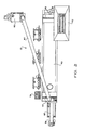
- apparatus 10 includes a cylindrical tube 12 having two ends 14 and 16.
- Tube 12 has at least one support wheel 18 at each end 14, 16.
- Rollers 20 are rotatably mounted to base 22, with the rollers 20 contacting the tube support wheels 18 in a supporting relationship, such that the tube 12 is rotatable with respect to base 22.
- First drive means 24 applies rotating force to the tube 12, and includes appropriate chains, sprockets, a gear reduction unit and a variable speed DC electric motor.
- a stationary wet material input chamber 26 is fixed to base 22 at one end 16 of tube 12.
- a stationary dried material and product vapour discharge chamber 28 is fixed to base 22 at the other end 14 of tube 12.
- the ends 14, 16 of tube 12 extend into their associated chambers 28, 26. High temperature seals (not shown) at the ends 14, 16 prevent leakage of material and vapours.
- Auger 30 has two ends 32 and 34. Auger 30 extends through tube 12 and the stationary chambers 26, 28. Auger 30 has a hollow central shaft 36 and is rotatably mounted within tube 12 and supported for rotation by the chambers 26 and 28 at each end 34, 32.
- Second drive means 38 applies rotating force to auger 30, and includes appropriate chains, sprockets, a gear reduction unit and a variable speed electric motor.
- An insulated cover 40 for tube 12 is sized to provide an annular space 42 within the cover 40 about the tube 12.
- a plurality of gas-fired burners 44 are in communication with the annulus 42 to heat the exterior 44 of the tube 12.
- conduit 46 connects the annulus 42 to the end 34 of the auger hollow shaft 36 at the wet material input chamber 26 by way of a blower 48.
- a blower 48 connects the annulus 42 to the end 34 of the auger hollow shaft 36 at the wet material input chamber 26 by way of a blower 48.
- Feed means 50 is provided to introduce wet material 52 into the wet material input chamber 26 and thereby into the interior annulus 54 of tube 12 and the exterior 56 of auger 30.
- Discharge means 58 is provided to receive dried material 60 at the bottom end 61 of the dried material and product vapor discharge chamber 28.
- First vent means 62 is connected to the top 64 of the dried material and product vapor discharge chamber 28 for exhausting fumes 68 from the tube 12 and chamber 28.
- Second vent means 70 is connected to the end 32 of the auger hollow shaft 36 at the dried material and product vapor discharge chamber 28 for exhausting combustion gases 72.
- a third vent means 74 exhausts the remaining combustion gases 76.
- a control panel 78 provides for burner and DC motor speed control.
- Air treatment apparatus 80 may be optionally provided at the discharge of first vent means 62.
- Conveyor 82 may be optionally provided for handling dried material produced by the apparatus.
- apparatus 10 has as its main component cylindrical tube 12 which has large diameter steel support wheels 18 on both ends. These wheels 18 are positioned on rollers 20 mounted to the base 22 to allow the rotation of the dehydration chamber provided by tube 12.
- the chamber is driven with chains and sprocketing attached to a gear reduction unit and powered by a variable speed DC motor. Both the "wet end” (wet material input chamber 26) and the “dry end” (dried material and product vapor discharge chamber 28) are stationary chambers.
- the dehydration chamber extends into these chambers. High temperature seals located on either end around the chambers prevent leakage of the material and vapors.
- This auger 30 is also driven with chains and sprocketing attached to a gear reduction unit powered by a variable speed DC motor.
- the rotating dryer chamber is housed inside the insulated metal cover 40 with several inches of air spacing left between the insulation and the tube 12. Heat from the gas-fired burners 44 is introduced into this annulus through a plenum located in the lower section of annulus 42 before being exhausted to the atmosphere. This method allows the slow rotating chamber to be heated uniformly around the entire diameter. When required, a portion of the hot combustion gases may be drawn from the annulus 42 by a blower 48 and injected into the "wet end" of the hollow auger shaft 36. These are also exhausted to the atmosphere at the "dry end” of the system.
- the material 52 to be dehydrated can be metered into the chamber 26 by either a variable speed screw auger or metering pump.
- the wet material is subjected to the indirect heat of the chamber walls and, if desired, the heated hollow auger shaft.
- the dried material 60 is discharged out of the dryer tube through the bottom of the "dry end" stationary chamber. The vapors coming off of the product are exhausted out the top of this end.
- the type and make-up of the material and the air quality regulatory agency requirements that must be met in specific areas will determine what type of air-handling equipment 80, if any, will be required.
Landscapes
- Engineering & Computer Science (AREA)
- Mechanical Engineering (AREA)
- General Engineering & Computer Science (AREA)
- Drying Of Solid Materials (AREA)
- Washing And Drying Of Tableware (AREA)
- Centrifugal Separators (AREA)
- Physical Vapour Deposition (AREA)
Claims (11)
- Vorrichtung für thermische Verdampfung, umfassend: eine zylindrische Röhre (12) mit einem Auslassende (14) und einem Einlassende (16); eine Basis (22), wobei die Röhre (12) mit Bezug auf die Basis (22) rotierbar ist; eine erste Antriebseinrichtung (24) zum Ausüben von Drehkraft auf die Röhre; eine Schnecke (30), die zwei Enden hat und sich durch die Röhre hindurch erstreckt; eine zweite Antriebseinrichtung (38) zum Ausüben von Drehkraft auf die Schnecke (30); wenigstens eine Heizeinrichtung (44) zum Heizen des Äußeren der Röhre (12) während der Rotation, Zuführeinrichtung (50) zum Einführen von nassem Material in das Innere der Röhre (12) außerhalb der Schnecke in der Röhre an einem Ende (16) der Röhre; gekennzeichnet durch eine an der Basis (22) befestigte unbewegliche Nassmaterialeingangskammer (26) an einem Ende (16) der Röhre und eine an der Basis befestigte unbewegliche Trockenmaterial- und Produktdampfaustragskammer (28) und dadurch, dass das Einlassende (16) der Röhre sich in die Eingangskammer (26) und das Auslassende (14) der Röhre sich in die unbewegliche Trockenmaterial- und Produktdampfaustragskammer (28) hinein erstreckt.
- Vorrichtung nach Anspruch 1, die an den Enden (14, 16) der Röhre Hochtemperaturdichtungen zum Verhindern von Material- und Dampflecks hat.
- Vorrichtung nach Anspruch 1 oder Anspruch 2, dadurch gekennzeichnet, dass die Schnecke (30) sich durch die Röhre (12) und die unbeweglichen Kammern (26, 28) hindurch erstreckt.
- Vorrichtung nach Anspruch 3, dadurch gekennzeichnet, dass die Schnecke (30) an jedem Ende von den Kammern (26, 28) drehbar getragen wird.
- Vorrichtung nach einem der vorhergehenden Ansprüche, gekennzeichnet durch eine wärmegedämmte Abdeckung (40) für die Röhre (12), die bemessen ist, um in der Abdeckung um die Röhre herum einen ringförmigen Raum (42) bereitzustellen, wobei die Heizeinrichtung (44) mit dem ringförmigen Raum (42) in Kommunikation steht.
- Vorrichtung nach Anspruch 5, dadurch gekennzeichnet, dass die Schnecke (30) eine zentrale Hohlwelle (36) und eine Leitung (46), die den ringförmigen Raum (42) mit einem Ende der Schneckenhohlwelle (36) verbindet, hat.
- Vorrichtung nach Anspruch 6, dadurch gekennzeichnet, dass die Leitung (46) den ringförmigen Raum mit dem Eingangsende (34) der Schneckenwelle (36) verbindet, und dadurch, dass Schneckenentlüftungsmittel (70) mit dem Ende (32) der Schneckenhohlwelle an der Trockenmaterial- und Produktdampfaustragskammer (28) verbunden ist zum Aussaugen von Verbrennungsdämpfen aus wenigstens einem Brenner, der die Heizeinrichtung (44) bildet.
- Vorrichtung nach Anspruch 7, dadurch gekennzeichnet, dass die Leitung (46) ein Gebläse (48) aufweist.
- Vorrichtung nach einem der vorhergehenden Ansprüche, dadurch gekennzeichnet, dass die Röhrenentlüftungsmittel (62) mit dem oberen Ende der Trockenmaterial- und Produktdampfaustragskammer (28) verbunden sind zum Absaugen von Dämpfen aus der Röhre (12) und der Kammer (28).
- Vorrichtung nach einem der vorhergehenden Ansprüche, die eine Zuführeinrichtung (50) zum Einführen von nassem Material (52) in die Nassmaterialeingangskammer (26) der Röhre hat.
- Vorrichtung nach einem der vorhergehenden Ansprüche, die eine Austragseinrichtung zum Aufnehmen von Trockenmaterial (60) an einem unteren Ende der Trockenmaterial- und Produktdampfaustragskammer (28) hat.
Applications Claiming Priority (3)
| Application Number | Priority Date | Filing Date | Title |
|---|---|---|---|
| US08/503,475 US5566469A (en) | 1995-07-18 | 1995-07-18 | Drying apparatus with rotatable housing |
| CA002198078A CA2198078C (en) | 1995-07-18 | 1996-10-21 | Drying apparatus with rotatable housing |
| PCT/US1996/016768 WO1998017957A1 (en) | 1995-07-18 | 1996-10-21 | Drying apparatus with rotatable housing |
Publications (2)
| Publication Number | Publication Date |
|---|---|
| EP0868639A1 EP0868639A1 (de) | 1998-10-07 |
| EP0868639B1 true EP0868639B1 (de) | 2003-04-23 |
Family
ID=27170282
Family Applications (1)
| Application Number | Title | Priority Date | Filing Date |
|---|---|---|---|
| EP96938632A Expired - Lifetime EP0868639B1 (de) | 1995-07-18 | 1996-10-21 | Trocknungsvorrichtung mit drehbarem gehäuse |
Country Status (11)
| Country | Link |
|---|---|
| US (1) | US5566469A (de) |
| EP (1) | EP0868639B1 (de) |
| AT (1) | ATE238530T1 (de) |
| AU (1) | AU699980B2 (de) |
| BR (1) | BR9610749A (de) |
| CA (1) | CA2198078C (de) |
| DE (1) | DE69627701T2 (de) |
| ES (1) | ES2197254T3 (de) |
| IL (1) | IL120780A (de) |
| MX (1) | MXPA98000544A (de) |
| WO (1) | WO1998017957A1 (de) |
Families Citing this family (16)
| Publication number | Priority date | Publication date | Assignee | Title |
|---|---|---|---|---|
| US5566469A (en) * | 1995-07-18 | 1996-10-22 | Fen-Tech Environmental, Inc. | Drying apparatus with rotatable housing |
| US5927970A (en) * | 1996-10-02 | 1999-07-27 | Onsite Technology, L.L.C. | Apparatus for recovering hydrocarbons from solids |
| US6061924A (en) * | 1997-03-28 | 2000-05-16 | Rubicon Development Co. L.L.C. | Batch sludge dehydrator |
| US5908291A (en) * | 1998-05-01 | 1999-06-01 | Harper International Corp. | Continuous cross-flow rotary kiln |
| NZ517989A (en) | 1999-10-05 | 2003-01-31 | Rubicon Dev Company L | Batch sludge dehydrator |
| US6412428B1 (en) * | 2000-12-20 | 2002-07-02 | Vincent Promuto | Method and apparatus for drying and incineration of sewage sludge |
| US8081955B2 (en) * | 2005-10-20 | 2011-12-20 | Research In Motion Limited | Managing content to constrained devices |
| RU2393398C1 (ru) * | 2009-06-02 | 2010-06-27 | Юрий Сергеевич Волобуев | Установка для термической сушки дисперсного сыпучего материала |
| CN101793460B (zh) * | 2010-02-26 | 2011-12-21 | 杨正清 | 炉渣烘干机 |
| US20150027039A1 (en) * | 2013-07-26 | 2015-01-29 | Scott Laskowski | Apparatus and method for drying biomass |
| CN103512332B (zh) * | 2013-09-23 | 2015-12-23 | 李小波 | 用于干燥粮食的小型烘干机 |
| JP5778831B1 (ja) * | 2014-03-31 | 2015-09-16 | 月島機械株式会社 | 被処理物の乾燥方法、および横型回転式乾燥機 |
| JP5847350B1 (ja) * | 2015-09-15 | 2016-01-20 | 月島機械株式会社 | テレフタル酸の乾燥方法および横型回転式乾燥機 |
| CN106225442B (zh) * | 2016-08-03 | 2018-07-20 | 杨松 | 一种制备活性白土二次活化烘干回转炉 |
| CN111023745A (zh) * | 2019-12-25 | 2020-04-17 | 巢湖美维食品有限公司 | 一种蔬菜果干零食加工用脱水装置 |
| CN114739129B (zh) * | 2022-04-08 | 2023-09-26 | 郑州沃特节能科技股份有限公司 | 一种基于余热回收再利用的烘干系统 |
Family Cites Families (17)
| Publication number | Priority date | Publication date | Assignee | Title |
|---|---|---|---|---|
| DE67942C (de) * | F. DIPPE in Schladen | Trockenvorrichtung für Rübenschnitzel u. dergl | ||
| US1318133A (en) * | 1919-10-07 | Drier | ||
| FR804131A (fr) * | 1935-03-28 | 1936-10-16 | Perfectionnements aux fours rotatifs, séchoirs et appareils similaires | |
| US2069164A (en) * | 1935-06-26 | 1937-01-26 | Smidth & Co As F L | Rotary kiln |
| US2311824A (en) * | 1941-04-30 | 1943-02-23 | Arthur G Gautreau | Drying apparatus |
| US3494049A (en) * | 1968-03-18 | 1970-02-10 | Universal Oil Prod Co | Apparatus for fluid treatment of granular material |
| DE2060027C3 (de) * | 1970-12-05 | 1974-06-06 | Wibau (Westdeutsche Industrie- Und Strassenbau-Maschinen-Gesellschaft Mbh), 6461 Rothenbergen | Indirekt beheizter Trommeltrockner |
| US3805406A (en) * | 1971-09-03 | 1974-04-23 | A Castonoli | Interchangeable path drying apparatus |
| GB1585584A (en) * | 1976-06-08 | 1981-03-04 | Kobe Steel Ltd | Process and apparatus for heating solid materials containing volatile matter |
| US4181846A (en) * | 1977-10-05 | 1980-01-01 | Cunningham Ronald J | Rotary heating apparatus |
| JPS6117885A (ja) * | 1984-07-03 | 1986-01-25 | 株式会社 大和三光製作所 | 通気式回転乾燥装置 |
| US4649655A (en) * | 1986-02-13 | 1987-03-17 | Atlantic Richfield Company | Drilling mud dehydration system |
| US4854941A (en) * | 1988-04-12 | 1989-08-08 | Cli International Enterprises, Inc. | Method and apparatus for drying fine coal |
| CA2011123A1 (en) * | 1989-03-17 | 1990-09-17 | Richard M. Henderson | Method of and apparatus for determining stem content of baled tobacco |
| IT1248826B (it) * | 1990-05-29 | 1995-01-30 | Spada Massimiliano | Essicatore continuo |
| JP2960554B2 (ja) * | 1990-12-27 | 1999-10-06 | 株式会社オーケー企画研究所 | 生ごみ処理車 |
| US5566469A (en) * | 1995-07-18 | 1996-10-22 | Fen-Tech Environmental, Inc. | Drying apparatus with rotatable housing |
-
1995
- 1995-07-18 US US08/503,475 patent/US5566469A/en not_active Expired - Lifetime
-
1996
- 1996-10-21 IL IL12078096A patent/IL120780A/en not_active IP Right Cessation
- 1996-10-21 AT AT96938632T patent/ATE238530T1/de not_active IP Right Cessation
- 1996-10-21 BR BR9610749-9A patent/BR9610749A/pt not_active IP Right Cessation
- 1996-10-21 WO PCT/US1996/016768 patent/WO1998017957A1/en not_active Ceased
- 1996-10-21 DE DE69627701T patent/DE69627701T2/de not_active Expired - Lifetime
- 1996-10-21 AU AU75963/96A patent/AU699980B2/en not_active Ceased
- 1996-10-21 ES ES96938632T patent/ES2197254T3/es not_active Expired - Lifetime
- 1996-10-21 CA CA002198078A patent/CA2198078C/en not_active Expired - Fee Related
- 1996-10-21 EP EP96938632A patent/EP0868639B1/de not_active Expired - Lifetime
- 1996-10-21 MX MXPA98000544A patent/MXPA98000544A/es not_active IP Right Cessation
Also Published As
| Publication number | Publication date |
|---|---|
| EP0868639A1 (de) | 1998-10-07 |
| US5566469A (en) | 1996-10-22 |
| MXPA98000544A (es) | 2004-08-23 |
| DE69627701T2 (de) | 2004-03-11 |
| DE69627701D1 (de) | 2003-05-28 |
| CA2198078C (en) | 2000-03-14 |
| AU699980B2 (en) | 1998-12-17 |
| AU7596396A (en) | 1998-05-15 |
| BR9610749A (pt) | 1999-12-21 |
| WO1998017957A1 (en) | 1998-04-30 |
| IL120780A0 (en) | 1997-11-20 |
| ATE238530T1 (de) | 2003-05-15 |
| ES2197254T3 (es) | 2004-01-01 |
| CA2198078A1 (en) | 1998-04-21 |
| IL120780A (en) | 2001-07-24 |
Similar Documents
| Publication | Publication Date | Title |
|---|---|---|
| EP0868639B1 (de) | Trocknungsvorrichtung mit drehbarem gehäuse | |
| US5088856A (en) | Radiant heat rotary volatilizer | |
| DE69719710D1 (de) | Pyrolysevorrichtung | |
| US20050000108A1 (en) | Sludge dryer | |
| US5338188A (en) | Radiant heat rotary volatilizer | |
| CA2237414A1 (fr) | Traitement de residus humides contenant une charge polluante et/ou toxique | |
| US6195909B1 (en) | Infrared dryer with air purge shutter | |
| KR100318687B1 (ko) | 회전가능한하우징을갖춘건조장치 | |
| US4643108A (en) | Apparatus for dehydrating metal hydroxide sludge | |
| US5938433A (en) | Soil remediation system having heat-loss dust decontamination apparatus | |
| JP2000501166A (ja) | 回転自在なハウジングを備えた乾燥装置 | |
| KR20190063206A (ko) | 유기성 고형물 건조장치 | |
| AU766575B2 (en) | Batch sludge dehydrator | |
| WO1992002773A1 (en) | Rotary heat-treatment apparatus | |
| IL42238A (en) | Drying apparatus | |
| JPH1123152A (ja) | 遠心薄膜乾燥機およびこれを用いた汚泥処理方法 | |
| KR100610301B1 (ko) | 연속 탄화 장치 | |
| KR100372897B1 (ko) | 건조장치 | |
| KR20150134712A (ko) | 직접 가열식 드럼형 슬러지 건조장치 | |
| KR20040062824A (ko) | 음식물쓰레기 무취발효소멸 건조장치 | |
| JPH07239184A (ja) | スクリュ式乾燥機 | |
| US3371426A (en) | Dehydrating drum | |
| CN116123851A (zh) | 一种带有多级控温结构的中药材干燥设备 | |
| JP3840584B2 (ja) | 汚泥の炭化処理装置 | |
| KR100809459B1 (ko) | 건조된 유기성 페기물의 탄화처리장치 |
Legal Events
| Date | Code | Title | Description |
|---|---|---|---|
| PUAI | Public reference made under article 153(3) epc to a published international application that has entered the european phase |
Free format text: ORIGINAL CODE: 0009012 |
|
| 17P | Request for examination filed |
Effective date: 19980721 |
|
| AK | Designated contracting states |
Kind code of ref document: A1 Designated state(s): AT BE CH DE DK ES FR GB IT LI NL SE |
|
| 17Q | First examination report despatched |
Effective date: 20000215 |
|
| GRAH | Despatch of communication of intention to grant a patent |
Free format text: ORIGINAL CODE: EPIDOS IGRA |
|
| GRAH | Despatch of communication of intention to grant a patent |
Free format text: ORIGINAL CODE: EPIDOS IGRA |
|
| GRAA | (expected) grant |
Free format text: ORIGINAL CODE: 0009210 |
|
| AK | Designated contracting states |
Designated state(s): AT BE CH DE DK ES FR GB IT LI NL SE |
|
| PG25 | Lapsed in a contracting state [announced via postgrant information from national office to epo] |
Ref country code: NL Free format text: LAPSE BECAUSE OF FAILURE TO SUBMIT A TRANSLATION OF THE DESCRIPTION OR TO PAY THE FEE WITHIN THE PRESCRIBED TIME-LIMIT Effective date: 20030423 Ref country code: LI Free format text: LAPSE BECAUSE OF FAILURE TO SUBMIT A TRANSLATION OF THE DESCRIPTION OR TO PAY THE FEE WITHIN THE PRESCRIBED TIME-LIMIT Effective date: 20030423 Ref country code: CH Free format text: LAPSE BECAUSE OF FAILURE TO SUBMIT A TRANSLATION OF THE DESCRIPTION OR TO PAY THE FEE WITHIN THE PRESCRIBED TIME-LIMIT Effective date: 20030423 Ref country code: BE Free format text: LAPSE BECAUSE OF FAILURE TO SUBMIT A TRANSLATION OF THE DESCRIPTION OR TO PAY THE FEE WITHIN THE PRESCRIBED TIME-LIMIT Effective date: 20030423 Ref country code: AT Free format text: LAPSE BECAUSE OF FAILURE TO SUBMIT A TRANSLATION OF THE DESCRIPTION OR TO PAY THE FEE WITHIN THE PRESCRIBED TIME-LIMIT Effective date: 20030423 |
|
| REG | Reference to a national code |
Ref country code: GB Ref legal event code: FG4D |
|
| REG | Reference to a national code |
Ref country code: CH Ref legal event code: EP |
|
| REF | Corresponds to: |
Ref document number: 69627701 Country of ref document: DE Date of ref document: 20030528 Kind code of ref document: P |
|
| PG25 | Lapsed in a contracting state [announced via postgrant information from national office to epo] |
Ref country code: SE Free format text: LAPSE BECAUSE OF FAILURE TO SUBMIT A TRANSLATION OF THE DESCRIPTION OR TO PAY THE FEE WITHIN THE PRESCRIBED TIME-LIMIT Effective date: 20030723 Ref country code: DK Free format text: LAPSE BECAUSE OF FAILURE TO SUBMIT A TRANSLATION OF THE DESCRIPTION OR TO PAY THE FEE WITHIN THE PRESCRIBED TIME-LIMIT Effective date: 20030723 |
|
| NLV1 | Nl: lapsed or annulled due to failure to fulfill the requirements of art. 29p and 29m of the patents act | ||
| REG | Reference to a national code |
Ref country code: CH Ref legal event code: PL |
|
| REG | Reference to a national code |
Ref country code: ES Ref legal event code: FG2A Ref document number: 2197254 Country of ref document: ES Kind code of ref document: T3 |
|
| ET | Fr: translation filed | ||
| PLBE | No opposition filed within time limit |
Free format text: ORIGINAL CODE: 0009261 |
|
| STAA | Information on the status of an ep patent application or granted ep patent |
Free format text: STATUS: NO OPPOSITION FILED WITHIN TIME LIMIT |
|
| 26N | No opposition filed |
Effective date: 20040126 |
|
| PGFP | Annual fee paid to national office [announced via postgrant information from national office to epo] |
Ref country code: ES Payment date: 20091117 Year of fee payment: 14 Ref country code: DE Payment date: 20091015 Year of fee payment: 14 |
|
| PGFP | Annual fee paid to national office [announced via postgrant information from national office to epo] |
Ref country code: IT Payment date: 20091020 Year of fee payment: 14 Ref country code: GB Payment date: 20091021 Year of fee payment: 14 Ref country code: FR Payment date: 20091029 Year of fee payment: 14 |
|
| GBPC | Gb: european patent ceased through non-payment of renewal fee |
Effective date: 20101021 |
|
| PG25 | Lapsed in a contracting state [announced via postgrant information from national office to epo] |
Ref country code: FR Free format text: LAPSE BECAUSE OF NON-PAYMENT OF DUE FEES Effective date: 20101102 |
|
| REG | Reference to a national code |
Ref country code: FR Ref legal event code: ST Effective date: 20110630 |
|
| PG25 | Lapsed in a contracting state [announced via postgrant information from national office to epo] |
Ref country code: GB Free format text: LAPSE BECAUSE OF NON-PAYMENT OF DUE FEES Effective date: 20101021 |
|
| REG | Reference to a national code |
Ref country code: DE Ref legal event code: R119 Ref document number: 69627701 Country of ref document: DE Effective date: 20110502 |
|
| REG | Reference to a national code |
Ref country code: ES Ref legal event code: FD2A Effective date: 20111118 |
|
| PG25 | Lapsed in a contracting state [announced via postgrant information from national office to epo] |
Ref country code: IT Free format text: LAPSE BECAUSE OF NON-PAYMENT OF DUE FEES Effective date: 20101021 |
|
| PG25 | Lapsed in a contracting state [announced via postgrant information from national office to epo] |
Ref country code: ES Free format text: LAPSE BECAUSE OF NON-PAYMENT OF DUE FEES Effective date: 20101022 |
|
| PG25 | Lapsed in a contracting state [announced via postgrant information from national office to epo] |
Ref country code: DE Free format text: LAPSE BECAUSE OF NON-PAYMENT OF DUE FEES Effective date: 20110502 |