EP0868736B1 - Systeme de declenchement thermique - Google Patents
Systeme de declenchement thermique Download PDFInfo
- Publication number
- EP0868736B1 EP0868736B1 EP96946142A EP96946142A EP0868736B1 EP 0868736 B1 EP0868736 B1 EP 0868736B1 EP 96946142 A EP96946142 A EP 96946142A EP 96946142 A EP96946142 A EP 96946142A EP 0868736 B1 EP0868736 B1 EP 0868736B1
- Authority
- EP
- European Patent Office
- Prior art keywords
- slide
- switching element
- switching
- differential lever
- bearing
- Prior art date
- Legal status (The legal status is an assumption and is not a legal conclusion. Google has not performed a legal analysis and makes no representation as to the accuracy of the status listed.)
- Expired - Lifetime
Links
- 238000004519 manufacturing process Methods 0.000 claims description 4
- 238000000034 method Methods 0.000 description 6
- 230000001419 dependent effect Effects 0.000 description 2
- 230000000694 effects Effects 0.000 description 2
- 238000010438 heat treatment Methods 0.000 description 2
- 238000004080 punching Methods 0.000 description 1
- 230000001960 triggered effect Effects 0.000 description 1
Images
Classifications
-
- H—ELECTRICITY
- H01—ELECTRIC ELEMENTS
- H01H—ELECTRIC SWITCHES; RELAYS; SELECTORS; EMERGENCY PROTECTIVE DEVICES
- H01H83/00—Protective switches, e.g. circuit-breaking switches, or protective relays operated by abnormal electrical conditions otherwise than solely by excess current
- H01H83/20—Protective switches, e.g. circuit-breaking switches, or protective relays operated by abnormal electrical conditions otherwise than solely by excess current operated by excess current as well as by some other abnormal electrical condition
- H01H83/22—Protective switches, e.g. circuit-breaking switches, or protective relays operated by abnormal electrical conditions otherwise than solely by excess current operated by excess current as well as by some other abnormal electrical condition the other condition being imbalance of two or more currents or voltages
- H01H83/223—Protective switches, e.g. circuit-breaking switches, or protective relays operated by abnormal electrical conditions otherwise than solely by excess current operated by excess current as well as by some other abnormal electrical condition the other condition being imbalance of two or more currents or voltages with bimetal elements
-
- Y—GENERAL TAGGING OF NEW TECHNOLOGICAL DEVELOPMENTS; GENERAL TAGGING OF CROSS-SECTIONAL TECHNOLOGIES SPANNING OVER SEVERAL SECTIONS OF THE IPC; TECHNICAL SUBJECTS COVERED BY FORMER USPC CROSS-REFERENCE ART COLLECTIONS [XRACs] AND DIGESTS
- Y10—TECHNICAL SUBJECTS COVERED BY FORMER USPC
- Y10T—TECHNICAL SUBJECTS COVERED BY FORMER US CLASSIFICATION
- Y10T29/00—Metal working
- Y10T29/49—Method of mechanical manufacture
- Y10T29/49002—Electrical device making
- Y10T29/49105—Switch making
-
- Y—GENERAL TAGGING OF NEW TECHNOLOGICAL DEVELOPMENTS; GENERAL TAGGING OF CROSS-SECTIONAL TECHNOLOGIES SPANNING OVER SEVERAL SECTIONS OF THE IPC; TECHNICAL SUBJECTS COVERED BY FORMER USPC CROSS-REFERENCE ART COLLECTIONS [XRACs] AND DIGESTS
- Y10—TECHNICAL SUBJECTS COVERED BY FORMER USPC
- Y10T—TECHNICAL SUBJECTS COVERED BY FORMER US CLASSIFICATION
- Y10T29/00—Metal working
- Y10T29/49—Method of mechanical manufacture
- Y10T29/49002—Electrical device making
- Y10T29/49107—Fuse making
Definitions
- the invention relates to a method for manufacturing of a thermal release system for an electrical switching device with bimetallic elements, a slide with receptacles, in which the bimetallic elements are included with Switching element for triggering a switching process, with a Differential lever that is attached to the slide and by movement the same in the direction of thrust its distance from the switching element shortened, the attachment of the differential lever via a first and a second bearing on the slide.
- Such thermal tripping systems are in circuit breakers realized.
- the switch is not directly, but via the Operated slide, which is adapted to the position of the bimetallic strips is.
- the differential lever is countered by the slide pressed the switching element and thus triggers the switching process out.
- the components of the switching device are inevitable Provide tolerances and in their arrangement and effect with each other they form a chain of tolerance. Their effect must be on fully assembled switch can be compensated. For this For this reason, it was customary so far to position the switching element to be adjustable. The adjustment was made using a Fine-thread screw, through which a pivoted Carrier for the shift lever can be moved forward or backward could. This way the distance between the Switching element and the differential lever to a predetermined Value a can be set.
- a thermal release system for an electrical switchgear of the above type is disclosed in US-A-4,691,184. This contains independent calibration or adjustment elements.
- the invention has for its object the method for Manufacture of a thermal release system of the above Art to improve in that on previously used adjustment elements can be dispensed with, in order to save costs.
- the stated object is achieved in that the slide with the first bearing designed as a fulcrum is made that the position of the switching element in electrical switching device is measured that depends on the measured position of the switching element in the second bearing calculates and is executed on the slide, which is then in associated switchgear is installed.
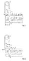
- the thermal release system 1 generally comprises three bimetal strips 2, each with a not shown here Heating coil are provided, a slide 3, a differential lever 4 and a switching element 5.
- the slider 3 there are receiving slots 6 incorporated, in which the bimetal strips 2 stuck.
- the slider 3 is a due to the deflection or several bimetal strips 2 when overload currents occur in the direction of thrust indicated by a double arrow 7 slidable.
- On the slide 3 is essentially Differential lever 4 aligned transversely to the direction of thrust attached, at its end facing the switching element 5 has a nose 8. This nose 8 has a temperature the bimetal strip 2, i.e.
- the differential lever 4 is over two Bearing points 9,10 attached to the slide 3.
- the first depository 9 is a fixed point with respect to the slide 3, a distance y to the switching element 5 in the de-energized state in the direction of thrust. This distance y depends on the Manufacturing tolerances differ from device to device, i.e. a device-specific size.
- the two bearings 9,10 are preferably on one in essentially straight lines oriented transversely to the direction of thrust located.
- the slider 3 with only one Made bearing 9, which serves as a fulcrum.
- the location of the switching element 5 in the trigger system 1 is measured what is triggered very precisely by triggering the switching process.
- the position for the second bearing 10 is dependent on this calculated and this e.g. made by punching.
- the slide 3 is mounted in the associated switching device.
- the second bearing point is a slot 10 executed.
Landscapes
- Thermally Actuated Switches (AREA)
- Manufacture Of Switches (AREA)
- Breakers (AREA)
Claims (1)
- Procédé de fabrication d'un système de déclenchement thermique d'un appareil de commutation électrique, comportant des bilames (2), un coulisseau (3) avec des logements (6) dans lesquels sont reçus les bilames (2), un élément (5) de commutation pour déclencher une opération de commutation, et un levier (4) différentiel, qui est fixé sur le coulisseau (3) et, par le déplacement de ce dernier dans la direction de poussée, réduit sa distance (x) de l'élément (5) de commutation, la fixation du levier différentiel s'effectuant au moyen d'un premier (9) et d'un deuxième (10) point d'appui sur le coulisseau (3),
caractérisé en ce qu'on fabrique le coulisseau (3) avec le premier (9) point d'appui conçu comme centre de rotation, en ce qu'on mesure la position de l'élément (5) de commutation dans l'appareil de commutation électrique, en ce qu'on calcule le deuxième (10) point d'appui en fonction de la position mesurée de l'élément (5) de commutation et on le réalise sur le coulisseau (3), qui est ensuite montée dans l'appareil de commutation correspondant.
Applications Claiming Priority (3)
| Application Number | Priority Date | Filing Date | Title |
|---|---|---|---|
| DE19548479 | 1995-12-22 | ||
| DE19548479A DE19548479C2 (de) | 1995-12-22 | 1995-12-22 | Thermisches Auslösesystem |
| PCT/DE1996/002356 WO1997023887A2 (fr) | 1995-12-22 | 1996-12-09 | Systeme de declenchement thermique |
Publications (2)
| Publication Number | Publication Date |
|---|---|
| EP0868736A2 EP0868736A2 (fr) | 1998-10-07 |
| EP0868736B1 true EP0868736B1 (fr) | 1999-08-25 |
Family
ID=7781241
Family Applications (1)
| Application Number | Title | Priority Date | Filing Date |
|---|---|---|---|
| EP96946142A Expired - Lifetime EP0868736B1 (fr) | 1995-12-22 | 1996-12-09 | Systeme de declenchement thermique |
Country Status (5)
| Country | Link |
|---|---|
| US (1) | US6014803A (fr) |
| EP (1) | EP0868736B1 (fr) |
| JP (1) | JP2000506665A (fr) |
| DE (2) | DE19548479C2 (fr) |
| WO (1) | WO1997023887A2 (fr) |
Families Citing this family (2)
| Publication number | Priority date | Publication date | Assignee | Title |
|---|---|---|---|---|
| DE10104901A1 (de) * | 2001-02-03 | 2002-08-08 | Abb Patent Gmbh | Verfahren zum Justieren des thermischen Auslösesystems eines elektrischen Schaltgerätes, insbesondere eines Motorschutzschalters |
| DE102008062527B4 (de) * | 2008-12-16 | 2022-08-11 | Abb Schweiz Ag | Mehrphasiges elektrisches Schaltgerät mit einem Auslöseschieber sowie ein Auslöseschieber |
Family Cites Families (6)
| Publication number | Priority date | Publication date | Assignee | Title |
|---|---|---|---|---|
| DE3149811A1 (de) * | 1981-12-16 | 1983-07-21 | Klöckner-Moeller Elektrizitäts GmbH, 5300 Bonn | Mehrphasiger thermisch verzoegerter motorschutzschalter |
| DE3401901A1 (de) * | 1984-01-20 | 1985-08-01 | Brown, Boveri & Cie Ag, 6800 Mannheim | Thermisches ueberstromrelais mit justierexzenter |
| DE3415226A1 (de) * | 1984-04-21 | 1985-10-31 | Brown, Boveri & Cie Ag, 6800 Mannheim | Thermisches ueberstromrelais mit justierbuegel |
| DE3435228A1 (de) * | 1984-09-26 | 1986-04-03 | Licentia Patent-Verwaltungs-Gmbh, 6000 Frankfurt | Bimetallausloeser |
| US4806897A (en) * | 1987-12-17 | 1989-02-21 | Eaton Corporation | Overload relay having adaptive differential mechanism |
| FR2667979B1 (fr) * | 1990-10-11 | 1994-04-01 | Telemecanique | Declencheur thermique differentiel a bilames. |
-
1995
- 1995-12-22 DE DE19548479A patent/DE19548479C2/de not_active Expired - Fee Related
-
1996
- 1996-12-09 WO PCT/DE1996/002356 patent/WO1997023887A2/fr not_active Ceased
- 1996-12-09 JP JP09523202A patent/JP2000506665A/ja active Pending
- 1996-12-09 US US09/091,445 patent/US6014803A/en not_active Expired - Lifetime
- 1996-12-09 EP EP96946142A patent/EP0868736B1/fr not_active Expired - Lifetime
- 1996-12-09 DE DE59602913T patent/DE59602913D1/de not_active Expired - Lifetime
Also Published As
| Publication number | Publication date |
|---|---|
| DE19548479C2 (de) | 1999-09-02 |
| DE59602913D1 (de) | 1999-09-30 |
| JP2000506665A (ja) | 2000-05-30 |
| EP0868736A2 (fr) | 1998-10-07 |
| US6014803A (en) | 2000-01-18 |
| WO1997023887A2 (fr) | 1997-07-03 |
| WO1997023887A3 (fr) | 1997-09-12 |
| DE19548479A1 (de) | 1997-06-26 |
Similar Documents
| Publication | Publication Date | Title |
|---|---|---|
| DE69403022T2 (de) | Einstellvorrichtung des Auslöseansprechwerts eines mehrpoligen Schutzschalters | |
| DE3531710C2 (de) | Durch Zusammenbau von Modulelementen realisierbare Schaltvorrichtung mit veränderlicher Zusammensetzung | |
| DE68912088T2 (de) | Magnetischer Auslöser mit breitem Bereich zur Regelung des Auslöseansprechwertes. | |
| DE69403023T2 (de) | Hilfsauslöser für Schutzschalter | |
| DE69230817T2 (de) | Schaltermechanismus | |
| DE69026025T2 (de) | Schalter mit einstellbarem magnetischem Niederstromauslöser | |
| DE3739806C2 (fr) | ||
| DE4406670A1 (de) | Leitungsschutzschalter | |
| EP0195816B1 (fr) | Declencheur bimetallique | |
| WO2007057030A1 (fr) | Appareil de commutation electrique a magnetostriction | |
| EP0868736B1 (fr) | Systeme de declenchement thermique | |
| DE69517242T2 (de) | Schutzschalter mit zwei unterbrechungsstellen | |
| DE68914970T2 (de) | Unverletzliche Regelungsvorrichtung eines elektrischen Gerätes. | |
| EP0833357B1 (fr) | Procédé pour l'ajustage d'un déclencheur thermique de surcharge | |
| DE1126975B (de) | UEberstromschutzschalter mit thermischer Ausloesung | |
| DE2651158A1 (de) | Abschalter, insbesondere mehrpoliger abschalter | |
| DE7701021U1 (de) | Mehrphasen-Überlastrelais | |
| DE19516723C2 (de) | Thermo-magnetische Auslöseeinrichtung | |
| EP0500138A1 (fr) | Disjoncteur de protection | |
| EP0243648A1 (fr) | Disjoncteur électrique | |
| EP0159598B1 (fr) | Relais thermique à courant excessif avec étrier d'ajustement | |
| DE102007010943B4 (de) | Thermischer Überlastauslöser für ein mehrpoliges elektrisches Schaltgerät | |
| DE3877262T4 (de) | Testeinheit für elektrischen Differentialschutzapparat und Apparate mit dieser Einheit. | |
| EP1229565B1 (fr) | Procédé pour ajuster un déclencheur thermique d'un appareil de commutation électrique, en particulier un contacteur | |
| DE69111684T2 (de) | Isolierendes Gehäuse für Miniatur-Lastschalter mit Vorassemblagemitteln. |
Legal Events
| Date | Code | Title | Description |
|---|---|---|---|
| PUAI | Public reference made under article 153(3) epc to a published international application that has entered the european phase |
Free format text: ORIGINAL CODE: 0009012 |
|
| 17P | Request for examination filed |
Effective date: 19980618 |
|
| AK | Designated contracting states |
Kind code of ref document: A2 Designated state(s): CH DE FR LI |
|
| GRAG | Despatch of communication of intention to grant |
Free format text: ORIGINAL CODE: EPIDOS AGRA |
|
| GRAG | Despatch of communication of intention to grant |
Free format text: ORIGINAL CODE: EPIDOS AGRA |
|
| GRAH | Despatch of communication of intention to grant a patent |
Free format text: ORIGINAL CODE: EPIDOS IGRA |
|
| 17Q | First examination report despatched |
Effective date: 19990212 |
|
| GRAH | Despatch of communication of intention to grant a patent |
Free format text: ORIGINAL CODE: EPIDOS IGRA |
|
| GRAA | (expected) grant |
Free format text: ORIGINAL CODE: 0009210 |
|
| AK | Designated contracting states |
Kind code of ref document: B1 Designated state(s): CH DE FR LI |
|
| REG | Reference to a national code |
Ref country code: CH Ref legal event code: NV Representative=s name: SIEMENS SCHWEIZ AG Ref country code: CH Ref legal event code: EP |
|
| REF | Corresponds to: |
Ref document number: 59602913 Country of ref document: DE Date of ref document: 19990930 |
|
| ET | Fr: translation filed | ||
| PLBE | No opposition filed within time limit |
Free format text: ORIGINAL CODE: 0009261 |
|
| STAA | Information on the status of an ep patent application or granted ep patent |
Free format text: STATUS: NO OPPOSITION FILED WITHIN TIME LIMIT |
|
| 26N | No opposition filed | ||
| PGFP | Annual fee paid to national office [announced via postgrant information from national office to epo] |
Ref country code: CH Payment date: 20060308 Year of fee payment: 10 |
|
| PG25 | Lapsed in a contracting state [announced via postgrant information from national office to epo] |
Ref country code: LI Free format text: LAPSE BECAUSE OF NON-PAYMENT OF DUE FEES Effective date: 20061231 Ref country code: CH Free format text: LAPSE BECAUSE OF NON-PAYMENT OF DUE FEES Effective date: 20061231 |
|
| REG | Reference to a national code |
Ref country code: CH Ref legal event code: PL |
|
| PGFP | Annual fee paid to national office [announced via postgrant information from national office to epo] |
Ref country code: DE Payment date: 20130218 Year of fee payment: 17 Ref country code: FR Payment date: 20130131 Year of fee payment: 17 |
|
| REG | Reference to a national code |
Ref country code: DE Ref legal event code: R119 Ref document number: 59602913 Country of ref document: DE |
|
| REG | Reference to a national code |
Ref country code: DE Ref legal event code: R119 Ref document number: 59602913 Country of ref document: DE Effective date: 20140701 |
|
| REG | Reference to a national code |
Ref country code: FR Ref legal event code: ST Effective date: 20140829 |
|
| PG25 | Lapsed in a contracting state [announced via postgrant information from national office to epo] |
Ref country code: DE Free format text: LAPSE BECAUSE OF NON-PAYMENT OF DUE FEES Effective date: 20140701 |
|
| PG25 | Lapsed in a contracting state [announced via postgrant information from national office to epo] |
Ref country code: FR Free format text: LAPSE BECAUSE OF NON-PAYMENT OF DUE FEES Effective date: 20131231 |