EP0868932A2 - Procédé de separation de composants dans un specimen liquide et l'apparail - Google Patents
Procédé de separation de composants dans un specimen liquide et l'apparail Download PDFInfo
- Publication number
- EP0868932A2 EP0868932A2 EP98105644A EP98105644A EP0868932A2 EP 0868932 A2 EP0868932 A2 EP 0868932A2 EP 98105644 A EP98105644 A EP 98105644A EP 98105644 A EP98105644 A EP 98105644A EP 0868932 A2 EP0868932 A2 EP 0868932A2
- Authority
- EP
- European Patent Office
- Prior art keywords
- separation device
- adsorbent
- specimen
- eluant
- liquid specimen
- Prior art date
- Legal status (The legal status is an assumption and is not a legal conclusion. Google has not performed a legal analysis and makes no representation as to the accuracy of the status listed.)
- Withdrawn
Links
Images


Classifications
-
- G—PHYSICS
- G01—MEASURING; TESTING
- G01N—INVESTIGATING OR ANALYSING MATERIALS BY DETERMINING THEIR CHEMICAL OR PHYSICAL PROPERTIES
- G01N30/00—Investigating or analysing materials by separation into components using adsorption, absorption or similar phenomena or using ion-exchange, e.g. chromatography or field flow fractionation
- G01N30/02—Column chromatography
- G01N30/26—Conditioning of the fluid carrier; Flow patterns
- G01N30/38—Flow patterns
- G01N30/40—Flow patterns using back flushing
-
- B—PERFORMING OPERATIONS; TRANSPORTING
- B01—PHYSICAL OR CHEMICAL PROCESSES OR APPARATUS IN GENERAL
- B01D—SEPARATION
- B01D15/00—Separating processes involving the treatment of liquids with solid sorbents; Apparatus therefor
- B01D15/08—Selective adsorption, e.g. chromatography
- B01D15/10—Selective adsorption, e.g. chromatography characterised by constructional or operational features
- B01D15/18—Selective adsorption, e.g. chromatography characterised by constructional or operational features relating to flow patterns
- B01D15/1807—Selective adsorption, e.g. chromatography characterised by constructional or operational features relating to flow patterns using counter-currents, e.g. fluidised beds
-
- B—PERFORMING OPERATIONS; TRANSPORTING
- B01—PHYSICAL OR CHEMICAL PROCESSES OR APPARATUS IN GENERAL
- B01D—SEPARATION
- B01D15/00—Separating processes involving the treatment of liquids with solid sorbents; Apparatus therefor
- B01D15/08—Selective adsorption, e.g. chromatography
- B01D15/10—Selective adsorption, e.g. chromatography characterised by constructional or operational features
- B01D15/14—Selective adsorption, e.g. chromatography characterised by constructional or operational features relating to the introduction of the feed to the apparatus
-
- G—PHYSICS
- G01—MEASURING; TESTING
- G01N—INVESTIGATING OR ANALYSING MATERIALS BY DETERMINING THEIR CHEMICAL OR PHYSICAL PROPERTIES
- G01N30/00—Investigating or analysing materials by separation into components using adsorption, absorption or similar phenomena or using ion-exchange, e.g. chromatography or field flow fractionation
- G01N30/02—Column chromatography
- G01N30/26—Conditioning of the fluid carrier; Flow patterns
- G01N30/38—Flow patterns
- G01N30/40—Flow patterns using back flushing
- G01N2030/402—Flow patterns using back flushing purging a device
-
- G—PHYSICS
- G01—MEASURING; TESTING
- G01N—INVESTIGATING OR ANALYSING MATERIALS BY DETERMINING THEIR CHEMICAL OR PHYSICAL PROPERTIES
- G01N30/00—Investigating or analysing materials by separation into components using adsorption, absorption or similar phenomena or using ion-exchange, e.g. chromatography or field flow fractionation
- G01N30/02—Column chromatography
- G01N30/26—Conditioning of the fluid carrier; Flow patterns
- G01N30/38—Flow patterns
- G01N30/40—Flow patterns using back flushing
- G01N2030/407—Flow patterns using back flushing carrying out another separation
-
- G—PHYSICS
- G01—MEASURING; TESTING
- G01N—INVESTIGATING OR ANALYSING MATERIALS BY DETERMINING THEIR CHEMICAL OR PHYSICAL PROPERTIES
- G01N30/00—Investigating or analysing materials by separation into components using adsorption, absorption or similar phenomena or using ion-exchange, e.g. chromatography or field flow fractionation
- G01N30/02—Column chromatography
- G01N30/04—Preparation or injection of sample to be analysed
- G01N30/16—Injection
-
- G—PHYSICS
- G01—MEASURING; TESTING
- G01N—INVESTIGATING OR ANALYSING MATERIALS BY DETERMINING THEIR CHEMICAL OR PHYSICAL PROPERTIES
- G01N30/00—Investigating or analysing materials by separation into components using adsorption, absorption or similar phenomena or using ion-exchange, e.g. chromatography or field flow fractionation
- G01N30/02—Column chromatography
- G01N30/04—Preparation or injection of sample to be analysed
- G01N30/24—Automatic injection systems
-
- G—PHYSICS
- G01—MEASURING; TESTING
- G01N—INVESTIGATING OR ANALYSING MATERIALS BY DETERMINING THEIR CHEMICAL OR PHYSICAL PROPERTIES
- G01N30/00—Investigating or analysing materials by separation into components using adsorption, absorption or similar phenomena or using ion-exchange, e.g. chromatography or field flow fractionation
- G01N30/02—Column chromatography
- G01N30/88—Integrated analysis systems specially adapted therefor, not covered by a single one of the groups G01N30/04 - G01N30/86
Definitions
- the present invention relates to a method for separating two or more components in a liquid specimen by utilizing difference of adsorption to an adsorbent, and also to an apparatus used in said method.
- the specimen is applied on a column carrier either directly or by means of a specimen injector.
- the specimen is usually introduced at a site upstream with respect to eluting direction of the specimen.
- the method of the present invention for separating two or more components in a liquid specimen by utilizing difference of adsorption to an adsorbent is characterized in that said liquid specimen is introduced into a separation device from a direction opposite to eluting direction of the separation device which retains the adsorbent, and either one of the substance to be measured or impurities dissolved in the liquid specimen, which adversely affect the measurement, is mostly adsorbed on the adsorbent under a condition where the other of the substance or the impurities is eluted, then the adsorbed substances are separated and eluted from the eluting outlet of the device together with the eluant.
- the separating apparatus comprises a separation device retaining an adsorbent, a liquid specimen injector arranged separately or integrally at a position closer to the outlet of said separation device, and means for reducing pressure or for reducing and increasing pressure in the separation device connected to the inlet side of said separation device.
- the liquid specimen is introduced into the separation device from a direction opposite to the eluting direction.
- trace quantity of insoluble substances is attached to the outlet site of the adsorbent retained in the present device.
- the insoluble substances are removed in the initial stage of elution and do not remain in the separation device.
- This makes it possible to prevent the increase of inner pressure in the separation device caused by clogging of the adsorbent or to avoid ineffective separating operation even when the separating operation is performed repeatedly.
- a liquid specimen is introduced into a separation device from a direction opposite to eluting direction. Accordingly, most of insoluble substances in the liquid specimen are eluted and removed together with the eluant in the initial stage in accordance with the principle of backwash when the eluant is discharged. Also, components adsorbed on the adsorbent are separated by the difference of adsorbing ability.
- an adsorbent which is extremely different in adsorbing ability from a substance A to be measured and impurities B, which adversely affect the measurement.
- the following types of adsorbent should be selected: an adsorbent, which adsorbs and elutes the substance A in a quantity more than the measurable quantity under a certain condition but adsorbs and elutes the impurities B only in such a quantity not adversely affecting the measurement, or an adsorbent, which behaves in the same manner as above with respect to the substance A but does not elute the impurities B only in such a quantity not adversely affecting the measurement even when it adsorbs the impurities B in a quantity more than the quantity adversely affecting the measurement, or an adsorbent, which does not adsorb the substance
- an adsorbent which can almost perfectly adsorb one of either the substance to be measured or the impurities under the condition where the other of the above two substances is eluted.
- the adsorbent includes the one having properties mentioned below, and when such an adsorbent is used, components adsorbed almost perfectly may be eluted according to the type of adsorption as described below.
- the adsorbent may adsorb either the substance to be measured or the impurities, but it is preferable to adsorb the substance to be measured because the impurities usually contain many types of components.
- the substance adsorbed may be eluted by changing ionicity of eluant (i.e. by increasing salt concentration) or by changing pH value.
- This relates to separation of the substances, which are hydrophobically different from each other.
- the substance adsorbed is eluted by decreasing hydrophobic property of the eluant (i.e. by decreasing salt concentration or adding an organic solvent such as methanol, ethanol and acetonitrile).
- an adsorbent which can adsorb substances by ion exchange, hydrophobic adsorption or specific affinity as described above, e.g. ion exchange resin, hydrophobic carrier, hydroxyappatite, a protein A fixed affinity carrier, etc.
- the thickness of the adsorbent may not be specifically limited and no thick adsorbent may be required, and any conventional film or filter paper having ion exchange ability may be used.
- the liquid specimen is serum, urine, etc.
- a reagent taking a role of solvent
- an antibody to the substance to be measured by adding to the system an antibody to the substance to be measured, an immune complex of "the substance to be measured + the antibody” can be formed, whereby more easy separation by hydrophobic adsorption can be attained because of changing the hydrophobic property of said substance.
- an ionic radical into the antibody, an immune complex of "the substance to be measured + the antibody + the ionic radical" can be formed, whereby more easy separation by ion exchange can be attained.
- a labeling substance is bonded to an antibody other than the antibody bonded with the ionic radical and then both this labeled antibody and the above ionic radical bonded antibody are combined with the substance to be measured, whereby the ionic radical and the labeling substance can be introduced into the substance to be measured, and use of the thus obtained substance makes it possible to increase specificity to detect the substance to be measured, particularly when a substance not found in a biological component such as human body component is used as the labeling substance.
- the substance to be measured in the biological components can be effectively separated from free labeled antibody or substances, which may hinder detection and may be contained in the biological component, and this contributes to the improvement of measurement accuracy.
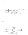
- Fig. 1 is a schematical drawing of an embodiment of a separating apparatus used in the separating method of the present invention.
- a specimen introducing pipe is connected, and the other end off the separation device is connected via a pipe to a pump to reduce or increase pressure in the separation device.
- any type of device may be used so far as it comprises a specimen inlet (elution inlet) and an opening for reducing pressure (for sucking) in the separation device so that the specimen can be introduced therein and that it can retain an adsorbent therein, and its material and shape are not specifically limited.
- a column in cylindrical shape packed with an adsorbent as normally used in column chromatography may generally be used.
- an adsorbent prepared in shape of sheet such as filter paper or in shape of membrane is retained in an expanded part (e.g. in disk-like shape) on the tubular portion of the separation device.
- the specimen inlet is positioned at one end of the separation device, and pressure reducing means is connected to the other end or may be formed on an opening in contact with the atmospheric air.
- a centrifugal filtration tube packed with an adsorbent in shape of membrane may also be used.
- the separation device is used at vertical position directing the eluting outlet as the lower end. In a case where one of either the substance to be measured or the impurities is adsorbed almost completely, it does not matter whether the eluting outlet is at the upper position in vertical use or on lateral side in horizontal use.
- liquid or gas such as air, pure water or eluant is sucked in a quantity higher than the total space volume of the specimen introducing passage so that the liquid specimen attached on the suction passage is flown into the separation device.
- gas or liquid in a quantity higher than the total space volume of the specimen introducing passage from the specimen inlet to the adsorbent in the separation device, almost all of the specimen can be introduced into the adsorbent in the separation device, whereby improvement of measurement sensitivity can be attained.
- eluant when the specimen is adsorbed on the adsorbent, eluant is passed from a site upstream of the separation device toward the eluting outlet, i.e. in eluting direction.
- an eluant normally used in column chromatography may be used according to the type of the adsorbent.
- the eluant may be introduced from a site upstream of the separation device (column), i.e. to a pipe between the pump and the separation device in case of the apparatus shorn in Fig. 1 or it may be introduced from the specimen introducing pipe.
- the introduction of the eluant from the specimen introducing pipe can give such merits that the specimen attached on the suction passage can be introduced and the apparatus can be designed in simplified manner.
- the pump used in the present invention may be any type of pump so far as it can suck the air into or discharge the air from the separation device, and there is no special limitation.
- adsorbent in a case where the pump is used, it is preferable to select such an adsorbent as not giving more than 30 kgf/cm 2 load to the pump under the selected condition. By selecting this type of adsorbent, it is possible to introduce smoothly the specimen from the specimen introducing pipe and also to perform smoothly separation and elution under increasing pressure in the separation device.
- the means for reducing or increasing pressure may not necessarily be a pump.
- a rod-like member may be closely and slidably fitted in an outer tube like a syringe so that liquid specimen can be sucked or discharged.
- the separation device itself may be used as the outer tube or another pipe different from the separation device may be newly equipped.
- a cap may be provided, which is expanded to suck and is deflated to discharge just like a pipette.
- means for increasing pressure is not necessarily required.
- the means for reducing or increasing pressure as described above may be removed under sucked condition, and the eluant sucked may be discharged under atmospheric pressure.
- the separation of the impurities B and insoluble substances adversely affecting the measurement from the substance A to be measured in the liquid specimen may be conducted as follows:
- An adsorbent to adsorb all or most of the substance A (or impurities B) is used, and after sucking the liquid specimen from the eluting outlet, an eluant in such a quantity as not to elute the adsorbed substance A (or impurities B) is sucked from the eluting outlet.
- the eluant is passed in the eluting direction to remove most of the insoluble substances and the impurities B (or substance A). Then, the eluant in such a quantity as to elute the adsorbed substance A (or impurities B) is sucked via the eluting outlet.
- the eluant is passed in the eluting direction to elute the substance A (or impurities B) adsorbed on the adsorbent, and it is thus recovered.
- the eluant may be divided into two or more fractions in order to separate the substance A, or the eluant may be filtered to separate the substance A.
- the eluant is introduced through the eluting outlet, while it may be introduced from a site upstream of the separation device.
- the eluant is eluted by applying pressure, while it may be eluted as natural dropping under normal pressure or may be eluted by sucking from the eluting outlet.
- the specimen introducing pipe is connected to the eluting outlet, while the specimen introducing pipe may not be used if the specimen can be sucked directly, depending upon the shape of the eluting outlet.
- the liquid specimen is sucked by reducing pressure, and the eluant is then eluted by applying pressure, while it is also possible to introduce the specimen into the separation device from the eluting outlet thereof, which is placed at upper position of the separation device, and then the separation device is turned over to place the eluting outlet at the lower position of the separation device and the eluant is injected from the upper end, whereby the eluant is passed downward under normal pressure. And it is also possible to introduce the specimen from the eluting outlet of the separation device by injecting the specimen to the eluting outlet with the use of an equipment such as a syringe. Among the above, the first mentioned process is preferable, because separation can be carried out quicker.
- any liquid specimen used generally in column chromatography may be used.
- the method and the apparatus of the present invention are useful for separation of biological components such as serum, which contains trace quantity of insoluble substances.
- N-(2-acetamide)-2-aminoethane sulfonic acid buffer solution 50 mM; pH 6.5
- Fab'-POD peroxydase labeled anti- ⁇ -fetoprotein antibody Fab'fragment
- Fab'-YS8 3.7 ⁇ g/10 ml of Fab'fragment produced by conjugating sulfated tyrosine peptide to anti- ⁇ -fetoprotein antibody, which recognizes the different epitope from that of Fab'-POD (Fab'-YS8; manufactured by Wako Pure Chemical Industries, Ltd.) was prepared, and this was used as antibody solution.
- ⁇ -fetoprotein (AFP; manufactured by Wako Pure Chemical Industries, Ltd.) was diluted with 50 mM N-(2-acetamide)-2-aminoethane sulfonic acid buffer solution (pH 6.5) to the concentration of 100 ng/ml, and this was used as the specimen.
- Citric acid buffer solution (10 MM; pH 6.5) containing 32 mM 4-acetamide phenol and 38 mM hydrogen peroxide was prepared, and this was used as the substrate solution.
- a pump for example, a pump (syringe pump; SIL10A; manufactured by Shimadzu Corporation), an injector (Model 7125; manufactured by Rheodyne Inc.), and POROS-DEAE column (separation device) were arranged in this order, and 80 ⁇ l of the specimen was introduced into the column by the injector.
- POROS-DEAE column was directly connected to the same pump as that of the comparative example, and a specimen introducing pipe with capacity of 100 ⁇ l was connected to the eluting outlet of the column. After sucking 80 ⁇ l of the specimen by pump from the specimen introducing pipe, 100 ⁇ l of the air was sucked.
- fluorescence intensity obtained by the methods (2) and (3) of the present invention is the same as that of the comparative example, while fluorescence intensity obtained by the method (1) of the invention was about 10% lower than that of the comparative example.
- fluorescence intensity was measured by the methods (1), (2) and (3) of the present invention on ⁇ -fetoprotein solutions of different concentrations, and calibration curve showing relationship between concentration of ⁇ -fetoprotein and fluorescence intensity was prepared on the basis of the measurement.
- a calibration curve having satisfactory linearity could be obtained by any of the above methods. This suggests that it is also possible to analyze the desired component with high accuracy by the method (1) of the present invention.
- the apparatus used for comparative example in Example 1 was used, in which a pump, an injector, and a POROS-DEAE column (separation device) were arranged in this order.
- a pump, an injector, and a POROS-DEAE column separation device
- 100 ⁇ l of the specimen was introduced into the column, and 1 ml of the 50 mM tris(hydroxymethyl)aminomethane buffer solution (pH 8.0; containing 3 M sodium chloride) was discharged.
- Example 1 the same apparatus used for the present invention in Example 1 was used, in which a POROS-DEAE column was directly connected to a pump and a specimen introducing pipe with capacity of 100 ⁇ l was connected to the eluting outlet of the column. From the specimen introducing pipe, 100 ⁇ l of the specimen was sucked by the pump, and 200 ⁇ l of the purified water was further sucked. Then, by applying pressure using the pump, 1 ml of 50mM tris(hydroxymethyl)aminomethane buffer solution (pH 8.0; containing 3 M sodium chloride) as an eluant was discharged from a direction opposite to the sucking direction.
- 50mM tris(hydroxymethyl)aminomethane buffer solution pH 8.0; containing 3 M sodium chloride
- the antibody solution of 100 ⁇ l is mixed with 10 ⁇ l of the specimen to allow a reaction to take place at 8°C for 5 minutes.
- Sartobind TM Membrane Adsorber D5F (Abbreviation "MAD5F”; manufactured by Sartorius) was connected. Further, at the eluting outlet of MAD5F, an introducing pipe with capacity of 100 ⁇ l was connected.
- a reaction disk 1 is a turntable having triple lines, i.e. inner periphery, intermediate periphery and outer periphery.
- a sample cup 2 is arranged on inner periphery.
- a cup 3 for antigen-antibody reaction and a cup 4 for the eluant A are arranged on intermediate periphery, and a cell 5 for an enzyme reaction is arranged on outer periphery.
- the sample cup 2, the cup 3, and the cup 4 are cooled and kept at 8°C by a cooler unit 27. Temperature of the cell 5 is adjusted to 40°C by a heating unit 28.
- a dispenser unit comprising a first probe 6 sucks the sample contained in the sample cup 2, a first reagent 8, a second reagent 9 (antibody solution), and a third reagent 10 (fluorescence substrate solution) and for dispensing them to the cell 5.
- the first probe 6 is connected to a pipetting (syringe) pump 12 and a rinsing (syringe) pump 13 via pipe.
- the probe 6 is sucked, discharged and rinsed using the syringe pumps 12 and 13. Pure water from the pure water tank 23 is filled in the piping.
- a rinsing pot 7 is used for rinsing the first probe 6.
- the first probe 6 can also suck a stat sample 11 of a stat sample cup stand.
- a dispenser unit comprising a second probe 14 sucks the immunoreaction solution in the cup 3 and introduces it into the column 18, rinse the column 18 using the eluant A 20 and to dispense the eluant A to the cup 4, and elute the immune complex retained on the adsorbent in the column 18 using the eluant B 21 and/or the eluant C 22 and to dispense the eluant to the cell 5.
- the second probe 14 is connected to the column (syringe) pump 17 via pipe, and the suction and the drain using the second probe is done by using this syringe pump 17. This pipe is also filled with pure water from the pure water tank 23.
- a manifold valve 19 is a channel switching valve for switching the eluants A, B and C.
- a detergent 16 is used to rinse the inside of the column 18 and the inside of the second probe 14.
- the rinsing pot 15 is used to rinse the second probe 14 and to drain the eluent not used for analysis.
- a photo detector 25 is a fluorescence measuring unit to measure fluorescence intensity of the reaction solution in the cell 5.
- the photo detector 25 irradiates excitation beam to the reaction solution and measures amount of fluorescence emitted from the reaction solution using photomultiplier.
- the photomultiplier is designed in such manner that it can adjust gain according to the amount of fluorescence.
- the drain nozzle 26 is a waste liquid disposal unit to drain the reaction solution after the completion of analysis via a pump (not shown).
- the waste liquid is accommodated in the drain tank 24.
- Pure water to be used for rinsing of probes and piping is accommodated in the pure water tank 23.
- Waste liquid of probes and reaction solution are accommodated in the drain tank 24.
- a display 29, a keyboard 30, and a printer 31 are control units to request analysis, or to display the results or to give instruction to start the operation.
- Analysis procedure sequence indicates flow of operation of each unit in the apparatus of the present invention when a sample is to be analyzed. In other words, it indicates at which timing the sample and the reagent are to be dispensed, reacted, measured by photometry, or drained in a series of analytical operation.
- Fig. 9 (a) shows analysis procedure sequence in a case where immunoreaction is performed with the first reagent 8 only as pre-treatment and the immune complex is eluted only with the eluant B 21 as the analysis.
- the reagent, the eluants A and B, pure water, the detergent and the column to be used for analysis are set up.
- the sample cup 2 is set on inner periphery of the reaction disk 1 and it is cooled down.
- the cup 3 for antigen-antibody reaction and the cup 4 for the eluant A are set on intermediate periphery of the reaction disk 1 and is cooled down.
- the cell 5 for enzyme reaction is set at outer periphery of the reaction disk 1 and adjusted to 40°C.
- the inside of the first probe 6 and the inside of the second probe 14 are rinsed using pure water.
- the second reagent (R2) may be used instead of the first reagent (R1), and the eluant C may be used instead of the eluant B.
- the first reagent and the second reagent can be switched over to eacgh other, and the eluant B and eluant C can be switched over to each other.
- Fig. 10 (a) shows an example of the analysis procedure sequence with two reagents and three eluants.
- the second reagent (R2) is dispensed after 18.9 minutes of dispensing of the first reagent (R1), and the reaction solution is introduced into the column at 18.6 minutes thereafter.
- the reaction solution is introduced into the column at 18.6 minutes thereafter.
- elution with the eluant B and elution with the eluant C are carried out one after another, and an enzyme reaction of each eluant is measured by photometry.
- the results are calculated for each quantity of immune complex eluted with the eluants B and C. Further, using these two data, total quantity of immune complexes and ratio of each immune complex can be calculated.
- operation of the other analysis sequence is incorporated at maximum in an analysis sequence, and the time required for carrying out one operation sequence is 150 seconds.
- analysis result is obtained for every 150 seconds in case a plurality of samples are consecutively analyzed. That is, by setting the operation sequence in this manner, processing ability is increased by 7 times in the analysis sequence with one reagent and two eluants and by 20 times in case of analysis sequence with two reagents and three eluants.
- Example 4 The apparatus of Example 4 was used.
- Example 4 Using the analysis procedure sequence 1 (one reagent, two eluants) of Example 4, analysis was performed under the following analytical conditions, and the change of fluorescence intensity per minute was determined for each sample. The measured values were compared with the measured value of AFP standard solution, and AFP concentration in each sample was calculated. For each sample, five measurements were performed.
- Fig. 11 shows relation between dilution ratio and measured values. As it is clear from Fig. 11, there is a good linear relation passing through the origin. When coefficient of variation was obtained for each sample, the values were satisfactory, being 0.8% to 6.0%. (Example 6) Differential measurement of AFP having different sugar chain structures
- Example 4 The apparatus of Example 4 was used.
- the immune complex 1 (Fab'-POD-AFP-Fab'-YS5) was eluted with the eluant B from the column and the immune complex 2 (Fab'-POD-AFP-Fab'-YS8-Fab'-YS5) was eluted with the eluant C from the column.
- the change of fluorescence intensity per minute was measured. From the sum of the measured values thus obtained and the measured values of AFP standard solutions, AFP concentration in each sample was calculated.
- Fraction ratio (%) Measured value of fraction of immune complex 1/ (Measured value of fraction of immune complex 1 + Measured value of fraction of immune complex 2)
- Fig. 12 shows relation between dilution ratio and the measured values.
- AFP concentration shows good linear relation passing through the origin.
- AFP-L3 fraction ratio % does not change even when the sample is diluted. This is because the ratio of AFP to react with a specific type of lectin (having specific sugar chain structure) does not vary even when the sample is diluted.
- the present invention it is possible to avoid pressure increase in the separation pipe or ineffective separation even when separation procedure is performed many times. Accordingly, the problems not solvable by the conventional technique can be overcome, i.e. it is possible to avoid carryover, and life of the separation device can be extremely improved. Therefore, the present invention has novelty and it is an epoch-making invention.
- the specimen is introduced from open end of the eluting outlet in the present invention, and there is no need to use specific type of specimen injector.
Landscapes
- Chemical & Material Sciences (AREA)
- Analytical Chemistry (AREA)
- General Health & Medical Sciences (AREA)
- Life Sciences & Earth Sciences (AREA)
- Health & Medical Sciences (AREA)
- Biochemistry (AREA)
- Physics & Mathematics (AREA)
- General Physics & Mathematics (AREA)
- Immunology (AREA)
- Pathology (AREA)
- Chemical Kinetics & Catalysis (AREA)
- Sampling And Sample Adjustment (AREA)
- Automatic Analysis And Handling Materials Therefor (AREA)
- Treatment Of Liquids With Adsorbents In General (AREA)
Applications Claiming Priority (3)
| Application Number | Priority Date | Filing Date | Title |
|---|---|---|---|
| JP8176097 | 1997-04-01 | ||
| JP8176097 | 1997-04-01 | ||
| JP81760/97 | 1997-04-01 |
Publications (2)
| Publication Number | Publication Date |
|---|---|
| EP0868932A2 true EP0868932A2 (fr) | 1998-10-07 |
| EP0868932A3 EP0868932A3 (fr) | 2000-12-06 |
Family
ID=13755417
Family Applications (1)
| Application Number | Title | Priority Date | Filing Date |
|---|---|---|---|
| EP98105644A Withdrawn EP0868932A3 (fr) | 1997-04-01 | 1998-03-27 | Procédé de separation de composants dans un specimen liquide et l'apparail |
Country Status (4)
| Country | Link |
|---|---|
| US (2) | US6156195A (fr) |
| EP (1) | EP0868932A3 (fr) |
| KR (1) | KR19980080723A (fr) |
| TW (1) | TW422712B (fr) |
Cited By (1)
| Publication number | Priority date | Publication date | Assignee | Title |
|---|---|---|---|---|
| US20140235837A1 (en) * | 2011-09-30 | 2014-08-21 | Asahi Kasei Chemicals Corporation | Method for purifying protein |
Families Citing this family (13)
| Publication number | Priority date | Publication date | Assignee | Title |
|---|---|---|---|---|
| US8414774B2 (en) * | 2001-04-25 | 2013-04-09 | Agilent Technologies, Inc. | Systems and methods for high-throughput screening of fluidic samples |
| US7588725B2 (en) * | 2001-04-25 | 2009-09-15 | Biotrove, Inc. | High throughput autosampler |
| US20050123970A1 (en) * | 2001-04-25 | 2005-06-09 | Can Ozbal | High throughput autosampler |
| US6936040B2 (en) * | 2001-10-29 | 2005-08-30 | Medtronic, Inc. | Method and apparatus for endovenous pacing lead |
| EP2214010B1 (fr) * | 2003-11-07 | 2017-07-19 | Biocius Life Sciences, Inc. | Passeur automatique d'échantillons à haut débit |
| US8017015B2 (en) * | 2006-10-20 | 2011-09-13 | Quest Diagnostics Investments Incorporated | Monolithic column chromatography |
| EP2217903B1 (fr) * | 2007-11-02 | 2019-04-03 | Biocius Life Sciences, Inc. | Système d'injection d'échantillons |
| GB0812919D0 (en) * | 2008-07-15 | 2008-08-20 | Norwegian University Of Life Sciences | Process |
| JP1521782S (fr) * | 2014-09-03 | 2015-04-20 | ||
| CN105964606B (zh) * | 2016-04-22 | 2018-07-10 | 内蒙古蒙牛乳业(集团)股份有限公司 | 延长色谱柱使用寿命的清洗方法 |
| US11774462B2 (en) * | 2017-02-03 | 2023-10-03 | Shimadzu Corporation | Pre-processing system |
| EP3761023A4 (fr) | 2018-03-01 | 2021-04-21 | Mitsubishi Chemical Aqua Solutions Co., Ltd. | Procédé de séparation chromatographique et système de séparation chromatographique |
| CN116298026A (zh) * | 2023-03-30 | 2023-06-23 | 河北地质大学 | 一种连续进样层析装置及其进样控制方法 |
Family Cites Families (10)
| Publication number | Priority date | Publication date | Assignee | Title |
|---|---|---|---|---|
| JPS4948155B1 (fr) * | 1970-11-09 | 1974-12-19 | ||
| SU594989A1 (ru) * | 1976-02-27 | 1978-02-28 | Институт Высокомолекулярных Соединений Ан Ссср | Способ жидкостной хроматиграфии полимеров |
| US4042499A (en) * | 1976-08-02 | 1977-08-16 | The Dow Chemical Company | Liquid adsorption chromatographic apparatus and method |
| JPS60207054A (ja) * | 1984-03-31 | 1985-10-18 | Shimadzu Corp | 液体クロマトグラフ |
| US4826603A (en) * | 1986-09-09 | 1989-05-02 | United States Of America As Represented By The Secretary Of The Air Force | Hydrocarbon group-type analyzer system |
| US5395521A (en) * | 1991-05-31 | 1995-03-07 | Board Of Regents, The University Of Texas System | Automated column equilibration, column loading, column washing and column elution |
| US5403489A (en) * | 1993-06-24 | 1995-04-04 | Minnesota Mining And Manufacturing Company | Solid phase extraction method and apparatus |
| JPH07198701A (ja) * | 1993-11-26 | 1995-08-01 | Ngk Insulators Ltd | 低圧高速液体クロマトグラフィー用カラム、低圧高速液体クロマトグラフィー用カラム装置及び同カラム装置の使用方法 |
| EP0764043B1 (fr) * | 1994-06-15 | 2001-12-19 | Purdue Research Foundation | Dispositif de remplissage d'une colonne chromatographique avec des phases fixes |
| US5486289A (en) * | 1994-09-06 | 1996-01-23 | Rockwell International Corporation | System for mechanically stabilizing a bed of particulate media |
-
1998
- 1998-03-13 TW TW087103726A patent/TW422712B/zh not_active IP Right Cessation
- 1998-03-26 KR KR1019980010522A patent/KR19980080723A/ko not_active Withdrawn
- 1998-03-26 US US09/048,327 patent/US6156195A/en not_active Expired - Fee Related
- 1998-03-27 EP EP98105644A patent/EP0868932A3/fr not_active Withdrawn
-
1999
- 1999-08-31 US US09/386,149 patent/US6149818A/en not_active Expired - Fee Related
Cited By (3)
| Publication number | Priority date | Publication date | Assignee | Title |
|---|---|---|---|---|
| US20140235837A1 (en) * | 2011-09-30 | 2014-08-21 | Asahi Kasei Chemicals Corporation | Method for purifying protein |
| EP2762486A4 (fr) * | 2011-09-30 | 2015-03-04 | Asahi Kasei Chemicals Corp | Procédé de purification de protéine |
| US9428544B2 (en) | 2011-09-30 | 2016-08-30 | Asahi Kasei Chemicals Corporation | Method for purifying protein |
Also Published As
| Publication number | Publication date |
|---|---|
| TW422712B (en) | 2001-02-21 |
| KR19980080723A (ko) | 1998-11-25 |
| US6149818A (en) | 2000-11-21 |
| EP0868932A3 (fr) | 2000-12-06 |
| US6156195A (en) | 2000-12-05 |
Similar Documents
| Publication | Publication Date | Title |
|---|---|---|
| US6156195A (en) | Method for separating components in liquid specimen and apparatus used in said method | |
| CA1238900A (fr) | Melange continu de composants fluides distincts doses sous conduit commun | |
| US7811436B2 (en) | Electrophoresis apparatus having an outlet passage | |
| US5783450A (en) | Analytical method and instrument for analysis of liquid sample by liquid chromatography | |
| JP3119802B2 (ja) | 固相免疫分析のための使い捨ての親和性クロマトグラフィー反応容器 | |
| CN113607868B (zh) | 一种用于磷酸化蛋白质组学的在线自动化分析装置和分析方法 | |
| CN104903721B (zh) | I相和ii相代谢物以及母体化合物的分析 | |
| CN107942050A (zh) | 一种基于磁珠技术的微流控芯片检测方法 | |
| US10845278B2 (en) | Method and apparatus for automated analysis | |
| US10876939B2 (en) | Apparatus for automated analysis | |
| RU2115122C1 (ru) | Одноразовый реактор для твердофазного иммуноанализа и способ твердофазного иммуноанализа | |
| CN116583732B (zh) | 自动取样器的流路清洗方法和自动取样器的流路清洗装置 | |
| JP3192401B2 (ja) | 液体試料成分の分離方法及び該方法に使用する装置 | |
| WO2020225971A1 (fr) | Procédé de prétraitement de dispositif d'analyse automatique | |
| JPH03205559A (ja) | 生体試料のクロマトグラフイー分析法および液体クロマトグラフ装置 | |
| EP0429082B1 (fr) | Méthode pour l'analyse de catécholamine | |
| CN220872420U (zh) | 血清分析仪 | |
| US20070003438A1 (en) | Column, sample preparation apparatus using the column, and auto analyzer | |
| US20220275022A1 (en) | Compositions, kits and methods useful for analyzing antibody-containing samples | |
| JPH03252555A (ja) | 生体試料の分析方法および分析装置 | |
| Schöneshöfer et al. | Total urinary estriol determined by" on-line" liquid chromatography with ultraviolet detection. | |
| CN116008417A (zh) | 一种测定生物基质中噻吗洛尔浓度的方法 | |
| KR100489968B1 (ko) | 임산부의 뇨 중의 에스트리올 3-글루쿠로나이드 및에스트리올 16-글루쿠로나이드의 검출 방법 및 그 장치 | |
| JP3329939B2 (ja) | カテコールアミン分析方法及び分析装置 |
Legal Events
| Date | Code | Title | Description |
|---|---|---|---|
| PUAI | Public reference made under article 153(3) epc to a published international application that has entered the european phase |
Free format text: ORIGINAL CODE: 0009012 |
|
| AK | Designated contracting states |
Kind code of ref document: A2 Designated state(s): DE ES FR GB IT SE |
|
| PUAL | Search report despatched |
Free format text: ORIGINAL CODE: 0009013 |
|
| AK | Designated contracting states |
Kind code of ref document: A3 Designated state(s): AT BE CH DE DK ES FI FR GB GR IE IT LI LU MC NL PT SE |
|
| AX | Request for extension of the european patent |
Free format text: AL;LT;LV;MK;RO;SI |
|
| RIC1 | Information provided on ipc code assigned before grant |
Free format text: 7B 01D 15/08 A, 7G 01N 30/60 B, 7G 01N 30/40 B |
|
| 17P | Request for examination filed |
Effective date: 20010511 |
|
| AKX | Designation fees paid |
Free format text: DE ES FR GB IT SE |
|
| RAP1 | Party data changed (applicant data changed or rights of an application transferred) |
Owner name: WAKO PURE CHEMICAL INDUSTRIES, LTD |
|
| 17Q | First examination report despatched |
Effective date: 20030114 |
|
| STAA | Information on the status of an ep patent application or granted ep patent |
Free format text: STATUS: THE APPLICATION IS DEEMED TO BE WITHDRAWN |
|
| 18D | Application deemed to be withdrawn |
Effective date: 20041001 |